Announcement

Collapse
No announcement yet.

My Asymmetric Electrodynamic Machines

Collapse
X
 
  • Filter
  • Time
  • Show
Clear All
new posts

  • Originally posted by GChilders View Post
    @UFO
    I think I have it, but am not sure every one does. It seems like in the picture of the Tesla patents that the south pole is not shown in the drawing but is implied by the broken line on the north pole of the permanent magnets, and vice versa on the south poles. As there is only one pole per magnet being depicted in the color diagrams it is easy to misinterpret which side of the magnet is being depicted as north or south. I am no longer confused but since I was the first time that I replicated a motor, it may be that I am not the only one that has been. On page 54 post 1613 in the thread JohnG speaks to the confusion that I experienced on my first motor replication. I thought that I did every thing correctly but could not get the motor to run because of the magnets improper alignment to the rotor. It was a fairly simply fix. I just reversed the positive and negative leads to reverse the direction of the poles on the electromagnets and was off to the races. I had not timed them at that time and was able to get better performance by adjusting the brushes. At any rate the torque was so much better with the asymmetrical wind than the original. I could stop the original by grabbing the shaft with my thumb and forefinger and could not stop the asymmetrical wind motor doing the same. I was very impressed to say the least. That encouraged me to delve deeper into the technology. I was also very impressed with the increase in rpm when rerouting the generator side into the drive side of the motor, a very significant increase in rpm resulted.

    Cheers

    Garry
    Garry,


    So, if you "think" you've got it...means you still do not "get it" completely clear...

    I will repeat what I wrote...


    Magnetic Polarity reflected on drawings relates ONLY to the INTERACTING FIELDS, whether Stators or Rotor.

    Meaning, IF We are talking about Stators set in the Outer Embodiment...then the INNER SIDE is what is Marked as their polarity...so We are "Disregarding" to show its Outer (Convex) [>(]Polarity Side.

    If We are referring to Inner Rotors Polarity...Then We are referring to their Outer (Convex) Side that would INTERACT with Stators...So, We are disregarding their Inner (Concave) [>)] Side towards Shaft.

    [IMG][/IMG]

    But, but this terminology must be related to "Interacting Sides" reflected on drawing, as a "more general" convention...and NOT to "Concave-Convex" terms...because when I will show my Shaft less Motor Design...then it would be completely opposite to what a typical Shaft Motor offers, except when we are referring to Dual Rotors Asymmetric Motors...


    Hope this helps...

    And I love the description of your tests with Torque differences between Symmetrical and Asymmetrical Machines you have replicated...Thanks!


    Ufopolitics
    Last edited by Ufopolitics; 10-12-2013, 03:42 PM.
    Principles for the Development of a Complete Mind: Study the science of art. Study the art of science. Develop your senses- especially learn how to see. Realize that everything connects to everything else.― Leonardo da Vinci

    Comment


    • One Degree...

      Originally posted by Midaztouch View Post
      UFO


      Should we set the brushes as close as possible to 1 degree? Between poles 3 & 4?


      Midaz
      Midaz,

      My friend, One Degree is Too Little of an Angle, therefore, very difficult to adjust properly...I just mention it to show there should be an Offset Minimum Angle related to Stators.

      For a real Build I would set it at 5º to 10º minimum. If Motor would never go on reverse mode-feed...like yours.

      And it is NOT "between 3 and 4"...BUT EXACTLY at POLE NUMBER FOUR (#4) for both P1 Coils setting against Dead Center of related (Interacting)Stators...That's where the "Alignment Angle" is set.

      [IMG][/IMG]

      Above Diagram would explain it better, with Stators in place, showing their Bisectors...as P1 Coils Bisectors...Angle is born between the two Bisectors (Stator and Rotor Coil)

      Please also note that Brush is STARTING to make contact with Commutator Element that Energizes P1...That is EXACTLY where the ANGLE Must be measured...NOT after is fully contacting brush.

      Therefore, it is VERY , but I MEAN VERY IMPORTANT...That when you start winding P1...To choose the PERFECT Commutator Element that would Energize P1:

      [IMG][/IMG]


      Got it?


      Warm regards


      Ufopolitics

      EDIT: To All...This Diagram applies ONLY to Imperial settings, where each Coil comprehends Seven Poles, so center would be the Number Four Pole...where if a 20 pole each coil will grab Five Poles...then center of Coil (bisector) would be the Third Pole...and so on....On some cases, like the 16 Poles Rotor...each Coil will grab Four Poles...so center would be the Space between number Two(2) and Three (3)Poles.
      Last edited by Ufopolitics; 10-12-2013, 03:08 PM.
      Principles for the Development of a Complete Mind: Study the science of art. Study the art of science. Develop your senses- especially learn how to see. Realize that everything connects to everything else.― Leonardo da Vinci

      Comment


      • @UFO

        Got it?
        Yes, I have it clear in my mind! Thank you

        Keep it Clean and Green
        Midaz

        Comment


        • Originally posted by Ufopolitics View Post
          Good Morn Kogs (in US..)


          Yes, you've got it PERFECT!

          [IMG][/IMG]

          Note on EACH P1 Coil, North and South, where the center or bisector would be the THIRD POLE (#3, from left to right or right to left, no matter))...so, yes, the 3rd pole is passing the Stators Center line you draw towards the rotation sense at time of Brush making contact with commutator element. (REMEMBER it is EXACTLY when Brush is STARTING to Touch Element)

          And yes, this motor would go also on reverse if you reverse their Input Feed.

          When you reverse Input feed, P1 Coils will also reverse their magnetic polarity, then Coils would be ATTRACTED toward Stators instead of Repelling ...it would be a bit less torque...but for reverse speed this would be just fine.


          Warm regards


          Ufopolitics
          G'day UFO
          Thanks a million for looking over my drawing and your help.

          Please Is this OK for My 16 Pole?


          I can shift the comms to suit so that they are aligned with the centre of the Pole arm as shown

          I will draw up the 1000 watt motor tomorrow then I will get on with them

          Thanks again and Best Regards to you my friend


          Kogs just getting it Right first time not Last
          Last edited by iankoglin; 11-02-2013, 09:44 AM.

          Comment


          • So, no good my friend...you will be wasting all the "joint space" of the vertical distance...so when you add together all flat coils it will never be as much as single wires Coils running from top to bottom.
            I understand, I guess even if we only use 2 toroids, 2" thick, that would take up 4" joint space.


            What if I got some large ferrite toroids and glue several together, or a large ferrite cylinder (likely never find one that big). For drum.

            Is there a compound you can pour, or make your own with. Dana, what about paracore?
            Last edited by machinealive; 10-13-2013, 01:09 PM.

            Comment


            • About CAD Set Up Diagrams...

              Originally posted by iankoglin View Post
              G'day UFO
              Thanks a million for looking over my drawing and your help.

              Please Is this OK for My 16 Pole?


              I can shift the comms to suit so that they are aligned with the centre of the Pole arm as shown

              I will draw up the 100 watt motor tomorrow then I will get on with them

              Thanks again and Best Regards to you my friend


              Kogs just getting it Right first time not Last
              Hello Kogs,

              Yes that is Ok for the 16 Poles...however, a couple of things to go over your drawings:

              [IMG][/IMG]


              1-Always draw in your CAD...your P1 Coils (N/S) Bisector Lines, like I did above in Aqua Blue and Magenta Color in intermittent lines...representing the Bisectors positioning at "Start" of Firing Time...In this 16 Poles/Four per Coil, where the center is right between poles 2 and 3...Do you see that center of Blue and Red Coils from P1?

              2- Also draw your Brush positioned as Starting to Touch Commutator Element that will trigger your P1 Coils. If You notice here, I have drawn the Brush doing that (starting to touch Comm Element)...BUT, Brush is set Off related to its Factory Positioning to Stators...not good.

              Therefore, when You draw your CAD, first thing to build are your Stators AND Brushes where brushes are set right at center of Stators Bisectors (or whatever Factory Alignment)...then you make the rotor and P1 Coils (with their respective bisectors) and commutator in a Rotatable Group from the very center of shaft. Rotate until you set the right angle of both Bisectors (Stators and Rotor Coils) that will give you the right rotation, like you did here...Then is when you choose the right Commutator Element to be connected to Your P1 Coils.


              The main idea here is to have already a "Pre-Build" Right Timing with Brushes set at Factory Positioning. In order that just very slight moves will do the final perfect timing adjustments.


              The last thing I wanted to say is about Reversing Your Motors...

              If You want your Motor to be able to run on Reverse Mode by inverting feed...Then You would have to consider using a bigger Angle between Bisectors...in order that when they attract, instead of repelling...the Coils will not LOCK UP still Energized when meeting face to face Stator Bisectors when they go on Reverse...Therefore, by the time the Coils Bisectors ALIGN with Stator Bisectors...Coils MUST BE disconnected from brush/contact element. ...If they do not disconnect, they will tend to lock up...or at least, will run on stalls, jumping on reverse.

              You could rotate your Rotor Group in your CAD Diagram, slightly, on reverse till aligning bisectors and checking if brush is off element... to make sure this will not occur.

              In Your example above your Motor will run perfect on reverse mode, with that angle, figure this "starting sweep" for Motor Forward Brush/Element...would be the "final sweep" for reverse mode...so, by the time it reaches Stator Bisector it would be disconnected...


              Let me know if you understood this.


              Warm regards


              Ufopolitics
              Last edited by Ufopolitics; 10-13-2013, 05:33 PM.
              Principles for the Development of a Complete Mind: Study the science of art. Study the art of science. Develop your senses- especially learn how to see. Realize that everything connects to everything else.― Leonardo da Vinci

              Comment


              • Aluminum Drum...

                Originally posted by machinealive View Post
                I understand, I guess even if we only use 2 toroids, 2" thick, that would take up 4" joint space.


                What if I got some large ferrite toroids and glue several together, or a large ferrite cylinder (likely never find one that big). For drum.

                Is there a compound you can pour, or make your own with. Dana, what about paracore?
                Hey Machine,

                I see you have so many options before getting involved into a melted material that would require the construction of a Mold to poor in...then Bake to right curing temperature...I see this process as pretty complicated...and in the end, just a bit off the right curing temp could make drum material too bristle...and could crack anytime under pressure of rotation or misalignment...therefore, may I suggest...

                1-Why not to use an Aluminum Cylinder of the desired thickness filling the Gap...then Machine it to drill the four holes and shave all the rest to a thinner centered arcs between Holes Columns?

                A Good Waterjet Machine Shop could do that...meaning, a Waterjet Equipment that could take heavy (Higher Volume) Material to cut vertically.

                Typical Waterjet (not heavy) can only take thin metal sheets...but I know there are some that can do High/taller Volumes.

                2-Now going a step further...in case they can not cut such solid piece of aluminum...what about "Sheets of Aluminum"?...like Laminations...then stack'em together with a CAD I will make for you?

                3-It could also be Fiberglass Sheets...cut by the Waterjet Shop...

                Like I wrote before, the Toroid will keep its Magnetic Fields WITHIN its Embodiment/Volume...NOT projecting fields outwards...So, I believe even steel laminations will do...except they will add too much weight and too much magnetic drag...and that is NOT the point to build here right?

                Let me know


                Warm regards Comrade ...


                Ufopolitics
                Last edited by Ufopolitics; 10-13-2013, 05:39 PM.
                Principles for the Development of a Complete Mind: Study the science of art. Study the art of science. Develop your senses- especially learn how to see. Realize that everything connects to everything else.― Leonardo da Vinci

                Comment


                • Keep it here My Friend...

                  Originally posted by machinealive View Post
                  UFO

                  Here is a pic of gen again. Are you positive, the interpoles are too small? They would be a good match for inner stators.

                  Maybe we should keep this separate from this thread, so as not to confuse or mix things up here. It's your call UFO.

                  Hey Machine,


                  Keep it here Man!...We already talked about it...we can "handle" all in one thread...

                  The interpoles am referring to are the poles between the Bigger Outer Poles that I have drawn...if so, they are small...we need a bit less than the regular outer/bigger poles...


                  Regards


                  Ufopolitics
                  Principles for the Development of a Complete Mind: Study the science of art. Study the art of science. Develop your senses- especially learn how to see. Realize that everything connects to everything else.― Leonardo da Vinci

                  Comment


                  • Hello UFO

                    Ok dude, we keep it here

                    Keep it here Man!...We already talked about it...we can "handle" all in one thread
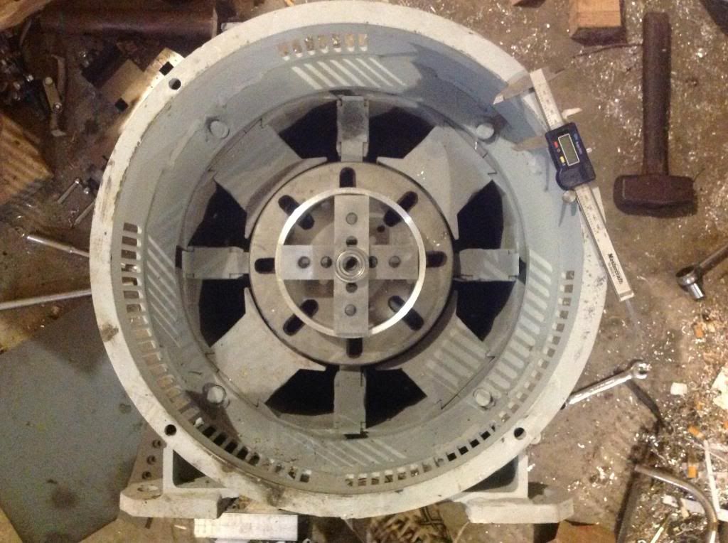
                    Anyway....moving on. I have a plan. If the old man can press out the stators, then life is good and I can modify the fat stators, shorten to make 12" dia., then replace into frame. Then leave 2", then 8" diameter inner stators. I am going to try cutting out the drum from the same metal. I think I can do this operation on my mill, if I can get stators pressed out. I calculated 10.2" (259.08mm)for drum dia, to keep copper volume same on each side of drum.

                    Steel will be heavy, that's why we got the mighty imperial , and the heavy duty shaft. Tesla liked the soft steel laminations. I think we should use steel laminations as well. I'll get 'em thin.
                    Last edited by machinealive; 10-14-2013, 02:20 AM.

                    Comment


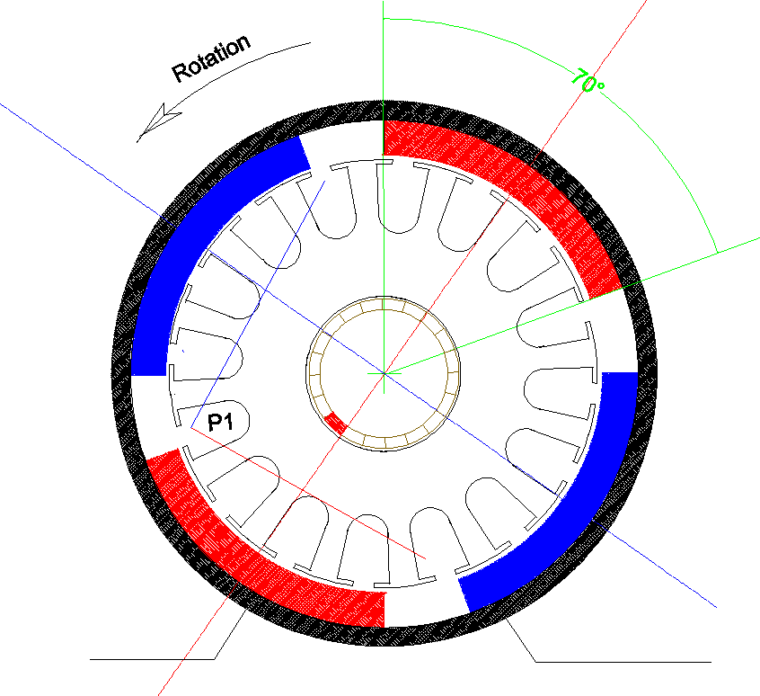
                    • G'day UFO
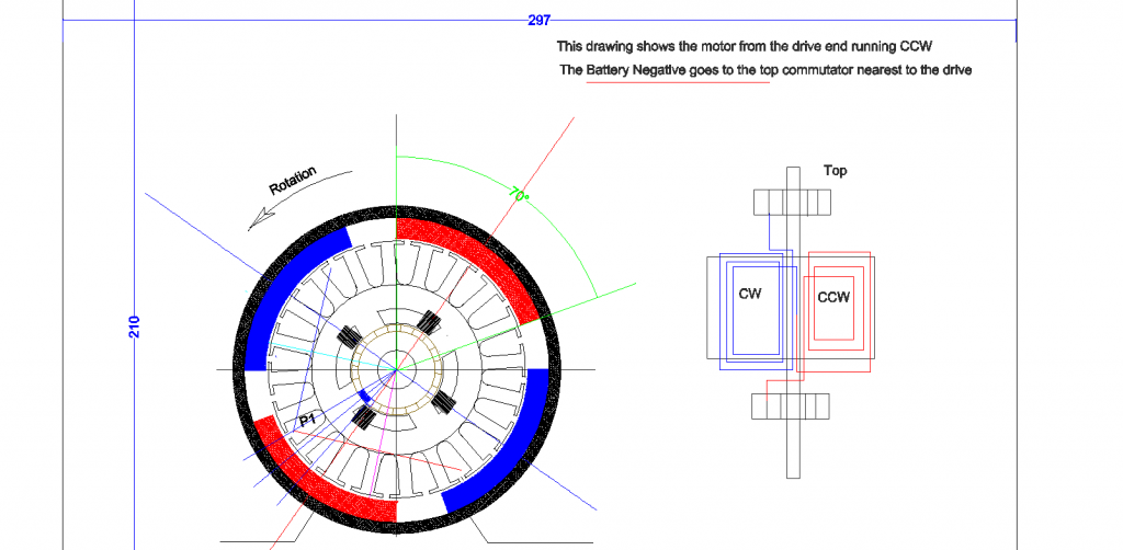
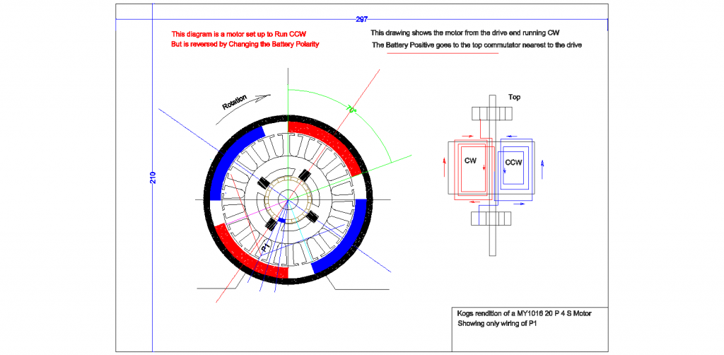
                      I have drawn both my 20Pole 4 Stator motors
                      The first here running CCW


                      Now I have shown the same motor running CW only by changing the Battery Polarity


                      I am Still trying to get my head around the running of these motors before I wind them

                      Please My Friend do I have it right

                      Thanks again
                      and Kindest regards


                      Kogs still thinking Hard

                      Comment


                      • Originally posted by iankoglin View Post
                        G'day UFO
                        I have drawn both my 20Pole 4 Stator motors
                        The first here running CCW


                        Now I have shown the same motor running CW only by changing the Battery Polarity


                        I am Still trying to get my head around the running of these motors before I wind them

                        Please My Friend do I have it right

                        Thanks again
                        and Kindest regards


                        Kogs still thinking Hard

                        Hey Kogs,

                        You have almost all right...except the convention I have shown in my winding tutorial videos

                        THE DRIVE SIDE COMMUTATOR IS ALWAYS THE POSITIVE SIDE

                        But then again , all is relative...and as long as your Right hand rule is very clear...then you could do it your way.

                        Regards

                        Ufopolitics
                        Principles for the Development of a Complete Mind: Study the science of art. Study the art of science. Develop your senses- especially learn how to see. Realize that everything connects to everything else.― Leonardo da Vinci

                        Comment


                        • Originally posted by Ufopolitics View Post
                          Hey Kogs,

                          You have almost all right...except the convention I have shown in my winding tutorial videos

                          THE DRIVE SIDE COMMUTATOR IS ALWAYS THE POSITIVE SIDE

                          But then again , all is relative...and as long as your Right hand rule is very clear...then you could do it your way.

                          Regards

                          Ufopolitics
                          G'day UFO and Thanks for the quick reply
                          I'm still trying to get my head around the winding I want to get it right.
                          Please if my thinking is wrong would you to explain where

                          the convention
                          THE DRIVE SIDE COMMUTATOR IS ALWAYS THE POSITIVE SIDE

                          In my top Pic I show the winding of the CCW motor that has the Negative wire on the Top Commutator That's OK? Right

                          Now I want to go in REVERSE so Using a switch I change the battery connections only and so the motor goes in reverse.
                          So in the bottom pic I show exactly the same Motor this time is it running with the polarity of the battery switched so that it runs in reverse.

                          I did not change anything only the polarity connections
                          I did this to see the connections of the commutator to compared when it is running in reverse and it shows that now the Coil has changed polarity and the coils are now in a different position when the Commutator is just making contact with the brushes.
                          The drive side commutator is still the TOP commutator in the Reversed Mode only the Polarity is different.
                          Will this motor run in Reverse ?

                          I wound 1 NS coil as shown and applied first the Batt positive to the top and noticed the polarity and rotation then
                          I changed the polarity and checked again
                          Batt Neg. on top CW=SP, CCW=NP Motor turns CCW
                          Batt Pos. on top CW=NP, CCW=SP Motor turns CW
                          -------------------------------------------------------------------------
                          I realise that if I want to make a Motor run CW only then I would have to wire it completely in reverse.


                          Kogs gets a headache when he thinks too hard

                          Comment


                          • No Time Now...

                            Originally posted by iankoglin View Post
                            G'day UFO and Thanks for the quick reply
                            I'm still trying to get my head around the winding I want to get it right.
                            Please if my thinking is wrong would you to explain where

                            the convention
                            THE DRIVE SIDE COMMUTATOR IS ALWAYS THE POSITIVE SIDE

                            In my top Pic I show the winding of the CCW motor that has the Negative wire on the Top Commutator That's OK? Right

                            Now I want to go in REVERSE so Using a switch I change the battery connections only and so the motor goes in reverse.
                            So in the bottom pic I show exactly the same Motor this time is it running with the polarity of the battery switched so that it runs in reverse.

                            I did not change anything only the polarity connections
                            I did this to see the connections of the commutator to compared when it is running in reverse and it shows that now the Coil has changed polarity and the coils are now in a different position when the Commutator is just making contact with the brushes.
                            The drive side commutator is still the TOP commutator in the Reversed Mode only the Polarity is different.
                            Will this motor run in Reverse ?

                            I wound 1 NS coil as shown and applied first the Batt positive to the top and noticed the polarity and rotation then
                            I changed the polarity and checked again
                            Batt Neg. on top CW=SP, CCW=NP Motor turns CCW
                            Batt Pos. on top CW=NP, CCW=SP Motor turns CW
                            -------------------------------------------------------------------------
                            I realise that if I want to make a Motor run CW only then I would have to wire it completely in reverse.


                            Kogs gets a headache when he thinks too hard


                            Kogs,

                            I am really sorry, but do not have the time at this moment to go over every detail...

                            All I can tell you is that EVERYTHING is on My First Asymmetric Winding Video::

                            Asymmetrical Winding Part 1 - YouTube

                            Like I wrote in my previous post to you:

                            You've got everything right, meaning Diagrams on Right and Left...However, Your way to feed Negative at the Drive Shaft side Commutator is WRONG...That is all.

                            Also in this "scenario" everything is RELATIVE, meaning you could do it as you like as long as Motor rotates as you want.

                            I chose that CONVENTION as a GUIDE for all to follow and not be asking questions back and forth on different "possibilities"...because there would be many other ways.

                            Go over the First Part of Video and I repeat that SAME Convention very CLEAR.


                            Appreciate your understanding My Friend.

                            You are ready to go for it and WIND it!...just do it and test it...


                            Warm regards


                            Ufopolitics
                            Principles for the Development of a Complete Mind: Study the science of art. Study the art of science. Develop your senses- especially learn how to see. Realize that everything connects to everything else.― Leonardo da Vinci

                            Comment


                            • Originally posted by Ufopolitics View Post
                              Kogs,

                              All I can tell you is that EVERYTHING is on My First Asymmetric Winding Video::

                              Asymmetrical Winding Part 1 - YouTube

                              You've got everything right, meaning Diagrams on Right and Left...However, Your way to feed Negative at the Drive Shaft side Commutator is WRONG...That is all.

                              Also in this "scenario" everything is RELATIVE, meaning you could do it as you like as long as Motor rotates as you want.

                              Appreciate your understanding My Friend.

                              You are ready to go for it and WIND it!...just do it and test it...

                              Warm regards

                              Ufopolitics
                              G'day UFO my very patient Friend
                              I am really sorry I was persistent I must have looked at that video 6 or 8 times I just could not understand why my motor connections were different to yours Finally the light shines I was just winding the CW first and that makes all the difference I will Modify my drawings to correspond to your convention and that way I will be consistent with your teaching.
                              I understand it clearly Now
                              Thanks again my friend


                              Kogs finally stopped so no headaches for at least for a while

                              Comment


                              • Kogs
                                When a person passes over just one small misunderstood point, the rest of his education is clouded. You did good and all is moving on.....
                                Dana
                                "Today's scientist have substituted mathematics for experiments and they wander off through equation after equation and eventually build a structure which has no relation to reality."
                                Nikola Tesla

                                Comment

                                Working...
                                X