First Baldor Commutator completed with connectors
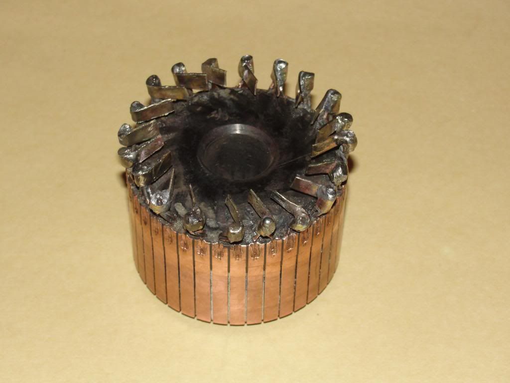
Check this out. 40 segments on commutator for 20-pole motor, each segments had 2 19ga wires coming out of it in that retarded symm winding. I wasn't sure how I would handle redoing the wiring so I left the wires in, cut them off about 1/2" long. Since the manufacturing process stamped the wires into the commutator, I did not feel confident the if I just dremmeled out the wires, that I would be able to make a slot that would hold the wires. My other commutator I did dremmel out the wires, some slots look tight, others not, and they just don't look like the will hold since the manufacturer stamped them. I figure there is one more stamp left in it, which is what I will be doing to it when I mount connectors there on the orig 19ga wire. So here is the commutator with 20 connectors BRAZED onto the wires with my acetylene torch with as low a flame as I could get. I am very relieved that I see no heat damage anywhere!

The challenge with connectors was soldering is verbotten, will melt and splatter when running. I couldn't find the right silver solder, hard stuff, but had some nice brazing rod, lower melting point than gas welding rod. The first few connectors were tough, afraid to heat the commutator too much even with it sitting in a pan of water, and the bazing wouldnt flow into the connector wrapped around the wires even though I had previously brazed the wires into a shaft to hold the connectors. I didn't think I needed flux. Then I came up with the idea to tin the wires with solder and try to get some flux on the top too. Worked good, the solder seemed to act like a flux too, and I figure the solder alloyed into a higher melting point with the brazing, and took less heat as the melting point would be somewhere in between. Connectors look a little long on most, but they should cut down to size easy enough if needed.
I'll be making faster progress on the other commutator since I will be assembling the connectors & wires without them connected to the commutator. I think that will go easier. I plan on using my propane torch there. Then I will be winding soon. (Hope I got the winding direction right) These comms will lend themselves to multiple redesigns methinks. And since I am using a quad-filar design using 30ga, connectors almost seems necessary for that reason too.
Kogs! Congratulations. WOW FANTASTIC MOTOR. Ran so tame, purred!!!! even at 9000 RPM!!!! What a pussy cat! Are you sure that isn't a Radio Shack replication??
I vote for Kogs on the best Imperial replication so far! That is one finished product, ready for manufacture! Nothing left to do but play with the Arduino now
Hey Midaz Sure you want to race with a motor like that?? No big motor growl!
PS I guess I am in a good mood. I have been a little slow on my build for a lot of reasons, but for some good ones too, I have my first granddaughter now!
Check this out. 40 segments on commutator for 20-pole motor, each segments had 2 19ga wires coming out of it in that retarded symm winding. I wasn't sure how I would handle redoing the wiring so I left the wires in, cut them off about 1/2" long. Since the manufacturing process stamped the wires into the commutator, I did not feel confident the if I just dremmeled out the wires, that I would be able to make a slot that would hold the wires. My other commutator I did dremmel out the wires, some slots look tight, others not, and they just don't look like the will hold since the manufacturer stamped them. I figure there is one more stamp left in it, which is what I will be doing to it when I mount connectors there on the orig 19ga wire. So here is the commutator with 20 connectors BRAZED onto the wires with my acetylene torch with as low a flame as I could get. I am very relieved that I see no heat damage anywhere!

The challenge with connectors was soldering is verbotten, will melt and splatter when running. I couldn't find the right silver solder, hard stuff, but had some nice brazing rod, lower melting point than gas welding rod. The first few connectors were tough, afraid to heat the commutator too much even with it sitting in a pan of water, and the bazing wouldnt flow into the connector wrapped around the wires even though I had previously brazed the wires into a shaft to hold the connectors. I didn't think I needed flux. Then I came up with the idea to tin the wires with solder and try to get some flux on the top too. Worked good, the solder seemed to act like a flux too, and I figure the solder alloyed into a higher melting point with the brazing, and took less heat as the melting point would be somewhere in between. Connectors look a little long on most, but they should cut down to size easy enough if needed.
I'll be making faster progress on the other commutator since I will be assembling the connectors & wires without them connected to the commutator. I think that will go easier. I plan on using my propane torch there. Then I will be winding soon.
 (Hope I got the winding direction right) These comms will lend themselves to multiple redesigns methinks. And since I am using a quad-filar design using 30ga, connectors almost seems necessary for that reason too.
Kogs! Congratulations. WOW FANTASTIC MOTOR. Ran so tame, purred!!!! even at 9000 RPM!!!! What a pussy cat! Are you sure that isn't a Radio Shack replication??

I vote for Kogs on the best Imperial replication so far! That is one finished product, ready for manufacture! Nothing left to do but play with the Arduino now

Hey Midaz Sure you want to race with a motor like that?? No big motor growl!

PS I guess I am in a good mood. I have been a little slow on my build for a lot of reasons, but for some good ones too, I have my first granddaughter now!


 . So, UFO, I guess we must have cooked our motors right off the bat last time,
 ...I feel it better emphasizes the question...
 The woman's game, was a heart stopper.


Comment