Announcement

Collapse
No announcement yet.

My Asymmetric Electrodynamic Machines

Collapse
X
 
  • Filter
  • Time
  • Show
Clear All
new posts

  • Experimenting

    Yes UFO I did know I wasn't supposed to run it on that much voltage. I just bumped it with what I had in front of me to make sure it was going to spin. I am just experimenting. I have a few of these motors and I plan on having a few different interchangable rotors so I can see for myself the difference. With this gage I don't think I could get another 2 wraps per coil. It may just be a failure attempt but that's ok. It is all part of learning the perameters.

    Comment


    • Wonderful Kogs!

      Originally posted by iankoglin View Post
      G'day UFO and Team
      I made another attempt at putting the out put back into the battery
      the car batteries are ones I am in the process of rejuvenating when I got the batteries they would not hold a charge at the moment I would say they are half way to being completely rejuvenated
      The Motor has 2 sets of brushes the Motor brushes are in parallel and the Generator brushes are also in parallel.
      You notice that the battery is connected to top of both comms and the output is directly taken from the 2 bottom coms to the Cap bank of 8 12000uf 63v caps in parallel with a Diode on each Negative into and out of the Cap Bank

      I have the video on YouTube here
      MY 250w 24v output into cap bank back into24 car battery - YouTube

      The voltage of the batteries started @ 24.9v rested from charging and finished up24.10v @ 3:00pm and @ 3.25 hours after I finished the video 6:15pm the batteries were rested @25.07v and still after another 1:40 later @7:55 the volts finished @25.12

      When I started the video I only had the pot about between 1/2 and 3/4 on
      You can notice how the Amps went up when I put the Pot full on at 2:42
      then the Amps quickly jumped and settled down
      The temperature I am not really satisfied as it went up progressively until it reached 61.9C (144f) I do not know how the batteries will go in Nessie as I was not going to ventilate them But I see now I will have to fan them to keep them cool
      I will do a different test after I Re Charge the Batteries and post again

      Kindest regards to all

      Kogs still at work

      Nice Testing Kogs!!

      It is better to have the Output Gates in Parallel when trying to charge batteries...since Amps would be higher than in series, where Voltage increases.
      Batteries need Higher Amperage rates to be charged faster...but of course, a typical charger would regulate this High Amps discharge process to occur NOT continuously, as it may burst batteries. Same way it is done with large LiPo's Banks charging spec's.

      One thing that I will love for you to do...and I know it is hard, cause you already have varnish and balanced those motors...is to go for the ALL NORTH Configuration Kogs...if you could just do another MY1000 Motor like that...preferably a 20 poles...then run the tests and watch the big time difference my friend!


      Kind regards


      Ufopolitics
      Principles for the Development of a Complete Mind: Study the science of art. Study the art of science. Develop your senses- especially learn how to see. Realize that everything connects to everything else.― Leonardo da Vinci

      Comment


      • Supercaps Testing soon...

        Originally posted by Zardox View Post
        Yes UFO I did know I wasn't supposed to run it on that much voltage. I just bumped it with what I had in front of me to make sure it was going to spin. I am just experimenting. I have a few of these motors and I plan on having a few different interchangable rotors so I can see for myself the difference. With this gage I don't think I could get another 2 wraps per coil. It may just be a failure attempt but that's ok. It is all part of learning the perameters.
        Hello Zardox,

        When I finished that little motor with 8 turns...I noticed I still have quite some room to do couple more turns...and as a matter of fact...I did originally on the first Pair...Twelve turns...not saying I did the whole thing though, just P1, but it was too much resistance, then I started taking off pieces/turns by pieces/turns....till I got the desired value.

        I ordered some Supercaps...I wanna do a running test with supercaps on each gate (Input/Output)...and see where we get...


        Regards


        Ufopolitics
        Principles for the Development of a Complete Mind: Study the science of art. Study the art of science. Develop your senses- especially learn how to see. Realize that everything connects to everything else.― Leonardo da Vinci

        Comment


        • I ordered some Supercaps...I wanna do a running test with supercaps on each gate (Input/Output)...and see where we get...
          Now, that's what I'm talking about!


          Keep it Clean and Green
          Midaz

          Comment


          • Comment on video and test data on GM window motor

            Hi Ufo,
            Maybe the motor is breaking in and running easier and more efficiently, maybe even since it is warming up and expanding. That might explain only a temporary creep in rpms up, amps down and creep up on volts, though? But the proof would be if the batteries continue run 2-3-4 times ? longer than a conventional motor even if it performs just somewhere close in the rpm/amp range. So whats the battery behavior on a conventional motor, does it never creep up? A new conventional motor would also have a break-in cycle, wouldn't it? First time I noticed the capacitor in the circuitry, gotta study that to see where you are putting it.

            Took some more data on my dual stator. Motor turns better on direction vs. the other, one brush set runs better than the other. Now my motor is 26ga. also, its the group unipolar winding for the 10-pole. I had 11 turns per sub-group coil, 4 subgroups per group at 32' per coil. I calculated this using the Alcatel Magnet Wire guide by wire diameter and resistance, figuring 1.1 ohms per GROUP. The double rotor came in perfectly filled up. I used my best radio shack mulitmeter, seemed to agree with the Alcatel Magnet wire guide completely. How in the world did you get a coil coming in around one ohm on that little motor using 26ga?

            Well anyway, I loosened my brushes up a bit and put some washers to reposition brushes housings getting some more clearances, now getting 3400 rpm on 12v on the best brush set, about 9v on the other brush set measuring output voltage there. When I hooked up a 12v incandescent light to the 9v generator output, it took about .17A and lighted well, and the motor slowed and took an extra .1-.2A.

            When the motor was free running on one brush set, it took 1.45A

            Hooked up the second brush set as a motor. To do this I had to put the +8v gen. side to the +12v terminal of the battery, got 4000 rpm. I am confused by this, its as if the battery is fighting the "generator" output. Had ammeters on each brush set, and the amperage distributed across both, but not completely evenly, probably due to some extra resistance built into the slow brush set, .6A on it and .85A on the fast one. So how about that, more RPMs at same amps!

            Ran it for over a half hour, got up to about 108 on the body, 110 by one brush set, after loading it for a while down to about 2800 rpm and over 2A. So it seems to be able to work...

            Hey looks like my window motor runs like your sullivan unipolar pair design, rpm and amp draw very similar.

            Getting real intriguing how it might run on a pulser or how a straight Pair coil design might work instead. have to get the wires under control before I can make a nice video. Making another double rotor on the table, Pair design, got the parts.
            Last edited by sampojo; 05-16-2014, 03:59 AM.
            Up, Up and Away

            Comment


            • New rotor:GM unipolar dual stator vs QP10 quad stator

              Hi Ufo

              I am thinking about making a new rotor. I like my QP10 quad motor for power generation capability, since the motor body is wall-to-wall covered with magnets in a quad stator layout. It has a construction weakness in that I used solder on the external wiring connection, that I believe I can replace with crimps. At 26ga it ran a little hot at 130defF coming out along the endplates., .6-.7ohm coil pair wQP10 winding pattern.

              I like my doublerotor dual stator alot since it ran cooler, twice the wire then of course and ohms prbly at about 1.1 per group, apparently less powerful too!. I don't like the shorter magnets now either.

              You asked me a question back on pg 219 P6566, here is the discussion:


              Originally posted by sampojo to Ufo P6566 View Post
              Sam: My Quad stator pentagon winding motor did 7500 rpm on one brush set if I remember right, drew 2.5A, 8600 with 2 brushes. I think I had .7 ohms per brush set though, got up to 130 dF the day I blew a brush set, used solder. so it needs reworked.

              Ufo: One question...are this two motors (Quad and G-10) same spec's as rotor wise?...If so, could you run the G-10 Rotor inside the Quad Stators/Brushes housing?

              Sam: no can do. The dual stator was a double rotor - 4", the quad was 2". I hoped to make up for it being only a dual stator by making it longer, and of course, putting the two bodies together was easier, since you could duplicate the original motor's brush and endplate assembly to the commutator placement, no thinking and simple measurements to dupe.


              yes absolutely no adjusting. I think a big drawback now to these motors is the magnet's are shorter in width as I posted earlier on this page. The motors are made to be narrow to fit in a door Bad for doing real work as I have some plans on seeing how much energy it can make. But I am happy with the ohms per group and heating seems very under control and will look at 24v. I think I used 26ga on the quad and it had .6-.7ohms per coil, and the brush assemblies are just not heat tolerant, failed a brush set fast (haven't disassembled yet to find out exactly). Pretty sure its best to pursue your unipolar windings though instead. I would rather rewind it that way, before I do anything serious with it. I might try to repair it just to get good comparisons to the unipolar. I would almost say that I should go up a gauge to 27ga on it also, since it ran so hot. But maybe need to get the pulsers working to see how they help.
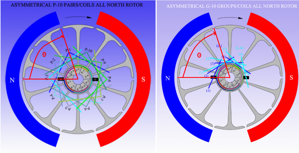
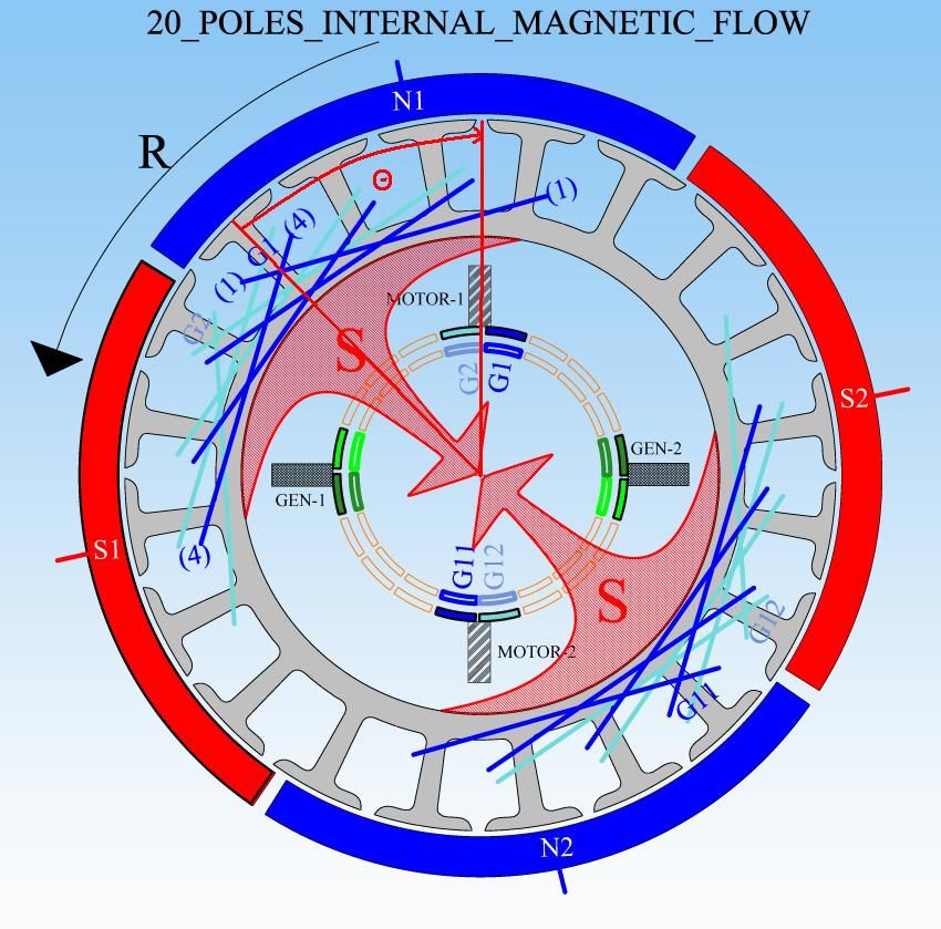
              I have enough rotors and commutators to make a new motor core methinks pretty quickly. Many serious home front priorities now however. Yes could there be a possibility that your original RS unipolar pairs is a better design? A new rotor winding of that type would be the ticket to answer that!
              When you asked if I could put the G10 rotor in the body of my QP10 you seemed to imply that the dual stator group winding might work in the Qaud stator design. Maybe not huh? But what about the P10 unipolar which I would like to investigate. Sure I can do the P10 double rotor for a dual stator and we know it should work well, but I like the wall-to-wall magnets in the QP10 motor body. I guess 26ga is still optimum there, since I should be able to recoup heating as a problem by using pulsers, which I am starting a more agressive assembly campaign on those. But I think you have alluded to differences in quad stator designs. And overall I want to test the Pairs unipolar design. I think the 44000 rpms you got on the RS 5-poles unipolar pair design is the effect I want to work with most.

              Question: Do I need a redesign of the P10 unipolar dual stator design for a Quad Stator motor?

              Looks like answer is no if I compare the timing angles, group vs pair unipolar looks constant. But the 20 Pole Quad stator Bosch diagram timing angle looks a little larger at 4 1/2 poles vs. a translated 4 poles (Theta in the diagrams)
              10-pole Group vs Pair design have same theta


              Looking at coil G1 firing here, 20 pole quad stator has similar Theta, maybe a little smaller by 1 1/2 pole arc?


              So It looks like rotors would not be interchangeable in unipolar motors between quad and dual stator designs to me since the theta's are very different, and one leading and one lagging the motor brush.

              So a Pair unipolar 10-pole design for a quad stator would use the same timing angle used by the Quad stator 20-Pole apparently, and the sub-coils would subtend 2-poles?

              Thanks, Ufo
              Last edited by sampojo; 05-19-2014, 04:14 AM.
              Up, Up and Away

              Comment


              • wiring diagrm reqeust p6481

                Originally posted by Ufopolitics post 6481 View Post
                Hello My Friends,

                Well, here is the Video about the P-10 All North Tests...

                https://www.youtube.com/watch?v=-DUK...ature=youtu.be

                [IMG][/IMG]

                And like I said on Video...This Motor Configuration (with this small Power Source) will not show a huge Increase on RPM's acceleration like the small RS Five Pole did, #1 because of mass, and second Coils size and Capacitance...HOWEVER...IT DOES INCREASE UNDER LOAD!...Never decreasing, but JUST for a few seconds till it stabilizes back then start the "ASCENSION TO HEAVENS" Curve...

                Now, the second Test I did on Video is just to clear doubts...mainly at my You Tube Channel...some comments I will quote below...which I find "Logical and Making Sense" though...Big Claims require Big Time Proof...Big Time Testing...and I agree 100%...plus many have the right to doubt them.


                Sorry Guy...PSU either did not wanted-this time only- to put that xtra power now??!!

                Anyways, this is fun...

                The Second Test...I clearly show that Power Source can NOT put out with both components at once, Bulb and Motor...no matter how...I connected them...tried in Parallel...Motor Collapses...PSU Relay of overload clicks in...PLUS in series does only 2600 RPM's plus a dimmer Bulb..

                Now...what happened?...where is that Energy coming from?...that ONLY with Motor feeding Bulb through its Generation Gates...it can do OVER 5000 RPM's PLUS keeping Bulb brightly ON??!!

                And we are not lighting here CFL's...NOR LED'S...


                Enjoy it Guys


                Au Revoir


                Ufopolitics
                Ufo I don't understand where the "rear junction" hook up goes and which "two ????? terminals" you are using. I need to see how the G10 does vs the P10 here. where do you hook the bulb up when it looks like you are using gen terminals on the "rear junction".
                Up, Up and Away

                Comment


                • Supercap Test Part 1

                  https://www.youtube.com/watch?v=-Afl...0YnD2b5zasXXng

                  Hello to All,

                  Above is the First Test I conduct with Supercapacitors...here is just one of them, replacing the typical electrolytic I used on previous video...so We can see how much the Supercap enhances the Effect, on Self Acceleration and Regeneration of Voltage In (V In) at Right hand side Meter.

                  [IMG][/IMG]

                  This Test clearly shows that we have a Progressive Regenerative Effect that develops much faster than with typical Electrolytic Caps...more layers...more density of currents.

                  Caps that I used here are MAXWELL 310 Farads and 2.7 Volts.

                  I am making Three Videos...this is first...on second I will NOT be using this approach on Cap connection, but a COMPLETELY NEW way to connect a feed to this Machines...then at the Final Video I will be showing the "Fusing" of both type of connections and the "Advantages" I will be very glad to demonstrate.

                  On the video, sorry about some background sound tracks going a bit crazy on volume levels...but you will see the whole effect clearly.


                  Thanks and Regards


                  Ufopolitics
                  Principles for the Development of a Complete Mind: Study the science of art. Study the art of science. Develop your senses- especially learn how to see. Realize that everything connects to everything else.― Leonardo da Vinci

                  Comment


                  • Originally posted by sampojo View Post
                    Ufo I don't understand where the "rear junction" hook up goes and which "two ????? terminals" you are using. I need to see how the G10 does vs the P10 here. where do you hook the bulb up when it looks like you are using gen terminals on the "rear junction".
                    [IMG][/IMG]
                    Principles for the Development of a Complete Mind: Study the science of art. Study the art of science. Develop your senses- especially learn how to see. Realize that everything connects to everything else.― Leonardo da Vinci

                    Comment


                    • Analyzing Diagram...

                      Hello Again,

                      On this separate post I will go over about what's going on inside Machine...and why I believe is doing this "Effect":


                      [IMG][/IMG]

                      For all of you familiar with My Machines and specifically this type of all North config...

                      L1 receives a feed from battery, then once magnetized it rotates and becomes L2, here it creates a "momentary" LC Circuit with Supercap, where Cap receives a dumped charge as also L2 magnetizes in resonance for the short time of closed loop, this creates a strong field and acceleration starts becoming more robust...after disconnection it goes back to L1 POSITION, where excess charges are dumped back to Battery...and so on and on...NOW, realize we have here FIVE L#...so it is L1, L2, L3, L4 and L5 swapping places constantly during rotation.

                      Since ALL COILS are North or same winding directions...they generate same magnetic fields (no matter if North or South)...then the Spatial "Ring" around Rotor is ALL BLUE...or All North...the same direction Energy is "lingering" in its environment...so, "sucking" from this constant UNIPOLAR FIELD is not such a big stress...or such big job...like when Spatial Field is completely canceling to Zero Value at every spin in North-South Configurations.


                      Hope you see all this clear...because what's coming next is not that simple to "digest"...and has absolutely nothing to do with above...however, they will "blend" perfectly in beautiful harmony in the end...


                      Regards to All


                      Ufopolitics
                      Last edited by Ufopolitics; 05-20-2014, 11:19 PM.
                      Principles for the Development of a Complete Mind: Study the science of art. Study the art of science. Develop your senses- especially learn how to see. Realize that everything connects to everything else.― Leonardo da Vinci

                      Comment


                      • YES! most impressive

                        Ufo very nice demo. When you slip the cap in simply charge it up to battery voltage first, connect in parallel with battery, let it run a little bit, get the voltage up some more, than viola, disconnect battery, smooth, easy peasy.
                        Up, Up and Away

                        Comment


                        • Originally posted by sampojo View Post
                          Ufo very nice demo.
                          Thanks Sam,

                          When you slip the cap in simply charge it up to battery voltage first, connect in parallel with battery, let it run a little bit, get the voltage up some more, than viola, disconnect battery, smooth, easy peasy.
                          See Sam, that's what I do NOT want to do now (or pre-charge Supercap by a different source/charger)

                          What I want to demonstrate (and I will do just that in my next video...) is to show that our Machines, no matter how small the set up is...Machine is ABLE TO CHARGE Supercap ABOVE Starting Battery levels (Generator Capabilities)....trust me, I have done it by now...

                          Problem with Supercaps is that when they are Zero Charge...or Negative Values...they will become a SHORT CIRCUIT to our Machines...so a very small precharge must be done (200 to 300 millivolts) in order to add some resistance.

                          I know you will love what is coming next couple of videos...


                          Take care


                          Ufopolitics
                          Last edited by Ufopolitics; 05-20-2014, 11:32 PM.
                          Principles for the Development of a Complete Mind: Study the science of art. Study the art of science. Develop your senses- especially learn how to see. Realize that everything connects to everything else.― Leonardo da Vinci

                          Comment


                          • Great Stuff UFO, and very well explained, it would be interesting to see what happens if you put a gentle mechanical load on motor shaft.

                            Warm Regards Cornboy.

                            Comment


                            • Nice demo

                              Nice demo UFO!
                              Would I be right in assuming that when the super cap was charged to a voltage high enough to run the machine the battery could be disconnected and a second super cap could be put in its place?
                              I would like to mention my experiment with using the 22 gage wire. It is actually 2 of the goldmine motors set end to end with a gap between the two rotors but wound as one. At this point I need to modify the end plates so I can adjust the timing. As it is it is set at the factory timing. As it is it will not run on the lower voltage as you are showing or maybe my battery just won't put out enough amperage. It does however run just fine on my 10 volt alum converted motorcycle battery. There is no arcing in the commutators and it does not get hot. If the timing was adjusted I think it could do much better as I am only seeing just under about 8 volts on the output. I did hook the shaft directly to a 18 volt trimmer motor with not so good bearings and got 17 volts out of that as well. I don't have much time to work on this at this time of the year so my apologies for not getting things done in more of a timely fashion. I only mention my work in hopes that my results might be of help and do not want to detract from your work in any way.

                              Comment


                              • Dual Supercaps Crossfiring Machine Coils...

                                Hello to All,


                                [IMG][/IMG]

                                Above I am showing a completely new and different way to feed my Machines...yes, we could also feed them like that with side battery Banks as well as caps...but on the following video you will observe how well the Super-caps get charged with this little motor...

                                SUPER CAPS CROSSFIRE (PART 2)

                                On the video I explain clearly on my "hand sketch" how this works...the final part is that Caps get charged by "half" charge from battery/L1 and the other half enters through our collapsing coils (L2) reversed currents...

                                We only test here C1 & C2 as Side Supercap Banks...No C3 shown here, like on First Video (Buffer Cap)...This Buffer Cap keeps bouncing charges back and forth between this Two Crossfire ends...and when I disconnect batteries...it starts "filling up" from both ends...they start a "Communication Network" between Parallel and Series Resonance...and we will put all this in schematics so we could discuss the best way to keep harmonics through electronics control, in a more accurate fashion...


                                I wanted to show here, mainly, the Generating Capacity of such small Five Pole All North Asymmetric Machine...to the point Motor "feeds back" itself reaching over 13,000 RPM's on a power it generated, using only Milli volts.


                                Once I complete this 3 videos, I will move on to "Bigger Toys"...I miss them...besides this little machine is limited by the number of poles/coils...and that reflects on the speed to regenerate and acceleration properties...

                                The "Effect" I am trying to achieve now...is to observe the same increase on Supercaps as We have seen in Battery before...while acceleration increases also...but it is not a simple deal guys...it occurs at specific speeds...and specific voltage levels from THREE POINTS at Caps...or decay will prevail...so, lots of development...and lot of frustrated testing as well.


                                Hope You enjoy this part...


                                Regards to All


                                Ufopolitics
                                Last edited by Ufopolitics; 05-23-2014, 12:18 AM.
                                Principles for the Development of a Complete Mind: Study the science of art. Study the art of science. Develop your senses- especially learn how to see. Realize that everything connects to everything else.― Leonardo da Vinci

                                Comment

                                Working...
                                X