Announcement

Collapse
No announcement yet.

My Asymmetric Electrodynamic Machines

Collapse
X
 
  • Filter
  • Time
  • Show
Clear All
new posts

  • Originally posted by prochiro View Post
    Sampojo

    Going back to fifty to seventy pages ago I saw that UFO asked you to try a Litz wire version. I see where you asked a lot of questions and mentioned the multiple wire at several other points. What I do not see is any reference to a finished motor using litz wire or data about it. For others who are interested, I am showing my data about litz equivalent AWG.

    Equivalent ___Number ____AWG of wire____LBS. per ______Resistance____
    AWG________of wires___________________1000ft._______OHM/1000ft.__

    26__________ 3 _________30 ___________.95 ___________35.98
    24__________ 5__________30__________1.58____________21.59
    22__________ 7__________30__________2.21____________15.42
    20__________ 11_________30__________3.47____________9.81
    18__________ 17_________30__________5.52____________6.35
    16__________ 26_________30__________8.38____________4.15


    I have many more types of formulas and patterns but these are for 1Hz to 10KHz and are the best for our winding , all with Construction type 1 which is just wind them all together as one wire.

    On average with say 12 volts into a coil, you can expect from 1/4 to 1/3 more of everything including BEMF.

    I have ordered a spool of 30 AWG wire and will be winding a goldmine motor with all north with 3/30 litz for comparison in the near future. I will be twisting at about 6 turns per foot. If others have an extra RS motor and some 30 AWG, you are invited to do the same, but remember to compare to another all north motor of same size.
    Here is more data
    http://litzwire.com/nepdfs/Round_Litz_Catalog.pdf

    Dana
    Hello Dana, Thanks for the link, it's an eye opener isn't it. If anyone here hasn't used multiple strands you might be surprised how nice it is to wind. If you look at the same gage across the charts (say #18) you can use 10 strands to 1100 depending on the size you're litzing with? Man I never thought about using such fine wire. Do you ever question whether or not you miss any ends when you solder? I use wire that has a coating that you can solder through, it sort of just melts out of the way and that helps. Using a little paste on the end to help the wire tin has worked for me also. If you miss to many strands you're resistance measurement will be off right?
    Out of curiosity, has anyone here ever used litzed wire with nearly 1000 strands?
    John

    Comment


    • John

      I have not used past seven wires but have torn down a Delco Rotory Transformer that had such fine wire that I could not even measure it. It looked like many small hairs but upon rubbing the ends, that was even smaller wires in that.
      Dana
      "Today's scientist have substituted mathematics for experiments and they wander off through equation after equation and eventually build a structure which has no relation to reality."
      Nikola Tesla

      Comment


      • Originally posted by prochiro View Post
        John

        I have not used past seven wires but have torn down a Delco Rotory Transformer that had such fine wire that I could not even measure it. It looked like many small hairs but upon rubbing the ends, that was even smaller wires in that.
        Dana
        Dana, I have a few of those transformers covered with spider webs somewhere, maybe I'll have a look. I've had trouble breaking wires while winding with anything #30 or smaller. Somehow home litzing might get some wires shorter than others or something. Good luck with your Goldmine motors. Has anyone used this particular one, or know anything about it like how many poles? It also looks like it might have real bearings in it.
        Electronic Goldmine - Massive 12VDC Motor
        John
        Attached Files

        Comment


        • Hi,

          Sorry Ufo for bringing to your thread this off-topic post, but I know that into this thread has sometimes appeared the patent 3,913,004 by Robert Alexander about his motor - generator. Also I know that in this thread there is very knownledgeable people and ,maybe, someone could be interested in the detail I will show next.

          After watching carefully Robert Alexander US patent 3,913,004 drawing I have discovered that the correct polarity in the Alexander device is with like poles facing each other ( N-N !!!) Alexander drew it so that everyone would think that was N-S, but if you interpret correctly his drawing you will note the correct polarity of the magnets. Maybe Alexander was trying to hide this feature.

          I attach a corrected sketch below.
          Attached Files
          Last edited by hanon1492; 09-06-2014, 03:14 PM.
          https://figueragenerator.wordpress.com/

          Comment


          • Wrong interpretation Hanon...

            Originally posted by hanon1492 View Post
            Hi,

            Sorry Ufo for bringing to your thread this off-topic post, but I know that into this thread has sometimes appeared the patent 3,913,004 by Robert Alexander about his motor - generator. Also I know that in this thread there is very knownledgeable people and ,maybe, someone could be interested in the detail I will show next.

            After watching carefully Robert Alexander US patent 3,913,004 drawing I have discovered that the correct polarity in the Alexander device is with like poles facing each other ( N-N !!!) Alexander drew it so that everyone would think that was N-S, but if you interpret correctly his drawing you will note the correct polarity of the magnets. Maybe Alexander was trying to hide this feature.

            I attach a corrected sketch below.
            Hanon,

            It is ok to post here, however, look again at original Patent drawing...if you notice about TWO details.

            1- First, note his Generator winding, which is done in a "Series Continuous Turns".
            2-Also note the Generator Output is clearly shown as an AC Sine wave.

            Now, if He would have same polarity in Stators, as you are referring to in the colored poles second diagram you did...whether N-N or S-S facing rotor windings...first than all, according to way of winding plus same polarity at stators...it would output an always positive sine wave friend....I believe you know that right?...since we discuss it before in your threads, and I recall you posting about this...

            On the Motor end...it does not make sense either, to have same polarity Stators...I have done it with the All North ROTOR type (it could only be achieved with this type)...but does not work as well as N-S Arrangement in the Stators...which I also have posted here.

            Anyways, hope you could see what I mean...

            Regards


            Ufopolitics
            Principles for the Development of a Complete Mind: Study the science of art. Study the art of science. Develop your senses- especially learn how to see. Realize that everything connects to everything else.― Leonardo da Vinci

            Comment


            • Making a Small AC generator

              Ufo, Some questions on this.


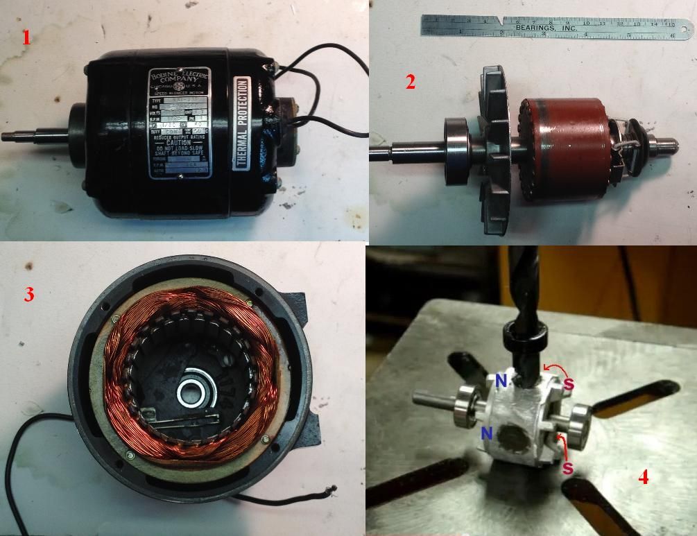
              In pic 2, notice my 1-5/8 long rotor block. I could only find arc magnets of neodymium at 1" long. And they lied said they were 1/4" thick, they werent, so my gap between my rotor block and the coils is at about 1/16", a little larger than before. Also the steel frame of the coils is exactly the same size as the old rotor block. I don't feel like even trying to cut the neo's down to size and just want to make a new rotor block 2" long, extending beyond the coils steel frame about 1/4" each side. Overall the coils are 2.5" long.

              Are any of these mismatches showstoppers?

              Notice the starting mechanism on the end of the rotor. When it reaches a certain rpm it trips into the normal run range by hitting a switch inside the motor. you can see the switch in picture 3

              Is this needed for the generator option?

              I don't suppose but then I should set the switch to the normal run mode, otherwise it will be stuck in a low voltage mode of operation perhaps?

              TIA
              Up, Up and Away

              Comment


              • Ac Induction Motor To Generator...

                Originally posted by sampojo View Post
                Ufo, Some questions on this.


                In pic 2, notice my 1-5/8 long rotor block. I could only find arc magnets of neodymium at 1" long. And they lied said they were 1/4" thick, they werent, so my gap between my rotor block and the coils is at about 1/16", a little larger than before. Also the steel frame of the coils is exactly the same size as the old rotor block. I don't feel like even trying to cut the neo's down to size and just want to make a new rotor block 2" long, extending beyond the coils steel frame about 1/4" each side. Overall the coils are 2.5" long.

                Are any of these mismatches showstoppers?

                Notice the starting mechanism on the end of the rotor. When it reaches a certain rpm it trips into the normal run range by hitting a switch inside the motor. you can see the switch in picture 3

                Is this needed for the generator option?

                I don't suppose but then I should set the switch to the normal run mode, otherwise it will be stuck in a low voltage mode of operation perhaps?

                TIA
                Sam,

                I have been trying to tell you friend...this kind of 'conversion' will never work as well as a real AC Generator, unless you change the whole thing, meaning, mainly the stator windings...I don't know if going through all this trouble will be worth it, just because you won't get out what you may be expecting.

                Say you find the right magnets, or cut them to size, use more down vertically and add them stacked to reach the 2.5 inches...say you finish your rotor...You will STILL, NOT get out the same way as you will obtain of a real AC Winding Generator...they ARE NOT THE SAME, and I have made (specially for you) the Diagram below, trying for you to see what I mean:

                [IMG][/IMG]

                Take a look again at your windings at stator...they should look like in FIG 1...meaning they are piled together comprehending "X" number of poles...then they jump to another 'Layer' to wind same thing.

                The way a dedicated winding for an AC Generator for the Induced Coils works...is like shown on FIG 2...Notice they have each coil winding jump every SINGLE POLE...and I only drew a single line...but they are several strands of wire on each slot...now this guarantees that EVERY SINGLE SLOT is gonna have several VERTICAL WIRES that would be inducing currents at every single degree of rotor movement...so you get a ROBUST AC OUTPUT.

                Understand now my friend?

                I mean, I do not want to disappoint you about your project...but at the same token, I feel it would be worst that after all that trouble...you do NOT have out whatever Energy Rate you were expecting.

                Even if you take apart that winding...and try to rewind it according to FIG 2...still, all the resistance, number of turns, wire gauge and area of 'induction' (number of poles) MUST BE CALCULATED accordingly, in order to output the required AC 120 V and say 15 Amps at a specific speed (RPM's), say 'conventional' 3600.

                That switch, like you said...is not needed for AC Generator, HOWEVER, that switch turns on and off the Two Speeds of Two Different Windings-Layers on Stator...so make sure you choose the lowest resistance one, in order to get a more robust AC (Amps wise)...

                The Guy on video you linked previously shows an output of like 50 Volts, after all that trouble...but HOW MANY AMPS?...I did not see he measured that parameter.

                Final point am trying to get at...is that I do not want you to expect to make that small motor output like even the same size dedicated AC Generator. And am not saying you will not get anything at all...you will, and to 'prove a point' is fine...but for real applications it won't work.


                Regards my Friend!


                Ufopolitics
                Principles for the Development of a Complete Mind: Study the science of art. Study the art of science. Develop your senses- especially learn how to see. Realize that everything connects to everything else.― Leonardo da Vinci

                Comment


                • Originally posted by hanon1492 View Post
                  Hi,

                  Sorry Ufo for bringing to your thread this off-topic post, but I know that into this thread has sometimes appeared the patent 3,913,004 by Robert Alexander about his motor - generator. Also I know that in this thread there is very knownledgeable people and ,maybe, someone could be interested in the detail I will show next.

                  After watching carefully Robert Alexander US patent 3,913,004 drawing I have discovered that the correct polarity in the Alexander device is with like poles facing each other ( N-N !!!) Alexander drew it so that everyone would think that was N-S, but if you interpret correctly his drawing you will note the correct polarity of the magnets. Maybe Alexander was trying to hide this feature.

                  I attach a corrected sketch below.
                  You can see it more clear in Figure 2 of Alexander patent. The right stator pole orientation is North- North. I can not explain why, but this is a real fact. Figure 1 is the one that everyone knows and that figure 1 is drawn to mislead us.


                  Regards
                  Attached Files
                  https://figueragenerator.wordpress.com/

                  Comment


                  • Alexander

                    Yes, this is an off topic post. But as you are persistent, I will respond. I see no evidence that any of the drawings show other than NN and SS. I think that what you are referencing to is the letter S on the face of the magnet on the right on fig. 1 or the large S at the top in fig. 2. In any case, the two figures show NN and SS. You are confusing different types of labels.

                    In any case, this patent is full of vague and incorrect information so far off that I would not trust any of it. The only way to get a handle on this is to really study dynamo's and DC to AC transformers well. After that one may make more accurately a guess at just what was the real deal.

                    As UFO said, the motor would not work that way. There is something vary important missing in this patent and it is not just the magnet orientation. Dynamo's are not wired at all like as shown on patent. I think that he left out the whole wire winding truth as his protection as do many others. This leads to only the patent owner knowing the truth and the rest of civilization looses when he is gone. It really does not matter if the poles are messed up as so much is missing in other areas that you will have to reinvent the whole thing.


                    Robert Alexander/Free Energy/AG

                    I hope this ends this topic.
                    Dana
                    Last edited by prochiro; 09-08-2014, 02:06 PM. Reason: add contact
                    "Today's scientist have substituted mathematics for experiments and they wander off through equation after equation and eventually build a structure which has no relation to reality."
                    Nikola Tesla

                    Comment


                    • Just hello

                      Hey Ufopolitics,
                      This being September I guess many are working on the Imperial motor and the new all north winding. Wow, I hope nothing but success for everybody's work.
                      Looking forward to your progress and future experiments.

                      I may rewind the old generator with thinner size wire as it yet pulling many amps with very little generator side output AC or DC.

                      Or.
                      The field coils are only six volt coils and I need to replace them with 12 volt ones.
                      I saw the 38A A1 24 volt generator for the army jeep. The shoes and coils in the case seem to be same size as this delco remy I'm using. Will ask owner the sizes.

                      Best to All on your builds,
                      wantomake

                      Comment


                      • Hi guys!

                        Here is the first ever 100% Electric F1 race, Formula E 2014 Beijing China!.... Full Race!

                        https://m.youtube.com/watch?src_vid=..._bY&feature=iv

                        Keep it Clean and Green
                        Midaz
                        Last edited by Midaztouch; 09-14-2014, 05:44 AM.

                        Comment


                        • UFO & Team

                          I've been thinking about using the all north as just a motor or just a generator, separating them...

                          Yes, the A1 MoGen is versatile and efficient. It's a motor and generator in one package. The negative that I see is that the generator creates magnetic drag. Whether it's light or heavy, magnetic drag decreases the performance. So, I thought, "Is there some other possibility that we could try, to get the best situation for pure performance/power!?"

                          The magnetic drag is coming from the energy production/generator. So logically, the separation of the gen brushes was my first order. The torque of the 750 Bosch motor using 2 inputs, tearing into the wood stick video, looked great....
                          https://m.youtube.com/watch?v=kZgRgCY0oqw
                          but could we get more raw torque while keeping the amps down and keeping the motor cool at the same voltage!?

                          So I propose this. Is it possible to reversed the polarity on the generator brushes and then energize them? Making it just an Asymmetric Motor or Asymmetric Generator(your choice) with 4 inputs/outputs but I want to concentrate on motor for my example... All the wires on the factory input settings side would all be negative black wire inputs and energized at the same time. Naturally, the other side/shaft side wires would be all positive red outputs.

                          Some Thoughts and Questions

                          1.) *Setting the timing is crucial*
                          2.) Would the torque increase drastically using four inputs as I propose?
                          3.) Would amps increase slightly or heavily or not at all?
                          4.) Jumper the wires and running them in series.
                          5.) By eliminating the magnetic drag, Do the RPMs on the 4 inputs increase -vs- 2 inputs at the same voltage?
                          6.) Will the motor stay cool? (Yes, our motor is cool but I mean by temperature in this situation!)lol
                          7.) Etc....

                          Keep it Clean and Green
                          Midaz
                          Last edited by Midaztouch; 09-21-2014, 10:59 PM.

                          Comment


                          • Originally posted by DadHav View Post
                            It's been a long time hasn't it? Many people including people we know and worked with have taken what might be a permanent rest from it all. I don't know Eses but maybe he's one them. No matter what, there's nothing honorable about what he said. What's really sad is how many thousands of people are tricked every day by fake videos and promotions on YouTube and other places. Not to mention how many books and videos you can buy, study and still end up with the same results as people had 40 years ago. LOL that would be me. You just can't blame the people who are trying so hard. UFO's professional way of presenting a project has kept things going for a few years now and a lot of people have had fun studying and building. That's certainly worth something. I'm not saying I'm without reservations as it pertains to some of the disclosures but time is short before some of the larger builds are finished right? Personally I don't believe I'll see a self running machine in my lifetime but I would like to see a vehicle travel further for less than a conventional EV. Much further for much less hopefully.
                            John
                            I always believed if a person tries hard enough and long enough he might eventually die trying.

                            Hello John, Regarding

                            Post #7023: … Personally I don't believe I'll see a self running machine in my lifetime but I would like to see a vehicle travel further for less than a conventional EV. Much further for much less hopefully.

                            Post #7033: … Good luck with your Goldmine motors. Has anyone used this particular one, or know anything about it like how many poles? It also looks like it might have real bearings in it. (I assume you direct this one to Dana)


                            John your statement, “ Personally I don't believe I'll see a self running machine in my lifetime ”
                            First, we wish you happy and long life of 100+ and second, each person has a divine freedom to plan one's life in anyway they wish. What one thinks so one becomes. One path leads to success while other to failure. Personally I joined this UFO Forum when I found he has that burning desire, action plan and know how to go where no man has gone before. Not because it is easy. Most of the hard working members here identify with UFO on these traits. Most of us are not rich either but we want to change the world for the better.

                            As far my vision, WE WILL see self-runner sooner. It may take one of the two forms:

                            1. UFO Motor itself might be a self-runner or
                            2. Additional unit harnessing the concepts of Tesla's zero-point space energy to run our motors. I am already beginning to visualize something like prius like car running with our motor and some small battery for the control circuits. All electric car capable of 100+ mph. The energy will come from the energy unit.

                            Furthermore, I have been absent from the forum for some time (although I did let UFO know the reasons). Here are the reasons but were they enough to stop my quest and send me into despair? The answer is NO (or as UFO says, “NO SWEAT”).

                            1. My oscilloscope and function generator became non-functional.
                            2. Just about as I was to start running my results for the GOLDMINE motor the Power-Supply 2-36V under the control of Ardunio died. I have addressed this failure with the design of the control power-supply that will go from 2-100V (110V if pushed) under the control of Arduino. This time the control power-supply will also run my next project of IMPERIAL MOTOR too. This time I also decided not to use perf boards but decided to learn and start design using double-sided PCBs using UV exposure (hot iron method gives poor resolution pcbs). The idea being that in the case of simpler boards I will etch them myself. In the case of more advanced project send the job to the BOARD HOUSE. All this comes under investment (lot of time) and it goes without saying that most the members wear many of the similar hats to get their projects accomplished. I know you too have a good machine shop.


                            Now the following Goldmine Motor information might be useful to you and all.


                            Side 1 of the original Goldmine Motor


                            Side 2 of the original Goldmine Motor


                            Original Goldmine Motor unassembled with a new longer shaft alongside and another goldmine motor for reference (as I bought 5 pieces)


                            GOLDMINE MOTOR - UFO 5 Pole Dual Pentagon Asymmetric Y Wind Motor armature with 5 Capacitors with different views


                            Test Rig for the completed Dual Pentagon Asymmetric Motor with the so called Y-wind


                            Now here is the small video of the completed Dual Pentagon Asymmetric Motor with the so called Y-wind

                            UFOPOLITICS 5 Pole Dual Pentagon Asymmetric Y Wind Motor - YouTube


                            Warm regards and Namaste

                            lightworker1

                            Comment


                            • Originally posted by Lightworker1 View Post
                              Hello John, Regarding

                              Post #7023: … Personally I don't believe I'll see a self running machine in my lifetime but I would like to see a vehicle travel further for less than a conventional EV. Much further for much less hopefully.

                              Post #7033: … Good luck with your Goldmine motors. Has anyone used this particular one, or know anything about it like how many poles? It also looks like it might have real bearings in it. (I assume you direct this one to Dana)


                              John your statement, “ Personally I don't believe I'll see a self running machine in my lifetime ”
                              First, we wish you happy and long life of 100+ and second, each person has a divine freedom to plan one's life in anyway they wish. What one thinks so one becomes. One path leads to success while other to failure. Personally I joined this UFO Forum when I found he has that burning desire, action plan and know how to go where no man has gone before. Not because it is easy. Most of the hard working members here identify with UFO on these traits. Most of us are not rich either but we want to change the world for the better.

                              As far my vision, WE WILL see self-runner sooner. It may take one of the two forms:

                              1. UFO Motor itself might be a self-runner or
                              2. Additional unit harnessing the concepts of Tesla's zero-point space energy to run our motors. I am already beginning to visualize something like prius like car running with our motor and some small battery for the control circuits. All electric car capable of 100+ mph. The energy will come from the energy unit.

                              Furthermore, I have been absent from the forum for some time (although I did let UFO know the reasons). Here are the reasons but were they enough to stop my quest and send me into despair? The answer is NO (or as UFO says, “NO SWEAT”).

                              1. My oscilloscope and function generator became non-functional.
                              2. Just about as I was to start running my results for the GOLDMINE motor the Power-Supply 2-36V under the control of Ardunio died. I have addressed this failure with the design of the control power-supply that will go from 2-100V (110V if pushed) under the control of Arduino. This time the control power-supply will also run my next project of IMPERIAL MOTOR too. This time I also decided not to use perf boards but decided to learn and start design using double-sided PCBs using UV exposure (hot iron method gives poor resolution pcbs). The idea being that in the case of simpler boards I will etch them myself. In the case of more advanced project send the job to the BOARD HOUSE. All this comes under investment (lot of time) and it goes without saying that most the members wear many of the similar hats to get their projects accomplished. I know you too have a good machine shop.


                              Now the following Goldmine Motor information might be useful to you and all.


                              Side 1 of the original Goldmine Motor


                              Side 2 of the original Goldmine Motor


                              Original Goldmine Motor unassembled with a new longer shaft alongside and another goldmine motor for reference (as I bought 5 pieces)


                              GOLDMINE MOTOR - UFO 5 Pole Dual Pentagon Asymmetric Y Wind Motor armature with 5 Capacitors with different views


                              Test Rig for the completed Dual Pentagon Asymmetric Motor with the so called Y-wind


                              Now here is the small video of the completed Dual Pentagon Asymmetric Motor with the so called Y-wind

                              UFOPOLITICS 5 Pole Dual Pentagon Asymmetric Y Wind Motor - YouTube


                              Warm regards and Namaste

                              lightworker1
                              Hello Light, Thank you for taking the time to answer my post. There are things that you said that I agree with. UFO definitely has a bushel basket full of socially captivating equities, that's what drew me here as well. I don't mean to roll a dark cloud over things and probably shouldn't have made my opinion of a self runner public. This was a reference to my own disabilities and not what I predict from others. Thanks for your best wishes and if I knew I had 30 years yet in front of me I would probably retract my statement. LOL. I've had several experiences on my own bench that have led me to believe it might happen some day. I just happen to get over inquisitive when someone says they can do this. I've said it before, I personally believe someone will discover something that's been right in front of our nose for years or maybe even thousands of years. Think about something very simple and familiar for a moment. How long have people been using dowsing rods or known there is something special about pyramids? I've seen demonstrations of there being some energy there that just seems impossible. (Unobtainium anyone?) Have a nice day everyone.
                              Good luck LightWorker.
                              John

                              Comment


                              • The start of my quest

                                So...here is my first faltering steps into this world of stuff never taught at school.

                                I have two 24v DC 120w scooter motors which I intend to cut off the back shaft s and bond them together using Loctite 290. I figure this will keep the correct alignment of commutator to rotor slots.

                                The motors are 12 pole wound as 5 pole 23 winds per coil. They develop a staggering 0.42N.m at 2500rpm. In other words you can easily stall this on a bench test with only 5v running through it by just using your thumb and forefinger with a cloth to save your skin. I intend to use the 5v power supply as a datum against the rewind when I have it complete.

                                I've just ordered a bunch of basic test equipment so I can check the stats as I get them.

                                I'm going to try a 3 coil/group 3 pole/coil 4 winds/coil and see if this works. This is against a background of me trying to absorb the info in UFO's videos with brush positions, centre magnets...Honestly. My head is spinning (no pun intended) with the overload of information.

                                I shall add a few photos for good measure in my next post when I get my equipment delivered.

                                The very best to all...and good speed

                                mark

                                Comment

                                Working...
                                X