Announcement

Collapse
No announcement yet.

My Asymmetric Electrodynamic Machines

Collapse
X
 
  • Filter
  • Time
  • Show
Clear All
new posts

  • Originally posted by HuntingRoss View Post
    Finally.

    Lasersaber has some good info on this -

    Mini BoostPack 12V Capacitor Car Battery Update - YouTube

    A small 12v pack which would fit in the existing battery area of the scooter.

    mark

    Zippy battery link -

    Batteries & Accessories>ZIPPY Lipoly
    Hello Mark, I hear a lot about substituting batteries with capacitors but I'm not sure if it's as practical as you would like it to be. I sure would like to be corrected or I mean be informed if this is wrong. I would bet that in the same given space you would never get the performance of a LiFePO4 from capacitors. A battery for $100 is not more than 7 inches long and 1/5 the weight of lead acid and can deliver 10 amps at an almost constant voltage until it's almost depleted. Won't a capacitor slowly and evenly drop it's voltage through the discharge cycle? It might be just me but I really like LiPo and LiFePO4 until something better comes along. I know Laser, maybe I'll ask his opinion if he doesn't imply it on his video.
    John
    Edit: Sorry Mark, I wasn't up to date with his video. I'm not sure about the hybrid. Maybe there's something worth while there. I'll have to look closely at the video.
    Last edited by DadHav; 10-18-2014, 02:44 PM.

    Comment


    • Figures for today

      Thanks John. I think the hybrid battery pack that Laser has devised is an excellent compromise by all accounts. It has the long flat delivery of a battery with the supercaps taking the peak demands and thereby extending battery life...looks like a win-win.

      So. Figures today.

      Gear ratios first. The motor has a 16 tooth 8mm D bore cog, the rear wheel has an 88 tooth cog...giving a gear ratio of 5.5 : 1.

      The wheel is 140mm diameter 440mm circumference (these figures will be rounded). With the back wheel off the floor the OEM motor, on full throttle, spins at 640 rpm...I make that 16.896 km/h...not 20 km/h as stated in the spec which must be an 'under load' spec to be meaningful ! The controller heat sink was a cool 21.9C with braking load.

      The 'beast' is now installed ready for 'road' testing later this weekend. The figures for that are, on full throttle...1060 rpm which works out to be 27.984 km/h (no load). The heat sink starting temp was 20.1C rising to 21.3C under braking load.

      The OEM motor needs a push start on a flat vinyl floor (kitchen) it is not capable of a standing start. The 'beast' just manages to move me...the main problem being able to stand upright for it to gain momentum.

      The slight draw back with my motor build is it is double the length of the OEM motor which means it projects beyond the body of the scooter to the left side...which is my scooting foot and it will constantly get kicked without care...The way the scooter is built, this is not a simple fix but a re-engineering of the chasis.

      Updates to follow

      mark

      And just to add. The bench test for the 'beast' was 6400 rpm...at 5.5 : 1 ratio gives a theoretical 1164 rpm...with an actual 1060 rpm...so not too much lost through transmission.
      Last edited by HuntingRoss; 10-18-2014, 07:17 PM.

      Comment


      • Originally posted by HuntingRoss View Post
        Thanks John. I think the hybrid battery pack that Laser has devised is an excellent compromise by all accounts. It has the long flat delivery of a battery with the supercaps taking the peak demands and thereby extending battery life...looks like a win-win.

        So. Figures today.

        Gear ratios first. The motor has a 16 tooth 8mm D bore cog, the rear wheel has an 88 tooth cog...giving a gear ratio of 5.5 : 1.

        The wheel is 140mm diameter 440mm circumference (these figures will be rounded). With the back wheel off the floor the OEM motor, on full throttle, spins at 640 rpm...I make that 16.896 km/h...not 20 km/h as stated in the spec which must be an 'under load' spec to be meaningful ! The controller heat sink was a cool 21.9C with braking load.

        The 'beast' is now installed ready for 'road' testing later this weekend. The figures for that are, on full throttle...1060 rpm which works out to be 27.984 km/h (no load). The heat sink starting temp was 20.1C rising to 21.3C under braking load.

        The OEM motor needs a push start on a flat vinyl floor (kitchen) it is not capable of a standing start. The 'beast' just manages to move me...the main problem being able to stand upright for it to gain momentum.

        The slight draw back with my motor build is it is double the length of the OEM motor which means it projects beyond the body of the scooter to the left side...which is my scooting foot and it will constantly get kicked without care...The way the scooter is built, this is not a simple fix but a re-engineering of the chasis.

        Updates to follow

        mark

        And just to add. The bench test for the 'beast' was 6400 rpm...at 5.5 : 1 ratio gives a theoretical 1164 rpm...with an actual 1060 rpm...so not too much lost through transmission.
        Mark, You're exactly right about Laser's battery, the caps should do what you say. I think the unit is a great idea for a dependable system but don't forget the total battery capacity is only about 4 amps if you get in trouble. Lets say you stop for gas and happen to get a tank with some water in it. This happened to me before. The car gets really hard to work with and you need a lot of dependable cranking power to get home safely to get some dry gas. Ain't gonna happen with 4 amps. My opinion only. Also I never saw a car start so easy. The Zippy is a 4200 probably with a 20c rating which means it could deliver about 80 amps and even more for a burst, but I don't know what would happen if the car was hard to start.
        Good luck, it sounds like you're digging right in there.
        J
        Last edited by DadHav; 10-18-2014, 08:13 PM.

        Comment


        • LiFePo4

          Hi John

          I think Laser's experiment is adventurous for a car for all the reasons you mention plus a whole lot more.

          In the context of my scooter or similar low weight vehicle then it could be a game change.

          My scooter has two (2) 4.5 Ah batteries in series...so just 4.5 Ah available...the Zippy website has a battery slightly larger than Laser's unit and it weighs in at 8A...that's almost double. Add in the supercaps for their advantages and it would take up the same space in the existing battery compartment.

          That looks like equal or slightly less weight and superior power availability...Of course in practice all things might change, but it looks like an interesting avenue to explore.

          In truth, my interest lies in a 'sit on' ride rather than a 'stand on'. So I'd like to progress along those lines once I have this experience under my belt.

          happy hunting

          mark

          Comment


          • @ Mark

            We looked at the lipo-hybrid packs a while back. Children started this trend. They had very low C-rating lipo packs on their RC Cars and wanted to improve performance. It seemed to work very well. Then LS made a pack for his car which needs a high burst of amps to crank the car over. His pack confirmed it was good, for the big builders mind's.

            C-rating and farads capacity are very important. You will need some balance for the two, some give and take. Also, please buy a $3 low voltage alarm for the lipo pack.

            Keep it Clean and Green
            Midaz

            Comment


            • Single comm - asymm motor

              Thanks midaz. The protection for the LiPo sounds critical for the long term health of the battery.

              Now...I have seen on here somewhere, an asymmetric wind with one commutator with all the wires being wound onto the shaft at the bottom...but I can't find the posting or the photo that accompanied it.

              If anyone can remember where it is I would appreciate a link as I'm curious about the build. Thanks.

              I keep forgetting to post this photo. It kept my mind straight whilst winding the motor. If I lost count and had to go back it helped (did that twice) but keeping your focus on which slots to wire became pretty confusing and this made it simple for me.

              It's fashioned out of plastic plumbing pipe...in this case 50mm ABS...cut to match the proposed number of slots required.

              [IMG][/IMG]

              Comment


              • Petrol portable generator

                I stripped my aging generator tonight to see what is required to spin the generator once the engine is detached...seems to be not much force is required.

                But I find myself in a quandary...the stator is not permanent magnets but windings.

                Where does the power come from to energize the stator when there is no battery ? Presumably the stator has to be energized to create the field for the engine to rotate the armature to generate the electricity.

                I feel like I'm missing the point. The only slight hint I found in my search is the need to field flash portable generators that have not been used for a long time...implying they have a residual field to make the process start.

                If I can work this bit out, my fast spinning motor might spin up a 500w AC generator with a bit of gearing.

                Curiously hunting

                mark

                Comment


                • Mark
                  I can not recall a motor as you describe but you may be talking about the symmetric version often shown with a number of asymmetric versions. Te be asymmetric there must be commutators on both ends.
                  Your generator may not pull hard now but when you start to draw even a small load it will pull and by 100w will pull hard and may stall your motor.
                  Your stator will have to be powered by the battery as well as is. You may find some magnets just the right size but we have not had much luck in doing so and those that would fit your motor would cost way way too much. If your motor already has a start capacitor well then you may not need it. If not then you are OK as is.
                  Wish I had some better news for you. Many in the past have come up with a motor that just will not cooperate. Lets see if UFO has an idea...
                  Dana
                  "Today's scientist have substituted mathematics for experiments and they wander off through equation after equation and eventually build a structure which has no relation to reality."
                  Nikola Tesla

                  Comment


                  • Generator...

                    Originally posted by HuntingRoss View Post
                    I stripped my aging generator tonight to see what is required to spin the generator once the engine is detached...seems to be not much force is required.

                    But I find myself in a quandary...the stator is not permanent magnets but windings.

                    Where does the power come from to energize the stator when there is no battery ? Presumably the stator has to be energized to create the field for the engine to rotate the armature to generate the electricity.

                    I feel like I'm missing the point. The only slight hint I found in my search is the need to field flash portable generators that have not been used for a long time...implying they have a residual field to make the process start.

                    If I can work this bit out, my fast spinning motor might spin up a 500w AC generator with a bit of gearing.

                    Curiously hunting

                    mark
                    Hello Mark,

                    Like you have searched, a magnetic residual on the core of the spinning stator or exciter is required to start the process.

                    Now, your Generator maybe a brushed type or brushless type...the difference is easy to be determined if your rotor have at least two continuous copper slip rings, and the corresponding outer casing has the two brushes, then it is a brush excited type.

                    But, if your Rotor/Exciter is not connected to absolutely nothing, no brushes, no slip rings...and coil(s) are just looped through diodes and a Varistor...as well as another coil in the static fields connects to a Running Capacitor...then it is a Brushless Type.

                    Although, there are some other type of old Generators, and still used nowadays for industrial power output, that have a separated smaller "brushed motor look alike" in front of the main head, which is a "pre-exciter" that sends energy to the main exciter once is charged up....however, I doubt very much that for such small power output, your gen would be like this.

                    Pls, shut a pic of it and post it, that way we all could see what we have here...


                    Regards


                    Ufopolitics
                    Principles for the Development of a Complete Mind: Study the science of art. Study the art of science. Develop your senses- especially learn how to see. Realize that everything connects to everything else.― Leonardo da Vinci

                    Comment


                    • The 'beast' is a wimp

                      Thanks Dana, UFO. A slight glitch before I move on to the generator.

                      Fully briefed on the protocols for operation and control of the modified scooter...the test pilot (daughter) took to the park where there are good paths with gentle slopes, excellent for getting used to the new setup.

                      On a gentle grade down, the scooter was barely faster and on the up grade it tripped the circuit breaker.

                      We re-engaged the breaker but the same thing continued to happen.

                      Despite the lowly ratings of the OEM motor it out performed the beast by a significant margin.

                      Putting it back in the car, the motor was warm to the touch compared to the previous run with the OEM which was nearly too hot to touch. Next time I shall take the laser temp meter.

                      Returning home, the batteries took a 2 hour recharge (so they were not too depleted).

                      Stripping the motor expecting to find some problem or failure...the motor was in perfect operational condition...no failures...no shorts.

                      Not sure how to improve this situation, but it demonstrates that good static tests count for nought compared to actual field testing.

                      So. All in all, confused. The beast demonstrates superior speed and torque. Couldn't be forced to show excessive current on a bench test yet it tripped the breaker on a modest incline.

                      Still hunting

                      mark

                      Comment


                      • Failed Road Test...

                        Originally posted by HuntingRoss View Post
                        Thanks Dana, UFO. A slight glitch before I move on to the generator.

                        Fully briefed on the protocols for operation and control of the modified scooter...the test pilot (daughter) took to the park where there are good paths with gentle slopes, excellent for getting used to the new setup.

                        On a gentle grade down, the scooter was barely faster and on the up grade it tripped the circuit breaker.

                        We re-engaged the breaker but the same thing continued to happen.

                        Despite the lowly ratings of the OEM motor it out performed the beast by a significant margin.

                        Putting it back in the car, the motor was warm to the touch compared to the previous run with the OEM which was nearly too hot to touch. Next time I shall take the laser temp meter.

                        Returning home, the batteries took a 2 hour recharge (so they were not too depleted).

                        Stripping the motor expecting to find some problem or failure...the motor was in perfect operational condition...no failures...no shorts.

                        Not sure how to improve this situation, but it demonstrates that good static tests count for nought compared to actual field testing.

                        So. All in all, confused. The beast demonstrates superior speed and torque. Couldn't be forced to show excessive current on a bench test yet it tripped the breaker on a modest incline.

                        Still hunting

                        mark

                        Hello Mark,


                        Sorry about the failed trip... ...I've got some questions before starting diagnosis.

                        1- Did You run a test on the Asymmetric Motor, like I recommended previously, mounted ON Scooter, using Scooter controller-throttle-batteries in a bench and applying a mechanical load to the lifted rear wheel (meaning, trying to stop it with a piece of wood or something else) ?

                        2- I have noticed on your above picture of the rotor...that the wire is pretty thin gauge...compared to original motor wire...is this true or am I mistaken?...but if I am correct...what is your total resistance per Group?

                        If you did perform bench mechanical load tests with the motor mounted on scooter and it did not tripped the breaker...then am lost here.

                        You have to realize that one thing is to test a motor when attaching the chain, sprockets plus the wheel etc (or let's say 'Drive-train')...and another is just a free, loose motor. Normally the chain must have some play, meaning not to be too tight, and typically there must be some adjustment or some kind of chain tensioner/roller/guide adjustment.

                        Since you have elongated the whole motor assembly (and pretty much so in your case, since you have used two rotors and double stators) make sure the two sprockets/gears (Rear Wheel Gear and Motor Gear) are in a perfect line setting alignment, and not angled, which will put lots of drag on motor.

                        Also, this elongation of the asymmetric motor normally requires an extra rear bracket to be bolted to scooter frame , this way the heavier weight will not be resting only on front mounting plate/bolts.

                        And ...like I wrote before...some of the Controllers for typical Symmetric Motor EV's can not take the fast and higher kick backs of an 'Upgraded' Asymmetric Motor...imagine your Scooter had a 200 Watts Motor, then your controller was rated, say at -maybe- 250 Watts...then you are installing a 500 Watts Asymmetric 'Beast' ..then OEM controller would not be able to handle it Mark. However, this issue should have come up when you did the load bench testing with the rear wheel lifted up and secured.

                        To put some mechanical load on the rear wheel while accelerating I know is not a simple task, it requires at least of two people, one running the controller-throttle while the other sets the load...and Scooter rear wheel must be securely mounted to triangular lift....

                        Finally my third (3) question...did you connect all four cables to input from batteries, meaning Input-Output?...or was just One Input and you left output disconnected?


                        This are things I could think off at first glance and just "guessing"...but there could be more.


                        Please, let Us know...


                        Kind regards


                        Ufopolitics
                        Last edited by Ufopolitics; 10-20-2014, 07:22 PM.
                        Principles for the Development of a Complete Mind: Study the science of art. Study the art of science. Develop your senses- especially learn how to see. Realize that everything connects to everything else.― Leonardo da Vinci

                        Comment


                        • Baffled

                          Thanks UFO. I've clipped in previous posts with my response so I can try and keep a trail going in my mind as this thread stands at 239 pages so far...very long.

                          Originally posted by Ufopolitics View Post
                          1- Did You run a test on the Asymmetric Motor, like I recommended previously, mounted ON Scooter, using Scooter controller-throttle-batteries in a bench and applying a mechanical load to the lifted rear wheel (meaning, trying to stop it with a piece of wood or something else) ?
                          I tried a wood block for resistance but it started to burn under the load and it was starting to shred the PU tyre, so the applied load was under braking pressure hovering just above stall speed.

                          Originally posted by HuntingRoss View Post
                          Gear ratios first. The motor has a 16 tooth 8mm D bore cog, the rear wheel has an 88 tooth cog...giving a gear ratio of 5.5 : 1.

                          The wheel is 140mm diameter 440mm circumference (these figures will be rounded). With the back wheel off the floor the OEM motor, on full throttle, spins at 640 rpm...I make that 16.896 km/h...not 20 km/h as stated in the spec which must be an 'under load' spec to be meaningful ! The controller heat sink was a cool 21.9C with braking load.

                          The 'beast' is now installed ready for 'road' testing later this weekend. The figures for that are, on full throttle...1060 rpm which works out to be 27.984 km/h (no load). The heat sink starting temp was 20.1C rising to 21.3C under braking load.
                          Originally posted by Ufopolitics View Post
                          2- I have noticed on your above picture of the rotor...that the wire is pretty thin gauge...compared to original motor wire...is this true or am I mistaken?...but if I am correct...what is your total resistance per Group?
                          The OEM wire is 0.5mm or slightly more but I never tried to check the resistance before I chopped it out. However the sacrificial wire from one coil was about 4.3m long. The first build of my motor used almost exactly the same amound per group which was 4 turns per pole, 12 turns total per group. The current build was summarised -

                          Originally posted by HuntingRoss View Post
                          The new motor is wound with 0.425mm 0.121 ohm/m.
                          12 groups
                          3 coils per group
                          3 poles 12 winds per coil

                          By application of math, the resistance for one group should be in the region of 1.2 - 1.4 ohm...but my meter was reading 0.012...so I think I need to figure out my meter !!
                          My math being : 3 coils of 4 winds = 12 turns = 4m therefore 3 coils of 12 winds = 36 turns = 12m therefore 12 x 0.121 ohms = 1.4 ohm. My meter seemed to be in 'the ball park' although I had some problem with decimal point !!

                          Originally posted by Ufopolitics View Post
                          You have to realize that one thing is to test a motor when attaching the chain, sprockets plus the wheel etc (or let's say 'Drive-train')...and another is just a free, loose motor. Normally the chain must have some play, meaning not to be too tight, and typically there must be some adjustment or some kind of chain tensioner/roller/guide adjustment.

                          Since you have elongated the whole motor assembly (and pretty much so in your case, since you have used two rotors and double stators) make sure the two sprockets/gears (Rear Wheel Gear and Motor Gear) are in a perfect line setting alignment, and not angled, which will put lots of drag on motor.

                          Also, this elongation of the asymmetric motor normally requires an extra rear bracket to be bolted to scooter frame , this way the heavier weight will not be resting only on front mounting plate/bolts.
                          The beauty of this experiment is plugging in the new for the old is a straight swap. Same three (3) mounting bolts with the same spacers keeping exact same belt alignment. So no added tension or resistance in the drive train. The rear of the OEM motor projects slightly through a tolerance fit circular hole cut in the left of the chassis. The effect of this is the motor is supported by cantilever and no additional bracket is required to support the eccentric weight...which is really neat...I didn't want to start hacking or modifying the scooter.

                          Originally posted by HuntingRoss View Post
                          And just to add. The bench test for the 'beast' was 6400 rpm...at 5.5 : 1 ratio gives a theoretical 1164 rpm...with an actual 1060 rpm...so not too much lost through transmission.
                          Originally posted by Ufopolitics View Post
                          And ...like I wrote before...some of the Controllers for typical Symmetric Motor EV's can not take the fast and higher kick backs of an 'Upgraded' Asymmetric Motor...imagine your Scooter had a 200 Watts Motor, then your controller was rated, say at -maybe- 250 Watts...then you are installing a 500 Watts Asymmetric 'Beast' ..then OEM controller would not be able to handle it Mark. However, this issue should have come up when you did the load bench testing with the rear wheel lifted up and secured.
                          The bench test seemed to equate very closely to the OEM figures which gave me confidence to 'go for it'. The performance and response of the throttle was actually very smooth which pleasantly surprised me given your comment, which again gave me hope that it was all within tolerance.

                          Originally posted by Ufopolitics View Post
                          Finally my third (3) question...did you connect all four cables to input from batteries, meaning Input-Output?...or was just One Input and you left output disconnected?
                          As advised for the first run the output wires were not connected to simplify matters...had they been connected I not certain this would have improved the situation.

                          I'm at a loss myself to explain the lack lustre response of the 'beast'. If one can't reasonably project the performance of bench tests to field tests, it makes it hard to know what motor configuration will give the best performance.

                          I know at times I have over simplified by hypothesis...but faced with superior torque alone, I can't explain why it didn't out erform the OEM even if it drained the batteries faster (for example).

                          Still curiously hunting

                          mark

                          Comment


                          • Originally posted by HuntingRoss View Post
                            Thanks UFO. I've clipped in previous posts with my response so I can try and keep a trail going in my mind as this thread stands at 239 pages so far...very long.
                            Good idea Mark, I will do the same...


                            I tried a wood block for resistance but it started to burn under the load and it was starting to shred the PU tyre, so the applied load was under braking pressure hovering just above stall speed.
                            Some Scooters have the brake connected through a micro switch to the controller, in order to turn it off, or decelerate it...if your Scooter have that...then applying brakes won't do it.

                            Some rubber strap (a heavy duty one) could be wrapped around rear wheel and to a tensioner or "come along" tool, then attached to a firm hook on the other side.


                            The OEM wire is 0.5mm or slightly more but I never tried to check the resistance before I chopped it out. However the sacrificial wire from one coil was about 4.3m long. The first build of my motor used almost exactly the same amound per group which was 4 turns per pole, 12 turns total per group. The current build was summarised -


                            My math being : 3 coils of 4 winds = 12 turns = 4m therefore 3 coils of 12 winds = 36 turns = 12m therefore 12 x 0.121 ohms = 1.4 ohm. My meter seemed to be in 'the ball park' although I had some problem with decimal point !!
                            The difference seems not to be an issue then...


                            The beauty of this experiment is plugging in the new for the old is a straight swap. Same three (3) mounting bolts with the same spacers keeping exact same belt alignment. So no added tension or resistance in the drive train. The rear of the OEM motor projects slightly through a tolerance fit circular hole cut in the left of the chassis. The effect of this is the motor is supported by cantilever and no additional bracket is required to support the eccentric weight...which is really neat...I didn't want to start hacking or modifying the scooter.
                            Yes, that is a great advantage!

                            Then disregard the rear bracket as possible misalignment between gears...


                            The bench test seemed to equate very closely to the OEM figures which gave me confidence to 'go for it'. The performance and response of the throttle was actually very smooth which pleasantly surprised me given your comment, which again gave me hope that it was all within tolerance.


                            As advised for the first run the output wires were not connected to simplify matters...had they been connected I not certain this would have improved the situation.
                            That is great! (the response from throttle)
                            And, yes, just the Input while Output not connected is a better way to start.

                            When you add both, Input plus Output the Machine has no way to 'exhaust' the excess of energy...so heating and rising amp draw starts. Normally Output could be switched momentarily into input via a manual switch to boost speed.

                            I'm at a loss myself to explain the lack lustre response of the 'beast'. If one can't reasonably project the performance of bench tests to field tests, it makes it hard to know what motor configuration will give the best performance.

                            I know at times I have over simplified by hypothesis...but faced with superior torque alone, I can't explain why it didn't out erform the OEM even if it drained the batteries faster (for example).

                            Still curiously hunting

                            mark
                            Just go over again in the "mounting end"...make sure the motor is freely rotating when you tight all mounting bolts and the ones that attach to scooter plate.

                            Run a ground leak test from each coil group, and you do not need to take motor apart, just rotate it slowly, while marking the starting side on shaft, so it would be a terminal to ground and the other to one input terminal.

                            Another test is to see if you have any open coils... rotating it while having the continuity meter attached to just both input terminals.

                            There must be something wrong there Mark, that is not normal at all.

                            I have driven my BOSCH/BADSEY Scooter with just an R/C Lithium Pack that fits in my pocket...and hauling it.

                            So, be patient till we find what's wrong.


                            Regards


                            Ufopolitics
                            Principles for the Development of a Complete Mind: Study the science of art. Study the art of science. Develop your senses- especially learn how to see. Realize that everything connects to everything else.― Leonardo da Vinci

                            Comment


                            • Journey to discovery

                              Thanks UFO. I've clipped my responses in red next to your questions / comments.

                              Originally posted by Ufopolitics View Post
                              Good idea Mark, I will do the same...


                              Some Scooters have the brake connected through a micro switch to the controller, in order to turn it off, or decelerate it...if your Scooter have that...then applying brakes won't do it. The scooter has a hub brake on the rear wheel. So no electronics involved.

                              Some rubber strap (a heavy duty one) could be wrapped around rear wheel and to a tensioner or "come along" tool, then attached to a firm hook on the other side.


                              The difference seems not to be an issue then...Probably not. Your original description was to calculate half the resistance of the total wire in the OEM motor...unfortunately I had already chopped it. If 4m approx is one coil the 24m would be half the motor (4m x 6 coils). My wind has around 12m of higher resistance...how much higher I'm not certain. At 1.2 - 1.4 ohms it is likely to be less than the OEM but I agree...not likely to be an issue.


                              Yes, that is a great advantage!

                              Then disregard the rear bracket as possible misalignment between gears...


                              That is great! (the response from throttle)
                              And, yes, just the Input while Output not connected is a better way to start.

                              When you add both, Input plus Output the Machine has no way to 'exhaust' the excess of energy...so heating and rising amp draw starts. Normally Output could be switched momentarily into input via a manual switch to boost speed.Like the old 'kick down' or overdrive switches on sports saloons. Neat.


                              Just go over again in the "mounting end"...make sure the motor is freely rotating when you tight all mounting bolts and the ones that attach to scooter plate.Checked...all was good and free running.

                              Run a ground leak test from each coil group, and you do not need to take motor apart, just rotate it slowly, while marking the starting side on shaft, so it would be a terminal to ground and the other to one input terminal.Apologies. Now I'm going to sound green. Do I disconnect the motor from the battery...or do I disconnect one lead from the motor and put the meter in line like an amp test ?

                              Another test is to see if you have any open coils... rotating it while having the continuity meter attached to just both input terminals.Checked this several times and all checks out. I actually did this after the first bench test to make sure no wires had been thrown.

                              There must be something wrong there Mark, that is not normal at all.

                              I have driven my BOSCH/BADSEY Scooter with just an R/C Lithium Pack that fits in my pocket...and hauling it.For clarity, you have run a scooter with the Bosch motor ? ... Damn...now I NEED to get this thing working and we can both burn some rubber.

                              So, be patient till we find what's wrong.


                              Regards


                              Ufopolitics

                              Comment


                              • Still exploring. Pursuing the single commutator asymmetric motor.

                                This was the bench test for today.

                                The notation is such that V1 in (+ve) and V2 out (-ve) are the top comm and V1 out (-ve) and V2 in (+ve) are the bottom comm. This is the method for achieving + volts in AND + volts out in the two comm asymmetric motor.

                                So connecting V1 out to V2 in as both (-ve) simulating all bottom wires wound on to the bottom shaft (no second commutator).

                                PSU Volts no load = 10.32v.

                                Motor connected.

                                Voltage between V1 in (+ve) top comm and V1 out (-ve) bottom comm = 10.11v.

                                Note : V1 out (-ve) connected to V2 in (-ve) both are currently on the bottom comm.

                                Voltage between V2 in (-ve) bottom comm and V2 out (+ve) top comm = -7.40v.

                                Note : The V2 in (-ve) bottom comm is MORE (+ve) then the V2 out top comm.

                                Voltage between V1 in top comm and V2 out top comm = 17.40v.

                                Motor speed = 2186 rpm.

                                Connecting the OEM motor between V1 in and V2 out (top comm) 17.40v no load.

                                OEM runs under load at 15.98v / 0.22A @ 2252 rpm.

                                Curious n'es pas ?

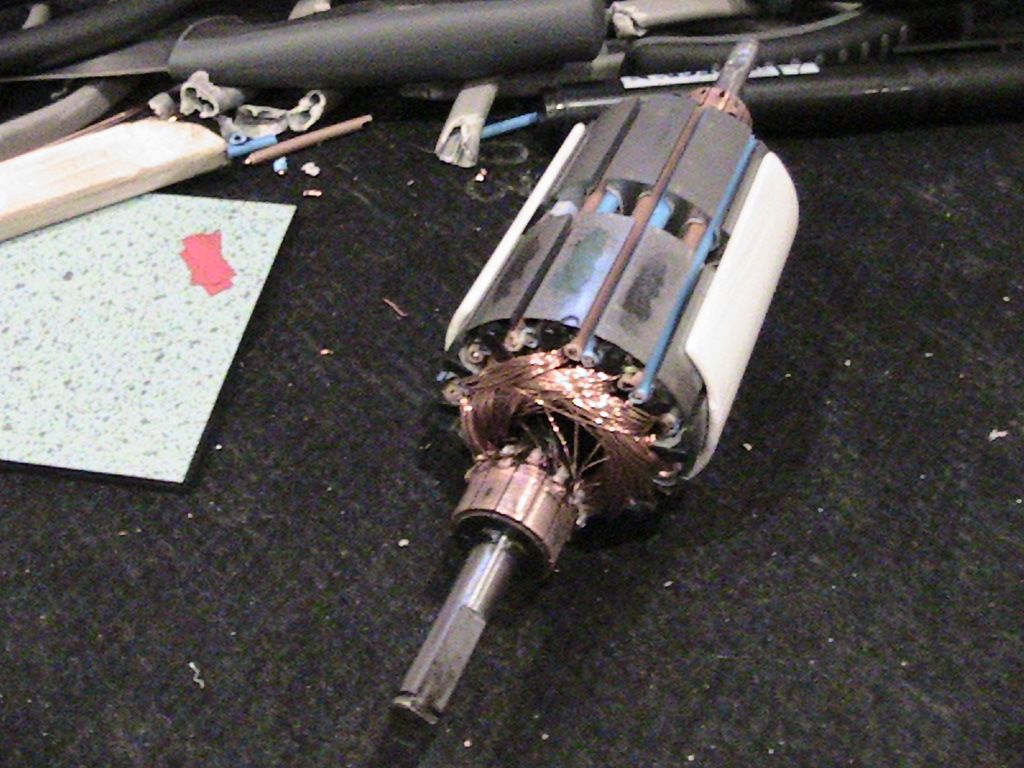
                                So I'm going to get a single sacrificial scooter motor and wind it with one comm and earth all bottom wires to the shaft and see what can be achieved.

                                Under this test one can either take out 7.40v or 17.40v if desired AND take the torque from the shaft.

                                When I tried to stall the OEM motor the 'beast' slowed in tandem but the amps draw looked somwhere in the 2A - 3A range (fluctuating).

                                Happy hunting

                                mark

                                Comment

                                Working...
                                X