Announcement

Collapse
No announcement yet.

My Asymmetric Electrodynamic Machines

Collapse
X
 
  • Filter
  • Time
  • Show
Clear All
new posts

  • Originally posted by HuntingRoss View Post
    [IMG][/IMG]
    Mark,

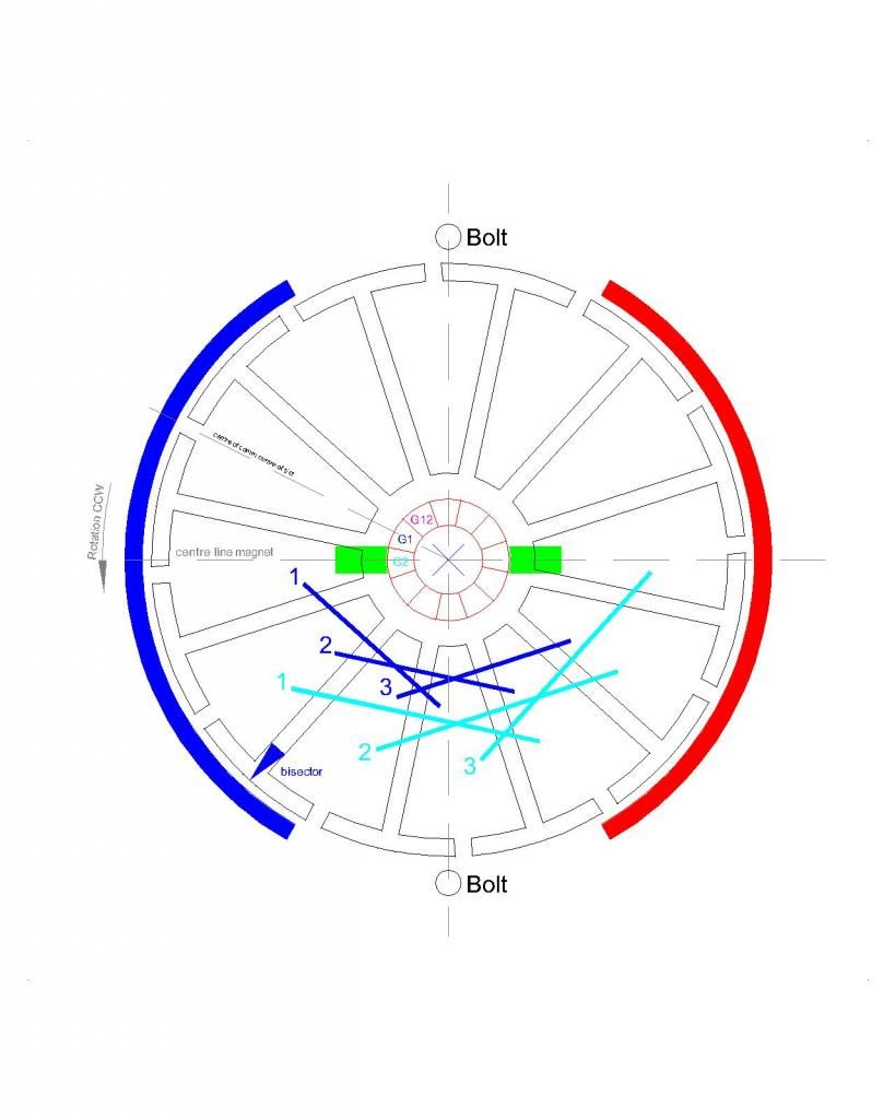
    Since your diagram is accurate, could you try your "quick and dirty" test like this? Set your G2 timing back/ccw 2 poles or just move the comm connection forward/cw 2 segments... The amps will be higher but by how much? And is the torque significantly stronger?


    Keep it Clean and Green
    Midaz
    Last edited by Midaztouch; 11-01-2014, 01:00 AM.

    Comment


    • Replication of UFOPOLITICS Asymmetric Dual Pentagon Y 5 Pole Motor by Lightworker1xxx

      Hello My Dear Friend UFO, Great Team, Ladies and Gentlemen.
      Let me present Part 1 YouTube Video about
      Replication of UFOPOLITICS Asymmetric Dual Pentagon Y Wind 5 Pole Motor

      Replication of UFOPOLITICS Asymmetric Dual Pentagon Y 5 Pole Motor by Lightworker1xxx - YouTube

      Thanks for watching

      Warmest Regards to All

      lightworker
      Last edited by Lightworker1; 11-01-2014, 02:09 PM.

      Comment


      • Originally posted by Midaztouch View Post
        Set your G2 timing back/ccw 2 poles or just move the comm connection forward/cw 2 segments... The amps will be higher but by how much? And is the torque significantly stronger?
        Hi Midaz

        I wish I had checked in this morning and seen your post...

        I decided for completeness and the interests of science to chop my 'quick and dirty' for a proper build. I have now built and tested that motor but will not report the results just yet as I would like to add to my data, my first attempts at torque testing the motors I now have littered on my table.

        If I'm understanding your request, the G1 Coil 1 would be just above the north bisector and the G2 Coil 1 would be just below the north bisector on that diagram ?

        If that is correct, it would be a simple task to jump the comm connections 2 segments CW once I have done my tests tomorrow...and hopefully add a torque test for this arrangement too.

        regards

        mark

        Comment


        • Originally posted by Lightworker1 View Post
          Hello My Dear Friend UFO, Great Team, Ladies and Gentlemen.
          Let me present Part 1 YouTube Video about
          Replication of UFOPOLITICS Asymmetric Dual Pentagon Y Wind 5 Pole Motor

          Replication of UFOPOLITICS Asymmetric Dual Pentagon Y 5 Pole Motor by Lightworker1xxx - YouTube

          Thanks for watching

          Warmest Regards to All

          lightworker
          G'Day Light
          I really enjoyed your setup it's been a lot of work in the making and easy to see all the parameters I cant wait to get back into my projects so as to finish them
          Kindest Regards
          Kogs
          Last edited by iankoglin; 11-02-2014, 04:32 AM.

          Comment


          • Lightworker

            Thank you for your vid. I see you put a lot of effort, time and planning in your setup. Could you explain why you connected capacitors to your motor winding?


            Keep it Clean and Green
            Midaz

            Comment


            • Originally posted by HuntingRoss View Post
              [IMG][/IMG]
              Hi Mark,

              Good morning in Japan and good evening in the states.

              Looking at the comm connection in your diagram, ONLY G2 is energized... Move the G2 timing forward 2 segments. The G2 coil1 would fire slightly after the north stator bi-sector.

              Keep it Clean and Green
              Midaz

              Comment


              • Torque Tests

                As promised for completeness. The figures for the single comm earth/ground shaft build -

                Using 0.425mm wire @ 0.121 ohm/m

                12 groups
                3 coils per group
                15 turns per coil
                All earthed to the shaft at the bottom of the groups

                I didn't do a resistance test per se but did a calculation based on metres used per group which is 5.2m giving approx 0.63 ohms.

                Connection this time was via both wires using the body as the output.

                10.34v PSU no load
                10.26v @ 1.04A @ 2280 rpm with 4.74v output.
                Stall amps approx 5.6A

                5.39v PSU no load
                5.16v @ 0.92A @ 1080 rpm with 2.64v output.
                Stall amps approx 3.4A

                For comparison. The OEM motor.

                10.3v @ 1.18A @ 1546 rpm.
                I couldn't pinch the shaft tightly enough to stall. Amps was 7A and rising.

                5.22v @ 1.18A @ 763 rpm.
                Stall amps approx 5.9A

                --S--

                The test today was to rig for measuring torque. It's rough and ready and serves as comparison between all 3 motors.

                The arm that I fabricated weighs 175g with the centre of mass 10mm from the shaft centre. Close enough that I discounted the arm from the calculations.

                The principle for operation was to manually support the arm perpendicular to the ground (floor) with the balance suspended from the arm and tethered to the ground. Switch the motor on and the balance would record the load applied by the stalled motor. The initial reading drops then stabilises, where, after 2 seconds the balance 'locks' and records the stable result.

                24v Battery (from scooter)

                OEM. 1.125kg @ 100mm [0.1125 kgm = 1.10 Nm]
                Single comm. 0.355kg @ 100mm [0.0355 kgm = 0.348 Nm]
                Beast (2 comm). 0.610kg @ 100mm [0.061 kgm = 0.598 Nm]

                The OEM is rated at 0.42 Nm @ 2500 rpm...not 1.10 Nm. What ever the reason for the discrepancy, for a baseline test the OEM has almost twice the torque of the Beast and four times the Single Comm.

                Keep hunting

                mark

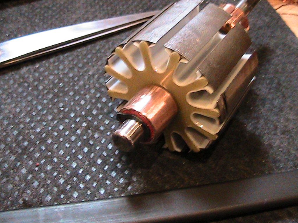
                [IMG]URL=http://s652.photobucket.com/user/huntingross/media/IMG_2762.jpg.html][/URL][/IMG]
                Pic of the copper collar at the base of the single comm motor.

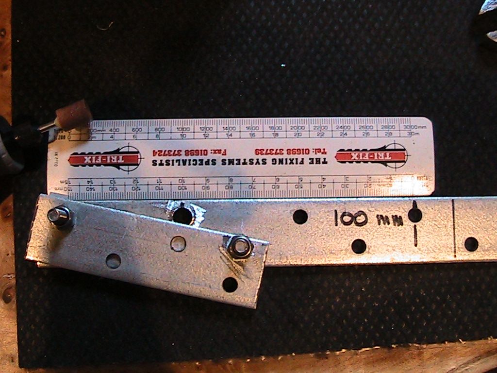
                [IMG]URL=http://s652.photobucket.com/user/huntingross/media/IMG_2764.jpg.html][/URL][/IMG]
                Pic of arm in fabrication.

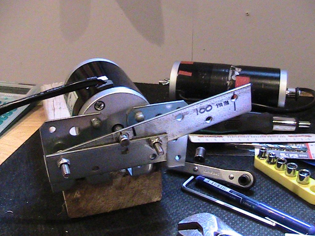
                [IMG]URL=http://s652.photobucket.com/user/huntingross/media/IMG_2766.jpg.html][/URL][/IMG]
                Pic of motor mounting bracket with arm attached to shaft.

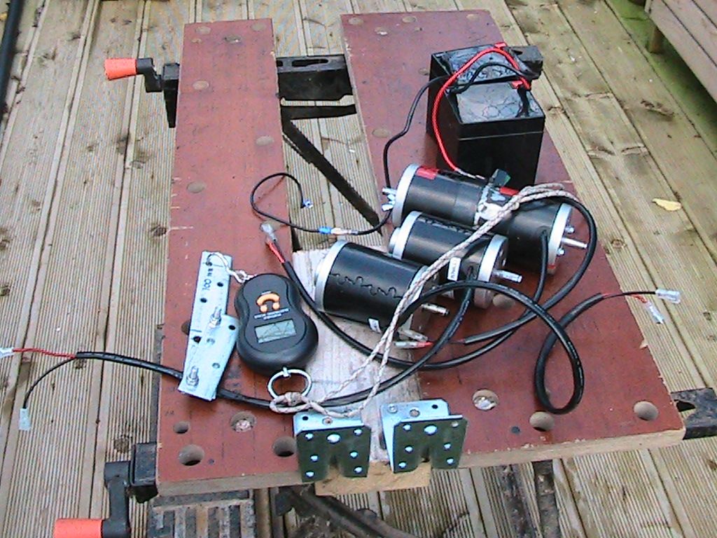
                [IMG]URL=http://s652.photobucket.com/user/huntingross/media/IMG_2768.jpg.html][/URL][/IMG]
                Pic of all 3 motors for testing.

                Comment


                • Mark

                  I see your kicking some serious butt, QUICKLY

                  I see two areas to increase the torque.
                  1.) Timing to the stator bi-sector.
                  2.) Can you add more turns to your coils

                  Time for some fine tuning

                  Keep it Clean and Green
                  Midaz

                  Comment


                  • Hi Midaz

                    The new build of the single comm is just one segment off your suggestion...not 2 as per the 'quick and dirty'...I set the timing back to my original diagram.

                    I was lucky in deciding on 15 turns per coil rather than my proposed 20 as it was really close to not getting the wedges in...at best I could do one or more per coil...I think as I get more used to winding motors I will be more efficient at layering the wire...but for now it is maxed out.

                    My next job is to strip the 'beast' and try and get it to equal the OEM...I have one idea for this...beyond that I don't know how to match the OEM which turns out to be quite a formidable little package...when it registered over 1kg today I was extremely surprised.

                    regards

                    mark

                    Comment


                    • Originally posted by HuntingRoss View Post
                      Hi Midaz

                      The new build of the single comm is just one segment off your suggestion...not 2 as per the 'quick and dirty'...I set the timing back to my original diagram.

                      I was lucky in deciding on 15 turns per coil rather than my proposed 20 as it was really close to not getting the wedges in...at best I could do one or more per coil...I think as I get more used to winding motors I will be more efficient at layering the wire...but for now it is maxed out.

                      My next job is to strip the 'beast' and try and get it to equal the OEM...I have one idea for this...beyond that I don't know how to match the OEM which turns out to be quite a formidable little package...when it registered over 1kg today I was extremely surprised.

                      regards

                      mark
                      Mark

                      Winging these motors is a labor of love! I had to wind the Imperial 4 times to get it right

                      Don't forget coil gauge must be factored in. Also, the group winding/lap winding focuses more on the generation of power. We can use other windings than that...

                      Keep it Clean and Green
                      Midaz

                      Comment


                      • Originally posted by iankoglin View Post
                        G'Day Light
                        I really enjoyed your setup it's been a lot of work in the making and easy to see all the parameters I cant wait to get back into my projects so as to finish them
                        Kindest Regards
                        Kogs
                        Thanks my dear friend Kogs.
                        My Prayers are with you that you are back to your R&D Passion ASAP.

                        Warmest Regards

                        light
                        Last edited by Lightworker1; 11-03-2014, 12:34 AM.

                        Comment


                        • Oscillating LC in Asymmetric Motors

                          Originally posted by Midaztouch View Post
                          Lightworker

                          Thank you for your vid. I see you put a lot of effort, time and planning in your setup. Could you explain why you connected capacitors to your motor winding?


                          Keep it Clean and Green
                          Midaz
                          Hello Midaz

                          Thanks for watching the video and appreciating it.
                          Here is a very simplified description of LC circuit instead of just Inductive Coil in our type of ASYMMETRIC MOTOR.

                          The circuit is oscillating entity. The energy in the universe can be written as E=hf where h is Planck's Constant and f the frequency.

                          It is true that even just a simple coil on its own has some self-capacitance.


                          In reality things are of course much more complex. In our motors other fields will also be playing their role.

                          Also at LC Resonance, interesting phenomena can also manifest.
                          For example, Tesla and Don Smith's OU systems use resonance.


                          The idea of LC has been discussed in this forum before.
                          See post #3920 by UFOPOLITICS 3 POLE_3 CAPS_10


                          It is an experimental idea. Furthermore, on the suggestion of UFO, the capacitor temperature monitoring system was put into place in this project as it has been noted by others before that heat death of capacitors is a possibility.

                          I hope this answers the question. Lets see where this idea of LC takes us to.

                          Warmest regards

                          light

                          Comment


                          • Originally posted by HuntingRoss View Post
                            As promised for completeness. The figures for the single comm earth/ground shaft build -

                            Using 0.425mm wire @ 0.121 ohm/m

                            12 groups
                            3 coils per group
                            15 turns per coil
                            All earthed to the shaft at the bottom of the groups

                            I didn't do a resistance test per se but did a calculation based on metres used per group which is 5.2m giving approx 0.63 ohms.

                            Connection this time was via both wires using the body as the output.

                            10.34v PSU no load
                            10.26v @ 1.04A @ 2280 rpm with 4.74v output.
                            Stall amps approx 5.6A

                            5.39v PSU no load
                            5.16v @ 0.92A @ 1080 rpm with 2.64v output.
                            Stall amps approx 3.4A

                            For comparison. The OEM motor.

                            10.3v @ 1.18A @ 1546 rpm.
                            I couldn't pinch the shaft tightly enough to stall. Amps was 7A and rising.

                            5.22v @ 1.18A @ 763 rpm.
                            Stall amps approx 5.9A

                            --S--

                            The test today was to rig for measuring torque. It's rough and ready and serves as comparison between all 3 motors.

                            The arm that I fabricated weighs 175g with the centre of mass 10mm from the shaft centre. Close enough that I discounted the arm from the calculations.

                            The principle for operation was to manually support the arm perpendicular to the ground (floor) with the balance suspended from the arm and tethered to the ground. Switch the motor on and the balance would record the load applied by the stalled motor. The initial reading drops then stabilises, where, after 2 seconds the balance 'locks' and records the stable result.

                            24v Battery (from scooter)

                            OEM. 1.125kg @ 100mm [0.1125 kgm = 1.10 Nm]
                            Single comm. 0.355kg @ 100mm [0.0355 kgm = 0.348 Nm]
                            Beast (2 comm). 0.610kg @ 100mm [0.061 kgm = 0.598 Nm]

                            The OEM is rated at 0.42 Nm @ 2500 rpm...not 1.10 Nm. What ever the reason for the discrepancy, for a baseline test the OEM has almost twice the torque of the Beast and four times the Single Comm.

                            Keep hunting

                            mark
                            Hello Mark,

                            Well, sorry to tell you, but there is definitively something wrong with your 'beast' my friend.

                            ALL the Asymmetrical Machines has been so far proven of much higher torque than any Symmetrical original, so either you have a timing issue or something else there.

                            About your build I will tell you about some things I don't like:

                            I do not like splitting the rotor and stators in two parts, so there is DOUBLE the rotor mass for the same amount of wire, considering there is absolutely no magnetic interactions at all between the Empty Gap, even though wires are running through it, there is no steel, no stators. This gap would not contribute to more output either...

                            And looking at the magnetic field pattern...you are creating a number eight (8) look alike shape....You must realize that the All North Machines generate the South Pole at the Steel Shaft...magnetism travels through diamagnetic's materials like copper without any influence nor blocking it...so that Gap of South Shaft attracts the North poles generated at rotor fascia, weakening it...that's why the number "8"

                            A fair approach to compare against the OEM would be to build SAME size Rotor, SAME size Stators...and SAME exact type of wire.

                            The second part I do not like is your 'calculated resistance'...if true, is way too low...I have repeated here that it MUST BE above 0.7 Ohms minimum per independent Group/Pair, and being 1.0 ohms the ideal scenario. A very low resistance could mean very poor/low magnetic field strength IF you are using a lower gauge wire than original, which is your case...plus a very low resistance per Interaction would definitively rise your amps draw sky high.

                            I really enjoy and appreciate your enthusiasm on building all this machines and providing all this testings...but at the same time I want you to do it right, in order to achieve satisfactory results towards the Asymmetry...like so many members here have proven so far.

                            Keep up the great work!


                            Kind Regards


                            Ufopolitics
                            Principles for the Development of a Complete Mind: Study the science of art. Study the art of science. Develop your senses- especially learn how to see. Realize that everything connects to everything else.― Leonardo da Vinci

                            Comment


                            • Thanks UFO

                              I understand the frustration of watching a Newbie stumble through the learning curve of a new subject but I do appreciate everyones patience and assistance, especially your helpful nudges to keep me 'straight'.

                              It was the torque test that crystalised my analysis of the 'beast' and I have a proposal to rewire that motor because I also suspect that something is 'going on' in the middle region. I might have that done for this weekend but this week is looking a little busy.

                              The 'beast' is not wired as a Figure 8 but I think you mean the 'interactions' rather than physically wound that way...I hope to address that point.

                              Best regards

                              mark
                              Last edited by HuntingRoss; 11-04-2014, 12:40 PM.

                              Comment


                              • Number Eight "Pattern"...

                                Originally posted by HuntingRoss View Post
                                Thanks UFO

                                I understand the frustration of watching a Newbie stumble through the learning curve of a new subject but I do appreciate everyones patience and assistance, especially your helpful nudges to keep me 'straight'.

                                It was the torque test that crystalised my analysis of the 'beast' and I have a proposal to rewire that motor because I also suspect that something is 'going on' in the middle region. I might have that done for this weekend but this week is looking a little busy.

                                The 'beast' is not wired as a Figure 8 but I think you mean the 'interactions' rather than physically wound that way...I hope to address that point.

                                Best regards

                                mark
                                It is OK Mark, is all part of learning...

                                The "Figure Eight" (8) is not about the winding, I know you did it straight...it is about the South Center Shaft exposed/open section, attracting-looping to the outer rotor Norths as they turn on...therefore, weakening them. This will not take place on a compacted top-bottom solid laminated rotor.

                                Now, if you compact the two rotors, and get stators together...then it would be unfair for the Symmetrical OEM, as magnetic fields will become stronger at the outer fascia. The best comparison would be an identical sized armature/rotor.

                                For your knowledge, the Imperial P56, have Eight Stators, but they are completely attached together vertically, mating South-South, North-North...at first look they seem just Four Stator-Magnets.

                                The "Compactness" of all components of an Electromagnet are very important for their field strength output.

                                1- Compactness of the Core Laminations.
                                2- Compactness of the wires configuring the coil(s)

                                When We wind a Coil, it is extremely important to keep a constant tension on wire AND to try NOT TO cross over wires, but to run them tight and very close/PARALLEL one to the other.

                                The windings should go as 'Layers' from interior to exterior, and then returning from exterior to interior (closer to shaft)...and so on.

                                Whenever I want to do a very accurate and precise winding I use a very fine, but very strong tape between each layer, I set the tape in the same direction of winding, so that when I pull tape I compact wire even more.

                                Every Coil and Group must be wound with same consistency and same winding procedure...this will generate identical fields strength when turned on, as well when they generate out.

                                This Concepts also apply for Generators Induced Coils/Fields.


                                Regards


                                Ufopolitics
                                Last edited by Ufopolitics; 11-04-2014, 08:38 PM.
                                Principles for the Development of a Complete Mind: Study the science of art. Study the art of science. Develop your senses- especially learn how to see. Realize that everything connects to everything else.― Leonardo da Vinci

                                Comment

                                Working...
                                X