Announcement

Collapse
No announcement yet.

My Asymmetric Electrodynamic Machines

Collapse
X
 
  • Filter
  • Time
  • Show
Clear All
new posts

  • Thanks UFO

    I thought about your 'figure 8' comment most of the afternoon and I get it now...It's like an hour glass.

    I don't think my proposal will fix that but I chopped the beast tonight and will do a couple of 'quick and dirty' builds with just a few turns to get a feel for what I think might be happening inside.

    I'll re-build it with your 'winding tips' in mind to try and improve the quality of my layering and see how it performs. If my calculations are correct the proposed re-build should put the resistance up around 1.25 ohms per group.

    I don't want to ditch the motor as a learning tool just yet as it interchanges so quickly with the OEM in the scooter. I would say the 'beast' is in its middle age with retirement just around the corner though.

    Best regards

    mark

    Comment


    • My pleasure...

      Originally posted by HuntingRoss View Post
      Thanks UFO
      My pleasure Mark, it is really great to assist Members like you my friend..."Go getter's"....Makers...stubborn (in the good sense)...your perseverance and insistence is amazing.

      I thought about your 'figure 8' comment most of the afternoon and I get it now...It's like an hour glass.
      Exactly right...

      I don't think my proposal will fix that but I chopped the beast tonight and will do a couple of 'quick and dirty' builds with just a few turns to get a feel for what I think might be happening inside.

      I'll re-build it with your 'winding tips' in mind to try and improve the quality of my layering and see how it performs. If my calculations are correct the proposed re-build should put the resistance up around 1.25 ohms per group.

      I don't want to ditch the motor as a learning tool just yet as it interchanges so quickly with the OEM in the scooter. I would say the 'beast' is in its middle age with retirement just around the corner though.

      Best regards

      mark
      Well, you may be amazed what a middle age guy like that could do...

      It is a matter of time for you to get everything straight forward...and burning rubber...


      Regards


      Ufopolitics
      Principles for the Development of a Complete Mind: Study the science of art. Study the art of science. Develop your senses- especially learn how to see. Realize that everything connects to everything else.― Leonardo da Vinci

      Comment


      • Mark

        Hang in there! Your doing great! At the rate your going, you will be spot on in a few weeks!

        I wish your "quick and dirty" setup had two comms and you set the timing like UFO said at the very beginning. Then there would be very little discrepancies, just fine tuning.

        Keep pushing

        Midaz
        Last edited by Midaztouch; 11-06-2014, 01:34 AM.

        Comment


        • Thank you for the encouragement gentlemen.

          Once again in the interests of science..."I have not failed. I've just found 10,000 ways that won't work." Thomas A Edison.

          After the last tests to demonstrate relative torque between 3 motors. It seemed apparent that something was amiss with the 'beast'. On reflection the main difference with other reported motors was the middle gap between laminations.

          Before I abandon this motor, I hatched a plan to rewind in a way that I thought would strengthen the field around the upper and lower laminations respectively.

          I completed the build late last night and tested it just a short while earlier.

          A 10v PSU torque test between OEM and Beast #2.

          OEM. 0.655kg @ 100mm. Stall amps 9.6
          Beast #2. 0.200kg @ 100mm. Stall amps 8.3

          So my nifty idea didn't work.

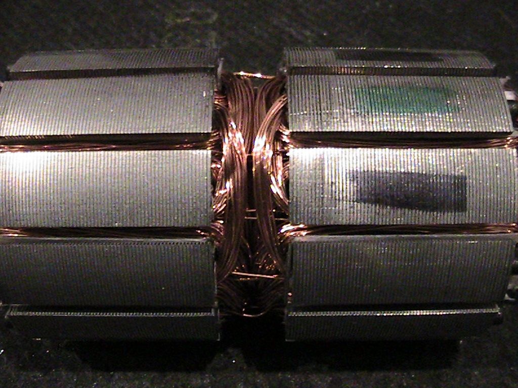
          The images below shows the completed wind. Each group was checking out at 0.8 ohms.

          [IMG][/IMG]

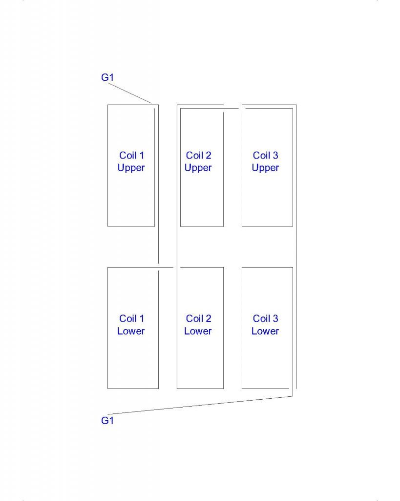
          Now. I've tried to understand the notation for drawing motor winds and I find it confusing. So if you can follow my sketch, it goes like this. These are all north. Wind Coil 1 upper then drop down to Coil 1 lower then over to Coil 2 lower then up to Coil 2 upper then over to Coil 3 upper then down to Coil 3 lower. The coils lap in the same way as usual each coil advancing one pole from the last.

          This is a 12 group motor with 3 poles per coil. This is one group.

          [IMG][/IMG]

          The next version of the beast will be cut down with no gaps and a reduced body length as described by UFO and replicated by others.

          Carry on hunting

          mark

          Comment


          • Mark,

            Thank you for your effort... Just wire the upper section for now. Your beast still has two comms. Let's see if that give you better results

            Are you understanding the time better?

            Keep it Clean and Green
            Midaz
            Last edited by Midaztouch; 11-07-2014, 04:50 AM.

            Comment


            • After much re-engineering and rebuilding. I introduce Beast #3.

              No middle gap in the armature, 11 turns 3 poles per coil, 3 coils per group, 12 groups. This is salvaged wire from the 12 turn Beast #1 which built #2 with 9 turns...so I'm losing length each time !!

              From above -
              A 10v PSU torque test between OEM and Beast #2.

              OEM. 0.655kg @ 100mm. Stall amps 9.6
              Beast #2. 0.200kg @ 100mm. Stall amps 8.3
              Todays results -
              10.34v PSU no load
              10.21v @ 1.60A @ 3210 rpm with 8.45v out
              0.220kg @ 100mm. Stall amps 9.0.

              The only thing that would distinguish this build from other replications is I have the stators from both original motors welded back to back.

              To remove that anomaly I would have to either remove one set of magnets from the build or turn them around to be front to back and thereby eliminating the repulsion force in the middle.

              I need to ponder how to achieve that.

              mark

              Comment


              • Originally posted by Ufopolitics View Post
                Hello to All,

                Guys, You know me by now...and I would not "sacrifice" all I have displayed here, Criticize my own work rendered here for about two years...unless I will be giving you ALL something MUCH better in Quality, Quantity and Performance...Something "beyond"...

                And what really bothers me...is that I (and We all) had it all this time right in front of me (and in front of You too Guys)...but I (or we all) could not see it!!

                Remember this little Motor?...My First exposed here because of being made out of Three Poles?

                [IMG][/IMG]

                You could go back on this Thread and look how many times I mentioned about the "greatness" of this type of little Machine.

                Then I jumped to this one...The Five Poles Radio Shack:

                [IMG][/IMG]

                What MAIN, BIG TIME difference You guys see right in front of our noses...besides the obvious Pole Number of 3 and 5?

                Basically am referring to Rotor windings difference...

                Simple...the Three Poles does NOT have North-South Pairs rotating within same SPACE RING...They are ALL North Poles...or could be ALL South if we reverse the Input.

                When they are all North...Their related South poles are ALL Projecting towards shaft...and viceversa...

                The point is...NEVER an opposite Pole will take the SPACE of the other...so ALL NORTHS will ALWAYS be rotating while projecting their fields OUTWARDS...while ALL Souths would be projecting field INWARDS towards shaft...

                The Five Pole...or any of the following Higher Poles Models repeat the same attributes the Three Poles had.

                Why the difference? ...Does it makes that much of a change?

                YES!!

                By rotating same polarity at Interacting ends (Eg All Norths)...it takes very little to "enhance" (refill) again the Solid North at times to be fired...no South or reverse flux generated within Steel Cores, and that acts like a transformer here, where all flux travels through and collides every time each opposite pole takes the SPATIAL Positioning of the previous opposite one...

                [IMG][/IMG]

                Something "similar" to this 3D Diagram...but with the South at center of Cylinder, as also comprehending shaft.

                Whenever We use a South next to a North (Symmetry does it at all times...and so we also did except in the Three poles) we get the example below:

                [IMG][/IMG]

                And My way to know for sure was pretty simple:

                Two RS Motors, Five Poles...One, like the Typical P5 shown on above diagram...using EXACTLY SAME awg and number of turns...I wound a Five Poles with ALL NORTH Poles at rotor...that's it.

                [IMG][/IMG]

                No more Red Lines...or Yellow or Orange...all BLUE or Pale Blues meaning at Motor Stage...vivid dark Blues are being fired...while lighter blues are off the brushes...Then All Greens shades are at Generator Ends...

                And of course...using a PSU...Same Input as V & A...plus measuring all parameters like output, RPM's, Torque...plus listening to the smoothest drive ever...sweeet

                This type of Homopolar or Unipolar Rotors...can only be achieved by taking the Asymmetries we had before...to an even more radical asymmetry... my friends...

                I know it may sound weird to many...but it is the GOD Honest truth Guys.

                Well...am pretty sure many of you...with your experience by now at winding...could do this little machine in very short time...trust me is worth it... but please, do not take apart the original P5...so could be compared.


                Regards to All


                Ufopolitics
                Ufo,

                I asked questions about this statement before but they weren't answered...

                3pole has three separate Uni-Polar Coil. It's focused on repulsion, attraction is secondary. Plus you got max turns.... 5pole has Uni-Polar Coil "Pairs". Paris focuses in on attraction and repulsion. Attraction takes coil turns away from repulsion. Attraction is weak?!

                Why didn't the 5pole have five separate Uni-Polar coil, just like the 3Pole? Why did you make pairs? How is the gen action affected?


                Keep it Clean and Green
                Midaz
                Last edited by Midaztouch; 11-14-2014, 04:56 AM.

                Comment


                • Originally posted by Midaztouch View Post
                  Ufo,

                  I asked questions about this statement before but they weren't answered...

                  3pole has three separate Uni-Polar Coil. It's focused on repulsion, attraction is secondary. Plus you got max turns.... 5pole has Uni-Polar Coil "Pairs". Paris focuses in on attraction and repulsion. Attraction takes coil turns away from repulsion. Attraction is weak?!

                  Why didn't the 5pole have five separate Uni-Polar coil, just like the 3Pole? Why did you make pairs? How is the gen action affected?


                  Keep it Clean and Green
                  Midaz
                  Midas, referring to the 2 five leg drawings above, are you saying the top drawing shows 4 legs wound north and south to form 4/5 of the armature having two legs each north and south? while the second picture shows 3 legs wound to form 3/5 of the armature to form a single pole? There's a big difference between the two windings. In the early posts several people including myself wound the first motor all north and it didn't work and we where made fun of for making the mistake, but it all makes sense. 4 legs all producing the same pole is to many to work right? By the way when I wound the RS motor all north as shown back around the 6957 post I had similar results to what I think Mark mentioned as it pertained to less power than the original. I will admit, as you say, it was smooth but the power wasn't there for me. This is the same winding on the 6957 and here right? UFO, no one would dispute your build so why don't you provide the comparison between the two motors? All you need is a small propeller and a prop adapter along with about 15 minutes of your time to test the two motors.
                  John
                  Last edited by DadHav; 11-14-2014, 05:19 PM.

                  Comment


                  • Originally posted by DadHav View Post
                    Midas, referring to the 2 five leg drawings above, are you saying the top drawing shows 4 legs wound north and south to form 4/5 of the armature having two legs each north and south? while the second picture shows 3 legs wound to form 3/5 of the armature to form a single pole? There's a big difference between the two windings.
                    That is correct
                    4 legs all producing the same pole is to many to work right?
                    I think so
                    By the way when I wound the RS motor all north as shown back around the 6957 post I had similar results to what I think Mark mentioned as it pertained to less power than the original. I will admit, as you say, it was smooth but the power wasn't there for me.
                    By the nature of this NN wind & timing, it looks like it should be less torque than the NS
                    This is the same winding on the 6957 and here right? UFO, no one would dispute your build so why don't you provide the comparison between the two motors? All you need is a small propeller and a prop adapter along with about 15 minutes of your time to test the two motors.
                    John
                    Hi John

                    Looking at P1 on both 5pole images above

                    The NS and NN motors have two winds at P1. I think that P1 should be one north wind that covers two poles/legs.
                    One wind would give more space to use a thicker gauge wire with about the same number of turns
                    focused on the repulsion force. Also staying near the specs of .7 ohms resistance.

                    P1 ~ P5 should have one coil wind each.

                    *For "fair testing", use the same wire gauge as the factory motor
                    *This would be a third option for asymmetric motors @ 2/5

                    RPMs under load? More torque under load? Does it still generate comparable power/voltage?

                    Keep it Clean and Green
                    Midaz
                    Last edited by Midaztouch; 11-15-2014, 01:13 PM. Reason: Got some time to answer John's questions

                    Comment


                    • Some activity to report

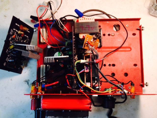
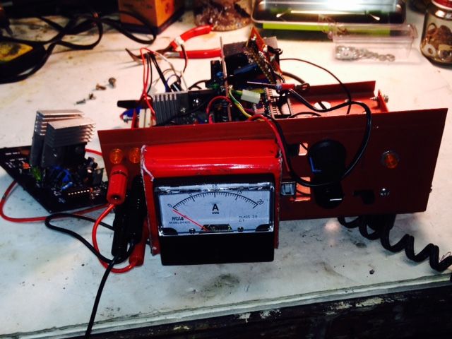
                      Hey gang, been hanging out on the my-motors thread building my AMC (Asym. Motor Controller). Burnt out a mosfet pretty quick going to a 30v power supply on a broke motor not-ready-for-prime-time, hung brush, and brush hanging by a copper strand. Left the power up at max when I switched off the 12v supply, fried a FET in an instant.

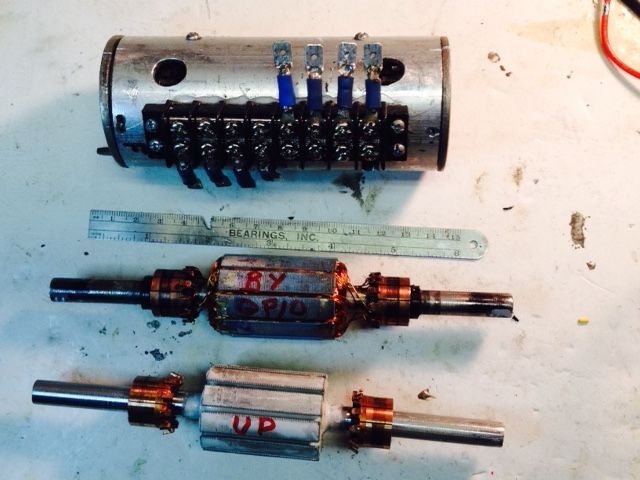
                      SOOOO patching my boards to do quad FETs, note this pic has the one board on the left with TWO heat sinks. That will go on the inside. Then I will put two FETs on the bottom of the other board and cut a hole in the side of the cover. Note the fan at the bottom on the left. Only room for three heat sinks there when reconfigured.


                      New panel meter on the front, will just measure one circuit, up to 20A.


                      Planning a Quad unipolar on my GM window motors. This one ran hot around 8000 rpm on the Bent Y Quad Pentagon 10-pole winding (blue rotor), under one ohm per coil, hit 130deg. Planning to litz the white rotor on 2-32ga about 16", wound kinda tight to get more resistance, maybe over 1 ohm. Gotta build two more boards too...


                      Will use this winding

                      Last edited by sampojo; 11-15-2014, 05:47 AM.
                      Up, Up and Away

                      Comment


                      • Wrong understanding...leads to wrong conclusions...

                        Originally posted by Midaztouch View Post
                        Ufo,

                        I asked questions about this statement before but they weren't answered...
                        Hello Midaz,

                        Sorry, I missed those questions...thought I did respond...but let's do it now.

                        (1)3pole has three separate Uni-Polar Coil. It's focused on repulsion, attraction is secondary. Plus you got max turns.... 5pole has Uni-Polar Coil "Pairs". Paris focuses in on attraction and repulsion. Attraction takes coil turns away from repulsion. Attraction is weak?!
                        (1)That is a WRONG Understanding Midaz:

                        The Three Pole has 50/50 Attract/Repulse

                        If you look again at the N1 being fired, plus the circumference of the commutator element....then you realize N1 starts with majority of Repulse....then as it gradually moves towards the CENTER/NEUTRAL POINT as IS SET IN DIAGRAM ABOVE, then N1 starts (from that point on) to Higher Percentage of ATTRACT Mode, while Repulsion decreases because getting further from Source.

                        As long as We have North-South Stators in ANY given Motor, We'll ALWAYS have at least a portion of Attract Mode.


                        I have tested ALL NORTH STATORS as well (In order to be based ONLY on Repulse)...it DON'T WORK.

                        Attraction is NOT weak at all, Attract-Repulse are Two completely different forces.

                        Repulse is an ENDLESS, NOT LIMITED Force while Attraction IS LIMITED by the attraction SOURCE, reaching too close this "Space Limitation" renders bad or weak Motor performance.

                        Attraction REQUIRES to be turned OFF, BEFORE reaching the Attract Source Space.
                        Repulsion is a PUSH FORCE that is born from the Source, so, it is not limited at all.

                        Using BOTH FORCES with proper Timing is an advantage to obtain better performance...In the case of our ALL NN Motors, REPULSE is our starting or "Ignition" Force and Attract is our Assisting or Secondary Force. Both Forces are ALWAYS utilized.

                        Why didn't the 5pole have five separate Uni-Polar coil, just like the 3Pole? Why did you make pairs? How is the gen action affected?
                        If You look at the CIRCUMFERENCE LENGTH of the Three Pole COMPARED to the CIRCUMFERENCE LENGTH of the Stators, You will realize they are exactly or about the SAME OR VERY CLOSE LENGTH.

                        Unfortunately, this ratio does NOT happen on the Five Pole...due to its Geometry...and so on...the more number of poles Machines...the more teeth/poles we will need to include/comprehend in our coils,pairs or groups to EQUALIZE the LENGTH OF STATOR(S). Then We are FORCED to OVERLAP Coils, Pairs or Groups... in order to reach ROBUST and CONSTANT Rotation, Power and Speed in smaller Time Frames.

                        The Protocols of Motor's Magnetic Interactions MUST comply with this rule, meaning, EQUAL or about the same CIRCUMFERENCE LENGTH between STATORS and ENERGIZED/INTERACTING ROTOR COILS.

                        This Protocol rule obeys to TWO MAIN facts:

                        1- The Intensity/Strength of Both Interacting Magnetic Fields (Rotor and Stators) MUST BE BALANCED, towards EQUAL FORCES.

                        2- The TRAVELING CIRCUMFERENCE from ON to OFF (Energizing On to Turning Off Coils, Pairs or Groups), MUST comply with the Commutator's Elements Circumference, in order to apply this Actions at the perfect Timing. This will prevent from Rotor to "tend" to approach too much to a LOCKING POSITION (BISECTORS MATCH), that will kill performance, even if Rotor does not get to lock position, but close enough.

                        So, if We wrap the Five Pole Motor (as an example) with Individual Coils (per each pole, or five SMALLER coils)...it simply will NOT work because the two facts written above.

                        Keep it Clean and Green
                        Midaz
                        Hope You understand all this post/explanation Midaz.

                        Only experience/practice in building several motors of different sizes, poles, etc...leads you not to assume, nor get to wrong conclusions..."this way could be better" or "could it be done this way...?"...etc,etc.


                        Regards


                        Ufopolitics
                        Last edited by Ufopolitics; 11-15-2014, 01:34 PM.
                        Principles for the Development of a Complete Mind: Study the science of art. Study the art of science. Develop your senses- especially learn how to see. Realize that everything connects to everything else.― Leonardo da Vinci

                        Comment


                        • Ufo,


                          I'm learning as we go but... Let me see if I'm getting this straight. If P1 is wind north using 2 poles then connected to the comms and using the factory brush settings then P2, P3 - P5 the same... the motor won't work

                          It doesn't make sense to me

                          It seemed to me that the motor should run fine the way I propose... Well, the only motor I've built is the Imperal NS. Yes, I need more building experience


                          Keep it Clean and Green
                          Midaz
                          Last edited by Midaztouch; 11-15-2014, 11:19 PM.

                          Comment


                          • Very short answer/question for a very long explanation......

                            Originally posted by Midaztouch View Post
                            Ufo,

                            I'm learning as we go but... Let me see if I'm getting this straight. If P1 is wind north using 2 poles then connected to the comms using the factory brush settings then P2, P3 - P5 the same... the motor won't work

                            It doesn't make sense to me


                            Keep it Clean and Green
                            Midaz

                            Midaz,

                            On your previous post you wrote:

                            Why didn't the 5pole have five separate Uni-Polar coil, just like the 3Pole? Why did you make pairs? How is the gen action affected?
                            I understood that question as making Five SEPARATE Coils, One Coil per each Pole (Unipolar Coil), as the Three Poles is built.

                            Am I right up to here?

                            I made "Pairs" because of the SIZE LENGTH in Rotor Coils versus Stators LENGTH...are you reading me or just trying to get your answer(s) while ignoring my explanations?

                            And if you are referring to wrapping just One Coil per Two Poles, STILL, you will be forced to Overlap them.


                            But, I have a better suggestion Midaz...why don't You build it, then test it and compare it to the Typical build?


                            Is the only and real way to know.


                            Regards


                            Ufopolitics
                            Principles for the Development of a Complete Mind: Study the science of art. Study the art of science. Develop your senses- especially learn how to see. Realize that everything connects to everything else.― Leonardo da Vinci

                            Comment


                            • Ufo

                              I'm bored! I want to build something but I only motor I have is the huge Imperial. Copper wire and test equipment are super expensive & special order in Japan!

                              The used stuff is just a few dollars less but very outdated and witten in all Japanese. Japan is run by giant tech companies and Universities.


                              Don't worry, I will reread you answer several more times
                              Last edited by Midaztouch; 11-17-2014, 04:57 AM.

                              Comment


                              • Testing comparisons...

                                Originally posted by HuntingRoss View Post
                                After much re-engineering and rebuilding. I introduce Beast #3.

                                No middle gap in the armature, 11 turns 3 poles per coil, 3 coils per group, 12 groups. This is salvaged wire from the 12 turn Beast #1 which built #2 with 9 turns...so I'm losing length each time !!

                                From above -


                                Todays results -
                                10.34v PSU no load
                                10.21v @ 1.60A @ 3210 rpm with 8.45v out
                                0.220kg @ 100mm. Stall amps 9.0.

                                The only thing that would distinguish this build from other replications is I have the stators from both original motors welded back to back.

                                To remove that anomaly I would have to either remove one set of magnets from the build or turn them around to be front to back and thereby eliminating the repulsion force in the middle.

                                I need to ponder how to achieve that.

                                mark

                                Hello Mark,

                                It seems you still have Two rotors and two stators attached/stacked vertically on all your "Beasts" testings...while having every time much less wire to wrap coils...

                                One thing you most realize: Symmetrical Motors Energize ALL Coils in the Armature/Rotor every second of rotation, meaning, at all time...they divide N-S through the plane derived from the brushes position. So, every time one coil passes this plane it will reverse polarity from previous one.

                                Second, You are using MORE MASS of Rotor for about the same type of wire, with lesser turns.


                                Why don't you try the following:

                                Build an Asymmetrical Motor with SAME, EXACT sized Rotor as OEM, and SAME, EXACT STATORS LENGTH as OEM. This way You will have the same Steel Mass to rotate as OEM.

                                Use as many turns as you could possible be able to fit on the Rotor Space allowance per each Coil/Group.

                                Try to use SAME or Higher Gauge wire (coarser, thicker) than OEM.

                                If this still will keep Asymmetric under OEM in your tests...then we will move to All North Pairs, not Groups of Three, but just Two Coils, and I will give you detailed Diagrams...but using same space, except you will be wrapping Two Coils using the spacef your previous Three Coils took...this will strengthen concentrate the magnetic field bisector/higher density ...while you could use more wire.

                                To me it seems an issue with very weak magnetic fields on rotor what is rendering those results, it could be due to few issues...One and main...too little wire (too small amount of turns per coil(s))...and on top of that you have more mass/weight to rotate due to double rotor attached together...while STRONGER Magnetic Fields coming from Dual, vertically stacked together Stators. That is why I suggested to go for same structure as OEM.


                                Regards


                                Ufopolitics
                                Last edited by Ufopolitics; 11-15-2014, 03:11 PM.
                                Principles for the Development of a Complete Mind: Study the science of art. Study the art of science. Develop your senses- especially learn how to see. Realize that everything connects to everything else.― Leonardo da Vinci

                                Comment

                                Working...
                                X