Announcement

Collapse
No announcement yet.

My Asymmetric Electrodynamic Machines

Collapse
X
 
  • Filter
  • Time
  • Show
Clear All
new posts

  • Hi UFO,
    Been admiring your work but am not much of an electrician. Is there anyone in S. Florida that winds motors asymmetrically? I have an 8K watt generator that I would like to convert to your specs - nice to be ready for next hurricane season.

    Love your work,
    Paul

    Comment


    • Do they have junkyards in Japan?

      Originally posted by Midaztouch View Post
      Ufo

      I'm bored! I want to build something but I only motor I have is the huge Imperial. Copper wire and test equipment are super expensive & special order in Japan!

      The used stuff is just a few dollars less but very outdated and witten in all Japanese. Japan is run by giant tech companies and Universities.


      Don't worry, I will reread you answer several more times
      Hey Midaz, thats why I switched to salvaged car window motors. I had to refurb my blower motor on one of my cars and started salivating on the asym motor possibilities there. But blower motors are a little more expensive, but a nice size, bigger, easy to work with compared to hobby motors, and just may generate enough power to prove something... So the racing motor didn't work out? got fried in Ohio didn't it?
      Up, Up and Away

      Comment


      • "Finding free energy is no longer on my bucket list."

        Originally posted by DadHav View Post
        Ha, you got that part of it right. Old Dudes can be shorter of time than you can even imagine not to mention stubborn. You should have seen the people I inherited it from. It's pretty important that we "Old Dudes" spend time doing things we enjoy, especially with family and friends. Finding free energy is no longer on my bucket list. Having fun and enjoying building things still is. #Not remembering things the way you used to #Not wanting to share something that isn't a real life application yet #Not wanting to waste peoples time and use up what small time you have left by leading a thread #Doing things your own way #Doing things when you want to do them. I don't think this is an unreasonable approach for an Old Dude. But thank you for inviting me to continue building "whatever" motor I was talking about. I'll go back through my mail to refresh my amnesia, I mean memory. It might be what I'm thinking about now. You made me sorry I ever had conversations with you. I promise you, if I end up with something worth while I'll quickly share the information with my friends.
        Cheers Richie
        J

        Finding free energy is no longer on my bucket list.

        That Statement above says it all... doesn't it guys?


        Cheers


        Ufopolitics
        Principles for the Development of a Complete Mind: Study the science of art. Study the art of science. Develop your senses- especially learn how to see. Realize that everything connects to everything else.― Leonardo da Vinci

        Comment


        • Conversions...

          Originally posted by reidrider View Post
          Hi UFO,
          Been admiring your work but am not much of an electrician. Is there anyone in S. Florida that winds motors asymmetrically? I have an 8K watt generator that I would like to convert to your specs - nice to be ready for next hurricane season.

          Love your work,
          Paul
          Hello reidrider,


          Thanks, but a Generator can not be converted to a Motor...nor to an Asymmetrical Machine either, my friend.

          And, based on my knowledge...I do not know of anyone who winds motors asymmetrically -as a "established" business- in South Florida...

          However, there are Threads here dedicated to do just that...convert Generators in order to avoid Lenz Law (counter reaction forces)...so they could be run by any Motor. That Thread is very young and they are just building small scale models for testing...so, hang in there...


          Regards


          Ufopolitics
          Principles for the Development of a Complete Mind: Study the science of art. Study the art of science. Develop your senses- especially learn how to see. Realize that everything connects to everything else.― Leonardo da Vinci

          Comment


          • Originally posted by sampojo View Post
            Hey Midaz, thats why I switched to salvaged car window motors. I had to refurb my blower motor on one of my cars and started salivating on the asym motor possibilities there. But blower motors are a little more expensive, but a nice size, bigger, easy to work with compared to hobby motors, and just may generate enough power to prove something... So the racing motor didn't work out? got fried in Ohio didn't it?
            Hello Sam,

            The Imperial that Dana did was connected wrong, it did not get fried, but some damage did happen, and am not familiar exactly what was it.

            But Midaz , Dana and I, posted here all conclusions and pictures a while back...what happen?...you did not read it?

            I will be winding an Imperial to be tested there...same place, so will see results sometime in the beginning of the year.

            I am busy working on a new material to be disclosed before the end of 2014, and can not do it at this moment.

            By the way, I have been following the progress with your Monster Driver plus some of your Machines...did you ever finished the big Baldor two Stators?


            Regards friend


            Ufopolitics
            Last edited by Ufopolitics; 11-26-2014, 12:28 PM.
            Principles for the Development of a Complete Mind: Study the science of art. Study the art of science. Develop your senses- especially learn how to see. Realize that everything connects to everything else.― Leonardo da Vinci

            Comment


            • No, Hitby...I have not...

              Originally posted by Hitby13kw View Post
              UFO & Team – Can't wait for the new release . . . but maybe I should . . .
              Many apologies for being off the grid and not at my home lab for so long. Sometimes life is like that and we are unable to control the circumstances, but that’s another story for another time and place.

              Now is the time to get serious with this new All North winding configuration up scaled to the Imperial. To that end we have already contacted Dyann and have an unblemished shaft-rotor and new Commutators in hand.

              Have a few " honeydos " left to catch up on before we get free time in the shop, but we are close.

              UFO have you developed any other pictures of the winding sequence for the Imperial other than what you’ve already posted?

              Been trying to keep up but may have missed something important.

              Hitby13kw


              Hello Hitby!...long time Friend!

              The only drawings I have done in the Imperial All North are on This Album

              There I have both ways to wind it:

              In All North Groups:

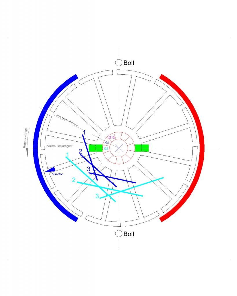
              [IMG][/IMG]

              This is a basic Diagram of the FOUR MAIN GROUPS at "work"...each Group has Six Coils and each coil wraps around FIVE POLES, exactly the way Imperial Symmetric comes from factory. (remember that previously on the N-S Pairs we did it with SEVEN POLES.


              In All North Pairs:

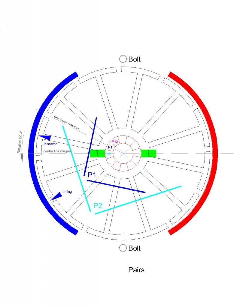
              [IMG][/IMG]

              In Pairs, the two Coils also wrap around Five Poles, and the Pair sequence comprehends Ten(10) Poles as well as the Total Poles in the Overlapped Six (6) Coils in the Group Winding.

              Now, Hitby, I don't think anyone has built-so far- the Imperial All North (in either config's) as up to now (unless some silent member(s) has done it and we don't know).

              Midaz and I have exchanged a few Mails about number of turns per coil (in the Group, in the Pairs I would try to do same as before...meaning around 13-15 turns per Coil, and I will love to be able to do 30 total [15 per coil in pair] just like Kogs built his N-S Pairs that ran so well here).

              In the Group Winding, I believe -if my "amnesia" don't show up...- that We should try to do -at least- FIVE TURNS PER COIL...Totaling 30 turns per Group (6x5=30) (same as Total Pairs).

              The Basic Timing Diagram -on Pairs- is below:

              [IMG][/IMG]

              Again, I have not done this winding yet...so, I don't have any details in reality...and as we all know...only Lab Building will give us the right answers related to space/room and perfect timing alignment.

              I have a Full Kit ...plus a Rotor Kit (some minor damage on both, that I have to epoxy on rotor plates and smooth some light scratches on Commutators)....and I am planning to build both winding sets in those Two Rotors to be tested against the Mecc Alte Generator Head 6K.

              If You want to start based on this Diagrams...any questions/doubts -during process- would be very welcome anytime my Dear Friend.


              @All: If Anyone have done this winding, please, post results here to lead the rest...it would be highly appreciated .Thanks.


              Kind Regards Hitby!


              Ufopolitics
              Principles for the Development of a Complete Mind: Study the science of art. Study the art of science. Develop your senses- especially learn how to see. Realize that everything connects to everything else.― Leonardo da Vinci

              Comment


              • Originally posted by Ufopolitics View Post
                That Statement above says it all... doesn't it guys?


                Cheers


                Ufopolitics
                As it pertains to my comment "Free energy is no longer on my bucket list"
                A bucket list is usually things you would like to do before you kick the bucket right? Sometimes in life the list of things you would like to do must be replaced with a list of things you have to do. I said I'd continue to experiment when I have time, but I'll do it for fun and hobby value. If anything along the way looks like it's energy saving or unique in any manner then that only adds a plus sign to something that was already enjoyable.
                Cheers, good luck with your next project.
                John
                Last edited by DadHav; 11-26-2014, 02:01 PM.

                Comment


                • Beast Build #5

                  Originally posted by HuntingRoss View Post
                  Beast #4. One stator. 2 comms back-to-back rotors (bonded) no gaps.

                  Wound as all north pairs...and salvaged from Sunday's abortive test by ONLY re-hooking the comms to adjust the timing. This motor requires to be re-wound to be (3+3)...It is currently (4+4)

                  14 turns 4 pole per coil...28 turns per pair...12 pairs...0.8 ohms per pair.

                  10.35v PSU no load
                  9.6 - 3.0v @ 4.50A @ 8215 rpm with 4.8 - 1.9v out

                  No torque test tonight.

                  The voltmeter readings were jumping all over the range and the motor was steadily warming up...I'm assuming arcing is the problem here.

                  The acceleration was slow starting and torque on a simple resistance test was quite low. The timing is too close to attraction and could be retarded by 2 segments (maybe 3).
                  The torque test for this motor before I chopped it was -

                  160g @ 100mm

                  So. Moving on to Beast Build #5

                  0.5mm wire @ 0.0871 ohm / m
                  12 all north pairs
                  25 turns 3 poles per coil - 50 turns per pair @ 0.9 ohms
                  10.33v PSU no load
                  10.14v @ 1.71A @ 4840 rpm
                  5 minute run time with some warming of motor
                  10.19v @ 1.51A @ 4870 rpm
                  8.04v out
                  Torque 160g @ 100mm
                  Stall amps peak 9.0 falling to approx 7.6A

                  This motor is as tightly packed as it can be and is wound with more care than my others to date.

                  The timing is better than the #4 build which was slow to accelerate.

                  It's not clear to me what could be done to improve this motor configuration as it performs worse than the 3 coil group and warms quickly under no load.

                  I will run this test again with the second set of stators re-fitted and compare results.

                  mark

                  Comment


                  • Originally posted by HuntingRoss View Post
                    The torque test for this motor before I chopped it was -

                    160g @ 100mm

                    So. Moving on to Beast Build #5

                    0.5mm wire @ 0.0871 ohm / m
                    12 all north pairs
                    25 turns 3 poles per coil - 50 turns per pair @ 0.9 ohms
                    10.33v PSU no load
                    10.14v @ 1.71A @ 4840 rpm
                    5 minute run time with some warming of motor
                    10.19v @ 1.51A @ 4870 rpm
                    8.04v out
                    Torque 160g @ 100mm
                    Stall amps peak 9.0 falling to approx 7.6A

                    This motor is as tightly packed as it can be and is wound with more care than my others to date.

                    The timing is better than the #4 build which was slow to accelerate.

                    It's not clear to me what could be done to improve this motor configuration as it performs worse than the 3 coil group and warms quickly under no load.

                    I will run this test again with the second set of stators re-fitted and compare results.

                    mark


                    Hello Mark,


                    Sorry about all trouble you are going through...


                    Could you please show a close up picture, very well Focused,(not blurred) of the Two front armatures OEM and Beast #5, facing camera, just like I have shown on This Post

                    So, now you are using exactly the same wire gauge as OEM...right?

                    For some reason, the 0.5 mm Diameter (not square mm cross section area, but just Diameter in mm) corresponds to 24 awg gauge, and exactly is 0.511mm
                    The next "0.5" is 0.573 and is awg=23.

                    Based on this chart

                    The next thing is to go over -again- in the timing settings.


                    But, one thing I honestly do not understand Mark...is about some previous comments you've made about your very first build, not even a serious strong build, hold with tape...and comparing it versus the OEM:

                    Post#7129 quoted below:

                    Tonight I 'got under the bonnet' of the scooter for a look see.

                    Two sealed lead acid batteries 12v @ 4.5Ah. Total 25.9v on the meter.

                    First I tested the OEM motor in situ, back wheel off the floor and amp meter connected. A small spike in the amps when the throttle was rolled open and settled to 0.85A.

                    Stalling this motor is very easy and the stall amps was a massive 8.5A.

                    Then I pulled out the batteries to connect to my new pride and joy.

                    With only the amp meter connected the 'beast' took 1.28A @ 5825 rpm.

                    Removing the amp meter and connecting to volts in and volts out the 'beast' read 23.7v in and 21.3v out @ 6400 rpm within a few revs either side.

                    Holding on to a piece of spinning metal doing that on the kitchen table was a first for me. And despite the speed it still runs cool.

                    I think with a prop connected to this motor it would haul something into the air with no trouble...it certainly felt like it was going to lift off.

                    WHAT a buzz.

                    happy hunting

                    mark

                    Then on Post#7133 You wrote:

                    Thanks UFO. The motor is still stuck together with tape because the longer bolts haven't arrived...grrr...But the plan is to fit the 'beast' to the scooter and do the tests you mentioned previously for heat build up in the controller and battery wires with full 24v potential. Given the OEM draws 0.9A flat out and the 'beast' draws 1.3A flat out I'm inclined to think heat build up will not be an issue.

                    Because of the serious amount of torque generated my next plan is to consider fitting it for field testing at 12v only which would appear to be sufficient for the moment and allow everyone to become accustomed to the capability of this motor and it's control. I could either do this by running on one battery or connecting them in parallel and doubling my rated Amp hours to 9Ah.

                    Despite the OEM motor's lack of torque my daughter has already commented on the backward shove...I hate to think what kind of kick the 'beast' will give.

                    I've also been trying to source supercaps but the choice is bewildering. Has anyone got advice on the ideal size for this kind of application ?

                    Best regards

                    mark

                    What I do not understand Mark, is how come, just this Two earlier posts you have made, about simple, obvious and plain sight observations/comparisons between OEM and not even a solid build of your Asymmetric Model...denote such a huge difference between both machines..."OEM is very easy to stall...lack of torque", etc...versus a "flying, non stoppable beast"

                    Then it was the road test, where the 'Beast' failed...and then this new improvised Torque Dyno...where the OEM, all the sudden, has become a 'Beast', unstoppable...of such high torque....and no matter how many adjustments and new builds you have made...Torque on your Asymmetric builds don't even make it to half of the OEM...as a matter of fact they are decreasing performance as you build them...?

                    We could blame it to inexperience...of a newbie, testing and building Motors for the first time... right?...Well, just common sense Mark...We all know exactly how to just make, with a simple piece of wood, rubber or any other means, a test of both Machines, simple, just like you did on your Two earlier posts mentioned above, and come up with your same, exact, earlier conclusions.

                    Many have done it here before as well...and with bigger machines...it is written all over.

                    Let me just say this Mark, I am SURE of ALL my Machines Performance VERSUS the 'OEM' Symmetrical Originals...and they ALL output them completely wiped out in BOTH, Speed and Torque...it is shown on ALL my Videos...plus in ALL other replications of this Machines, except maybe one or two bad builds...or not properly measured parameters.

                    In conclusion, I can not explain this 'drop-down/decreasing curve' as you build more Asymmetric models...then. it is noticed an 'improved', ascending curve on the OEM, that now have such a High Torque...and stalling it is very hard to achieve.

                    So, either your very first OEM is not the same as the one you are using now to compare in this latest tests...or you are just not doing it right somewhere along the line of building your Asymmetric ones.

                    I have exactly this same type of motor spec's (12 Pole, 2 Stators), made in China, the name here is "Torque Master"...when we get the right gauge you are using on your Asymmetric...tell me, and we will convert it to 'AWG'...Then I will wound mine exactly as yours and I will run tests...and I have the 'OEM' 'untouched' as well. I will run simple tests with a PSU, make a video and post it.

                    I really want to get to the bottom of this Mark...and find exactly what is wrong in your builds...no matter if I have to leave everything am doing now, to go over in detail with you, step by step.


                    Regards


                    Ufopolitics
                    Principles for the Development of a Complete Mind: Study the science of art. Study the art of science. Develop your senses- especially learn how to see. Realize that everything connects to everything else.― Leonardo da Vinci

                    Comment


                    • Hi UFO

                      I can sense a little frustration in your reply, which I can understand, and I can only apologise for the faults in my builds which you have generously offered to debug by replicating my 12 pole motor. I know you have other projects (and life) to attend to, so the offer is gratefully received.

                      I have looked at the AWG table and the SWG table -
                      American wire gauge - Wikipedia, the free encyclopedia
                      Standard wire gauge - Wikipedia, the free encyclopedia

                      And paste from the wire supplier's website -
                      0.300mm to 0.710mm Solderable Enamelled Copper Wire
                      500g 0.5mm Solderable Enamelled Copper Wire
                      0.500mm 25 SWG Solderable Enamelled Copper Wire (approx: 572 mtrs/kg, 0.0871 ohm/mtr at 20C
                      According to the SWG table, 25SWG is 0.508mm.
                      According to the AWG table, 24AWG is 0.511mm.

                      The attached image (below) is the timing for this 3+3 pole all north pairs. P2 is on the brush, P1 is just coming on to the brush. This is my understanding of your comment to retard the timing to be more in repulsion -

                      Post #7216. and start playing with the alignment towards more repulse, here on diagram is set at Neutral Fire, right between both stator poles bottom gap....and your needle to adjust timing here is based on the common slot at Pairs Center, where P# are written.
                      Now for the admission from one novice builder to all other novice builders. Speed (rpm) is not the same as Torque.

                      Yes UFO, unfortunately my early posts look confusing and contradictory. Unfortunately I did not understand that speed does not necessarily equate to torque. The 'all-up-weight' of the Beast armature is 876g, the earlier builds would have been slightly under this. This relates to my comment about holding a piece of spinning metal on the kitchen table doing 5 - 6000 rpm. I am not used to the idea of this and it felt like it would lift off with a prop connected. Hence my disappointment when the scooter road test failed.

                      All my tests to that point focused on volts and amps and revs which are only a partial picture. The only thing that matters is torque, once we have that the other stuff informs us. I had not grasped that.

                      The in-situ tests for the OEM and Beast with the wheel raised off the floor were not reliable as it turned out the scooter controller cuts out the power on application of the brake. Partial braking applies resistance but then it just cuts. Another misunderstanding of a novice. My second road test took all the electronics out of the equation and that is when I realised there was something more to the equation of testing.

                      The next phase of my education in front of experienced motor builders was the improvised torque readings. It is crude but it is equal for all motors tested, so the recorded reading for the OEM appears to out-strip the official figures of 0.42Nm 2500 rpm. The actual figures are not important, they are relative and therefore serve to measure one against the other.

                      My subsequent builds almost don't focus on the figures, it has to perform on the torque rig...then I do the V/A/RPM.

                      The OEM motor is at this link -

                      Electric Motor 24 Volt 120 Watt 16T Belt Sprocket ES-01 + ES-05 – PetrolScooter UK

                      [img][/img]
                      OEM from below

                      [img][/img]
                      Beast #5 from front

                      [img][/img]
                      Timing

                      Comment


                      • The timing image above is incorrect but it will not edit out of that post ??? despite numerous efforts.

                        This is the correct one.

                        [img][/img]

                        Comment


                        • Mark

                          I have been watching you grow in your quest for power. Your last post is almost a perfect log of growth and your direction of research. I hear-by announce your status upgrade from novice builder to intermediate builder. Congratulations...

                          Dana
                          "Today's scientist have substituted mathematics for experiments and they wander off through equation after equation and eventually build a structure which has no relation to reality."
                          Nikola Tesla

                          Comment


                          • Let's get to work...

                            Originally posted by HuntingRoss View Post
                            The timing image above is incorrect but it will not edit out of that post ??? despite numerous efforts.

                            This is the correct one.

                            [img][/img]
                            Hello Mark,

                            Yes there was a bit of frustration...I wish I could take a fast transport, go there to your Lab, spend a few hours and fix your problems...but, unfortunately it is not possible...human barriers.

                            Thanks for having so much patience and for being so persistent in this builds!

                            Let's give this structure another "face"...let's make it a Four Pole per each Coil, instead of Three:


                            [IMG][/IMG]

                            There was a mistake I made when I wrote that your 'needle' to align timing was the center of both coils, as you have pointed in your above diagram...I apologize for this mistake.

                            It is wrong, in Pairs there are Two Separate Bisectors that We must consider when making the proper timing alignment, each Coil have a separate Bisector right at the center, in this case (4 poles coils) it would be the center slot between the 2+2 poles.

                            In the above Diagram (my Diagram) I have pointed out the Bisector for P1, Coil 1 as P1(1)BISECTOR

                            Please note that the perfect Timing alignment must be done at the position of rotor in Diagram above, or when Commutator Element from P1 is just starting to make contact with Motor Brush, not before, not after. (and not like you have it in your Diagram) Then note that P1(1)BISECTOR MUST be passed the North Stator Bisector line.

                            By winding Four Poles Coils, the Magnetic Field will be much wider and stronger than the Three Poles, the Torque should increase as well as the speed, since the Throw Out Angle would be much wider as well. The Throw Out Forces will increase in Repulsion as well as in Attraction.

                            Just try to pack as much wire as you could there.

                            Have in mind that your Symmetric OEM divides the rotor poles in Two sides, North-South, having Six Poles per each Interacting Magnetic Field (meaning, it uses the whole 12 poles at all times).

                            This 12 Pole Geometry will not allow me to go to even Five Poles per Coil (I do not want to post those CAD's Diagrams with Five Poles not to confuse you)...so Four would be its Max possibility here.


                            Give it a try and let's see how it works out.


                            Regards


                            Ufopolitics
                            Principles for the Development of a Complete Mind: Study the science of art. Study the art of science. Develop your senses- especially learn how to see. Realize that everything connects to everything else.― Leonardo da Vinci

                            Comment


                            • UFO

                              I am watching your Art on the new gen thread and you are dead on with your ideas. Keep it up.
                              Dana
                              "Today's scientist have substituted mathematics for experiments and they wander off through equation after equation and eventually build a structure which has no relation to reality."
                              Nikola Tesla

                              Comment


                              • WOO-HOOO Great Results with my AMC and unipolar motor

                                Very preliminary. Got my AMC fired up finally. I had a gremlin running around the mosfets on one board, seemed to have a bad one after I converted my boards to quad-mosfet construction after burning up a couple mosfets. It was on the board that I used Kog's method of going to the terminal from the heat sink. This has a great trouble shooting advantage as you can simply disconnect each mosfet and isolate it without having to unsolder!!! Slowly started disconnecting the Mosfets, seemed to detect a fault once but then could not. When first connected this channel would run the motor even when the Arduino was not pulsing. slapped things backed together taking some shortcuts to test the board, had to assume it was gonna work, and it did!!

                                So here are my results. When pulsing, probably around 1KC at full on, my GM window double rotor dual stator unipolar winding did about 3450 rpm. I need a more sensitve ammeter, cause it was like it wasn't even flinching. when run as direct feed it takes at least 1.0+ amps. I ran it direct feed both brush sets, and got about 100rpm more. Close enough to compare for now! So it didn't even want to register 1 tick (1/2 amp) on the AMC and direct feed I know it takes about an amp.

                                VERY PROMISING!!!

                                Something also very odd. As I slowly increased the duty cycle, the motor stepped up rpm like a stepper motor in about 5 distinct jumps, as opposed to smoothly with the rotation of the duty cycle potentiometer?!?!

                                Standby as I will measure this up, down and sideways in the next few days. I have to redo the shortcuts, etc. Also posted on the "My motors..." thread.
                                Last edited by sampojo; 12-02-2014, 04:55 AM.
                                Up, Up and Away

                                Comment

                                Working...
                                X