Announcement

Collapse
No announcement yet.

My Asymmetric Electrodynamic Machines

Collapse
X
 
  • Filter
  • Time
  • Show
Clear All
new posts

  • Hi Sampojo

    I think I know why we would want to pulse the input...but could you indulge me please and give a brief 'low tech' explanation.

    Also, if I'm understanding the terminology correctly "double rotor (1) dual stator (2) unipolar (3) winding" means -

    (1) Two original rotors used back-to-back to achieve two commutator asym arrangement.
    (2) The stators from both OEM bodies have been used
    (3) All north

    I know you'll have this detailed somewhere in the 240 pages of this thread, so apologies for asking you to briefly go over it again for newbies (me).

    Regards

    mark

    Comment


    • Originally posted by prochiro View Post
      Mark

      I have been watching you grow in your quest for power. Your last post is almost a perfect log of growth and your direction of research. I hear-by announce your status upgrade from novice builder to intermediate builder. Congratulations...

      Dana
      Thanks Dana. It's been fun.

      Happy Hunting

      mark

      Comment


      • Originally posted by Ufopolitics View Post
        "...let's make it a Four Pole per each Coil, instead of Three:


        [IMG][/IMG]

        In the above Diagram (my Diagram) I have pointed out the Bisector for P1, Coil 1 as P1(1)BISECTOR

        Please note that the perfect Timing alignment must be done at the position of rotor in Diagram above, or when Commutator Element from P1 is just starting to make contact with Motor Brush...Then note that P1(1)BISECTOR MUST be passed the North Stator Bisector line.

        By winding Four Poles Coils, the Magnetic Field will be much wider and stronger than the Three Poles, the Torque should increase as well as the speed, since the Throw Out Angle would be much wider as well. The Throw Out Forces will increase in Repulsion as well as in Attraction.
        Thanks UFO.

        I will post the timing diagram for Beast #4 later tonight. It is as your diagram but advanced by one segment...ie towards attraction. It was slow and weak. Hopefully retarding by one segment will improve its performance.

        Regards

        mark

        Comment


        • Exactomundo Re: my Very Promising Post Last post Page 242

          Originally posted by HuntingRoss View Post
          Hi Sampojo

          I think I know why we would want to pulse the input...but could you indulge me please and give a brief 'low tech' explanation.

          Also, if I'm understanding the terminology correctly "double rotor (1) dual stator (2) unipolar (3) winding" means -

          (1) Two original rotors used back-to-back to achieve two commutator asym arrangement.
          (2) The stators from both OEM bodies have been used
          (3) All north

          I know you'll have this detailed somewhere in the 240 pages of this thread, so apologies for asking you to briefly go over it again for newbies (me).

          Regards

          mark
          Quite Right Mark!

          Pulsing: What UFO shows on his My Motors thread ( I urge you to study all the ~100 pages) is how to get radiant energy out of a coil by pulsing and then how to apply it to a motor's coils. But in a nutshell you may maximize RE by pulsing coils sequentially at a suitable low frequency. In multi-stator asym designs you may 1/2, 1/4,1/6 depending on the number of brush pairs/stators, the amount of input power theoretically needed to run the motor by a normal unpulsed direct feed. You can skip over the 555 board designs to focus on the monster driver John Stone V5.1 and Arduino Programmable Logic Chip designs. I need to confirm this but even my dual stator motor was running on electron fumes, hundreds of milliamps, off scale of my 20 amp ammeter, when it normally would take 1-1.5A.

          Construction: If a conventional symmetric motor body is not machined to asymmetric specs, (matching diameter shaft, interchangeable brush mount endplates) then they must be made to spec. One easy way to achieve this is the practice of sawing off the butt end of a symmetric motor flush to the magnets and joining the bodies there, leaving two brush mount ends on either side. Of course you must find a strong connection mechanism and the bodies must be made true. In these motors, no need to dismount magnets. I arc welded the bodies together. Heating of magnets must be minimized or else they lose their magnetism. I go for bigger motors that can take things like arc welding since the heating is rather instantaneous and can be controlled by using heat sinks like a damp rag on the inside. (Soldering will actually deliver more heat to the magnets than welding since its not as fast as arc welding.) This way you have doubled the size and strength and energy output capability of the motor by using more of the old symmetric components!

          I'd like to make an additional comment on the stepper motor effect I saw, I don't recall any one posting about this before, for the entire 2 years! Is the motor saying it is liking operation at specific rpms, i.e. frequencies, i.e. HARMONICS anyone???? i.e. maximum zero point energy tap points???? Hmmm One of Tesla's favorite topics as I recall!!!!


          I am truly excited...
          Last edited by sampojo; 12-02-2014, 02:45 PM.
          Up, Up and Away

          Comment


          • Thank you Sampojo. That makes sense...it's the harmonic reinforcement thing...ripples in the pond.

            In my inexperienced eyes, my immediate thought for your ammeter was the pulse frequency was too fast to register on the scale, but electron fumes sounds cool.

            Snap on the construction thing. That is how I built mine, and I used wet rags on the outside to keep the magnet area under temperature with a series of spot welds.

            Regards

            mark

            Comment


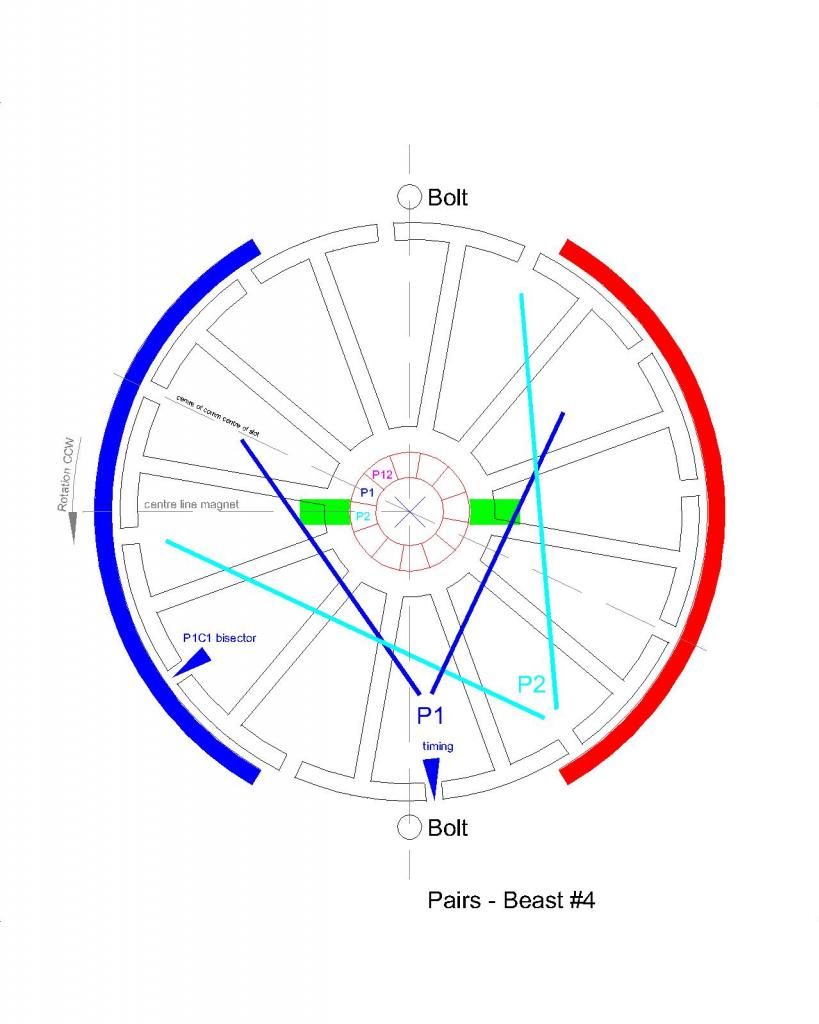
            • Beast #4 Timing - 4+4 pole Pairs

              Hi UFO

              Timing of the 4+4 pole pairs. As you can see the timing is way over in the attraction. It was slow to accelerate but got up to a good speed but the torque was pretty low.

              [IMG][/IMG]

              I'll hopefully have this wired by the weekend.

              happy hunting

              mark

              Comment


              • Not good Timing setting Mark...

                Originally posted by HuntingRoss View Post
                Hi UFO

                Timing of the 4+4 pole pairs. As you can see the timing is way over in the attraction. It was slow to accelerate but got up to a good speed but the torque was pretty low.

                [IMG][/IMG]

                I'll hopefully have this wired by the weekend.

                happy hunting

                mark
                Hello Mark,

                Yes definitively this Motor will run slow and weak (if it does run at all..., and obviously you made it run...good thing though!...)

                As your Diagram above...you are FULLY Firing P2 (fully means that a higher percentage of commutator element surface is "matching" almost the whole Motor Brush contact area, perfect alignment), and Coil # 2 from P2 (right hand side Coil) is passing the South Stator Bisector...and at this point it would be retarding rotation big time.

                I know it is entirely my fault for giving you that darn needle-pointer as being the center of both coils in the pair...WRONG...my bad...

                The Main Tip for a perfect alignment is to set P2 when it is almost leaving brush contact AND P1 is just STARTING to make contact...just like I have shown on previous Diagrams. Then make P1 Coil 1 Bisector to be almost passed North Stator Bisector by very small degrees...no less than Five (5º) Degrees though. Then make sure P2 Coil 2 (while still contacting brush) not to be even aligned with South Stator Bisector...much less passing it.

                Hope this corrections will make a difference in your builds friend.


                Regards


                Ufopolitics
                Principles for the Development of a Complete Mind: Study the science of art. Study the art of science. Develop your senses- especially learn how to see. Realize that everything connects to everything else.― Leonardo da Vinci

                Comment


                • Excellent Sam!

                  Originally posted by sampojo View Post
                  Quite Right Mark!

                  Pulsing: What UFO shows on his My Motors thread ( I urge you to study all the ~100 pages) is how to get radiant energy out of a coil by pulsing and then how to apply it to a motor's coils. But in a nutshell you may maximize RE by pulsing coils sequentially at a suitable low frequency. In multi-stator asym designs you may 1/2, 1/4,1/6 depending on the number of brush pairs/stators, the amount of input power theoretically needed to run the motor by a normal unpulsed direct feed. You can skip over the 555 board designs to focus on the monster driver John Stone V5.1 and Arduino Programmable Logic Chip designs. I need to confirm this but even my dual stator motor was running on electron fumes, hundreds of milliamps, off scale of my 20 amp ammeter, when it normally would take 1-1.5A.

                  Construction: If a conventional symmetric motor body is not machined to asymmetric specs, (matching diameter shaft, interchangeable brush mount endplates) then they must be made to spec. One easy way to achieve this is the practice of sawing off the butt end of a symmetric motor flush to the magnets and joining the bodies there, leaving two brush mount ends on either side. Of course you must find a strong connection mechanism and the bodies must be made true. In these motors, no need to dismount magnets. I arc welded the bodies together. Heating of magnets must be minimized or else they lose their magnetism. I go for bigger motors that can take things like arc welding since the heating is rather instantaneous and can be controlled by using heat sinks like a damp rag on the inside. (Soldering will actually deliver more heat to the magnets than welding since its not as fast as arc welding.) This way you have doubled the size and strength and energy output capability of the motor by using more of the old symmetric components!

                  Excellent response Sam!

                  I would like just to add that "Dual Stators" are meant (in our vocabulary) to Two Stator Motors...versus the "Quad Stat" or Four Stator / Four Brush Structures.

                  I am glad you have -finally- arrived to a smooth running System my friend!

                  I'd like to make an additional comment on the stepper motor effect I saw, I don't recall any one posting about this before, for the entire 2 years! Is the motor saying it is liking operation at specific rpms, i.e. frequencies, i.e. HARMONICS anyone???? i.e. maximum zero point energy tap points???? Hmmm One of Tesla's favorite topics as I recall!!!!


                  I am truly excited...

                  My Friend...this motors could be used as "Servo Motors" easily for Robotics applications...step by step and very accurate...remember they use coil segments fired INDIVIDUALLY and NOT ALL in SERIES like Symmetric ones...


                  Kind Regards and hope you are doing better with your Hips and this weather up North...so, stay warm!


                  Ufopolitics
                  Principles for the Development of a Complete Mind: Study the science of art. Study the art of science. Develop your senses- especially learn how to see. Realize that everything connects to everything else.― Leonardo da Vinci

                  Comment


                  • Splash of cold water

                    20 amp gauge just acting funny on low reading, read a littl e less than 1A for one channel only a little bit today and then got stuck unresponsive down near zero again. Put an inline meter to capture both feeds, was reading about 1.6A today at full power on the AMC. However my motor is only getting around 2800rpm today, not the 3400 I had yesterday. Spurious rpm reading maybe. Inline direct feed is getting about 1.8A and 3450~rpm, about the same. Playing with the frequency, seems to do best at speeds when you can see the blinking... getting varying performance out of driver boards, sometimes there is a leakage current when duty cycle is down to 0. Gone at the moment, just breaking in those IC's yuk yuk. Some stepping of rpm still seems evident, but maybe the motor needs broke in too. runs better in one direction than the other, 200 more rpm there. Just got a little excited perhaps just getting the controller circuitry to work at all! also seems I have a bad mosfet, detected at a 50ohm short condition, not completely shorted, from originals on board I shocked a while back, mishandling the power on slow start requirements.

                    all the kinks need flattening...
                    Last edited by sampojo; 12-03-2014, 01:18 AM.
                    Up, Up and Away

                    Comment


                    • Thanks, will be checking it out. Looking forward to seeing your new projects.

                      Comment


                      • Has anyone sent a NN assym motor to be tested again by IMPERIAL ? Did it fail also like the NS assym motor ?

                        Comment


                        • why ask why?

                          Comment


                          • Beast #6

                            A little later than intended but here are the figures for Beast #6.

                            0.5mm wire - 22 turn 4 pole coil in pairs. 12 pairs total.

                            5.39v PSU no load
                            5.04v @ 1.72A @ 2198 rpm.
                            3.2v out.

                            10.34v PSU no load
                            10.15v @ 2.11A @ 5208 rpm.
                            7.53v out.

                            Torque -
                            @ 5v - 125g @ 100mm @ 8.85A stall
                            @ 10v - 240g @ 100mm @ 18.42A stall

                            happy hunting

                            mark

                            Comment


                            • if you use a windmill or some other way to turn the assym motor,will it have 2 outputs?

                              Comment


                              • Hi esesenergy

                                I just drove my assy with an OEM and yes, two outputs.

                                mark

                                Comment

                                Working...
                                X