Announcement

Collapse
No announcement yet.

- 5x More Current Out Than In - Validation Of Proof Of Concept -

Collapse
X
 
  • Filter
  • Time
  • Show
Clear All
new posts

  • #31
    @ realmikel - I await a response from - ENGINEERING -

    @ GSM - I await a response from - ENGINEERING -

    @ ChrisW - I will write you a detailed response.

    @ All

    Here is something to chew over for a while until I return.
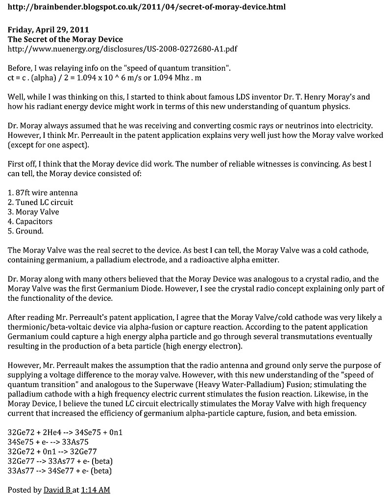


    Brain Bender: The Secret of the Moray Device

    https://dl.dropbox.com/u/33118048/Th...y%20Device.pdf

    Just incase it disappears:

    https://dl.dropbox.com/u/33118048/Br...y%20Device.mht

    Comment


    • #32
      Originally posted by kcarring View Post
      @soundiceUK

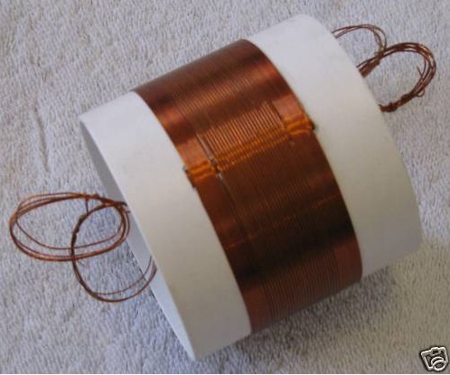
      Thanks for sharing. The photo seems to show a primary and secondary on an air core, yet the schematic shows only L1. Also, the secondary on the photo appears to have four different strands of magnet wire exiting/entering the form. Can you clarify the inductors/transformer? Thanks.
      Mystery Coil used in Validation.


      New custom wound coil for the Mystery Crystal Radio | eBay

      Comment


      • #33
        Hi everone, thanks for the good stuff Paul and Bruce, i am looking forward to this build, im behind in my experiments, but will definitely get to this one
        In the beginner's mind, there are many possibilities.
        In the expert's mind there are few.
        -Shunryu Suzuki

        Comment


        • #34
          Just a quick one for now


          Originally posted by realmikel View Post
          What is your improvement in these circuits you are sharing with this forum?


          - ENGINEERING -
          ______________

          We are obtaining useful electrical power from the planetary IONS.

          We are tuning into the 7.8 Hz planetary ion oscillations, not the electromagnetics.

          Comment


          • #35
            Marco's Dancing Magnets - YouTube
            Half of the Answer is knowing the right Question

            Comment


            • #36
              The larger the coil the lower its resonant frequency, how large of a coil would it take to get the frequency to 7.8 hertz or a harmonic thereof.
              Is this what Newman was trying to do with his huge coils.
              Im not trying to distract from your thread Soundiceuk just contemplating frequency's.
              Half of the Answer is knowing the right Question

              Comment


              • #37
                @ ChrisW

                1. Thank you for your altruism.
                Thank you for teaching me two new words.

                It made me realize that I am much more like myself when I was younger. I lost my way and now I'm back on the right road.


                2. Thank you for sticking it to the London bankers.

                I was talking to a mother at the school gates who used to work at the at a mental hospital about people who feel no empathy. She said "yes, a perfect psychopath!"

                3. Tesla referred to 500KHz as the "storm frequency." Source: Colorado Springs Notes.

                An interesting play with numbers... 500khz, 547khz, and 1.094 Mhz are harmonics of 8 - the 500 and 547 create a beat of 47khz which is also a harmonic of 8.

                547 KHz divided by 1.094 = 500 KHz EXACT storm frequency.


                4. The 7.5 to 8.0 MHz range might also be of interest. See Deyo's work.

                Personally I haven't studied Deyo's work. Sorry Chris but is that supposed to be hz or Mhz?

                5. The larger the wire diameter of the antenna, the greater the voltage impressed upon it. Source: ARRL Antenna Book.

                Larger antenna surface area means it is easier to harvest IONS.

                6. What I'm dying to see is the full range of frequencies between 5Hz and 8 MHz on a spectrum analyzer. That way we'd know where the most energy lies.

                I think I have a photo buried in my emails. I'll try to find it.

                7. Multiple stages could be implemented in this device to step down the frequency in each stage at the sub-harmonics to increase the voltage and current.

                The high powered design is making progress day by day. We look forward to delivering it to you one day if we can get enough support.

                8. I'm not sure that adding the two 1.5V batteries is the way to go. I think adding a couple of 5V super caps (in the quarter to half farad range) might be a better approach.

                We have spoke of using capacitors. I'm sure there are many ways to tweak the Proof of Concept circuit. Your imagination is your limit. If someone can suggest an easier proof of concept then we would welcome it. I think the ultimate goal is definately to make it far more A-Z. Slowly we are making progress.

                9. I agree with the idea of adding a pair of voltmeters to the build. Seeing the voltage AND the current would provide definitive proof of additional energy in the circuit.

                I understand there are a number of members replicating. So hopefully we will have a better write up soon. The engineer in question is working on the finer details of the higher power design. So it is best not to disturb him. I will add some labels to the photo as soon as I can.

                10. I would very much like to see the oscillator's energy coupled into the circuit via the primary. Ideally, the primary and secondary would be tuned to the same resonant frequency. A bit more effort required, but essential for optimum performance.

                I'm still waiting to hear back from - ENGINEERING - at this point.

                Keep up the great work... cheers, mate!

                MY PLEASURE!!!!

                Comment


                • #38
                  @ Dave45 - I love that video, I think there is another very similar one too on Youtube. The theory of this technology is most important.

                  - ENGINEERING -

                  What the video confirms is that we can obtain energy from our Radiant Energy Power Receiver if it is tuned to oscillate at 7.8 Hz.
                  Last edited by soundiceuk; 07-24-2012, 12:21 AM. Reason: .

                  Comment


                  • #39
                    Originally posted by mr.clean View Post
                    Hi everone, thanks for the good stuff Paul and Bruce, i am looking forward to this build, im behind in my experiments, but will definitely get to this one
                    Many thanks for your support through all of this Mr Clean

                    I think we all respect your warrior spirit!!!!!

                    Comment


                    • #40
                      Originally posted by Dave45 View Post
                      The larger the coil the lower its resonant frequency, how large of a coil would it take to get the frequency to 7.8 hertz or a harmonic thereof.
                      Is this what Newman was trying to do with his huge coils.
                      Im not trying to distract from your thread Soundiceuk just contemplating frequency's.
                      I will check with - ENGINEERING - for you.

                      Comment


                      • #41
                        @ realmikel & GSM

                        Facts that we believe you should know

                        1. Radio communication utilizes electromagnetic oscillations (electromagnetic radiation or which can be alternatively called electromagnetic radiant energy); in what we know as the radio spectrum.

                        2. ION power conversion utilizes electrostatic oscillations (electrostatic radiation or which can be alternatively called electrostatic radiant energy); what should be termed the planetary energy spectrum.

                        3. With these facts in mind it should be easy to envision how we can extract useful electrical power from the planetary ions.

                        4. Nikola Tesla and T. H. Moray both were correct in assuming that we cannot obtain electrical power from a purely "static" charge.

                        5. However, we can obtain electrical current from a moving, oscillating, or a vibrating ionized particle. If a highly charged particle sits on the surface of a neutrally charged solid surface it is a static charge. If however; a highly charged particle that is free to move on the surface of a liquid or in a gaseous atmosphere it is not static, it is a moving charge. It is a fact that a charge in motion can and does induce a moving charge of current in an electrical conductor that it approaches, or if it is moving away from it.

                        Nikola Tesla said:

                        "If ever we can ascertain at what period the earth's charge, when disturbed, oscillates with respect to an oppositely electrified system or known circuit, we shall know a fact possibly of the greatest importance to the welfare of the human race. "

                        "If static, our hopes are in vain; if kinetic - and this we know it is, for certain - then it is a mere question of time when men will succeed in attaching their machinery to the very wheelwork of Nature."

                        "When the great truth, accidentally revealed and experimentally confirmed, is fully recognized, that this planet, with all its appalling immensity, is to electric currents virtually no more than a small metal ball and that by virtue of this fact many possibilities, each baffling imagination and of incalculable consequence, are rendered absolutely sure of accomplishment;"

                        Bruce A. Perreault
                        July 23rd, 2012

                        Comment


                        • #42
                          Originally posted by soundiceuk View Post
                          @ realmikel & GSM

                          Facts that we believe you should know

                          3. With these facts in mind it should be easy to envision how we can extract useful electrical power from the planetary ions.

                          5. However, we can obtain electrical current from a moving, oscillating, or a vibrating ionized particle. If a highly charged particle sits on the surface of a neutrally charged solid surface it is a static charge. If however; a highly charged particle that is free to move on the surface of a liquid or in a gaseous atmosphere it is not static, it is a moving charge. It is a fact that a charge in motion can and does induce a moving charge of current in an electrical conductor that it approaches, or if it is moving away from it.
                          #3 This sales talk implies if it is not easily understood then the problem is with the reader not the explanation. I understand that you can quote many knowledgable individuals, I am asking how what you quote brings you to the conclusion that you have improved the device directly word for word. Don't worry about being too complicated I actually understand some theory. For example hetrodyning, frequency a with frequency b will produce on the other side of the mixer a , b, a+b, a-b. Now if your getting extra energy which frequency is providing it and how much energy is provided above the 60% loss of the energy used by the mixer?

                          #5 Wonderful explanation about electrical theory. Absolutely fills up the page and sounds important. Does not explain the first thing about your device or circuit or its improvement over any other circuit so it is understood again as salesmanship of unrelated "facts" copied from other peoples work.

                          The disadvantage of quoting say "Tesla" is that he invented polyphase motors at the end of the 19th century and today almost every polyphase motor looks exactly the same as the one Tesla built himself. That means a lot of people for 100 years have followed or quoted Tesla yet few have the ability to improve on his work. I am still waiting for your explanation on how your circuits are an improvement over Tesla's used in his radio equipment at the 1900 worlds fair many years before marconi's patents

                          Comment


                          • #43
                            @ realmikel

                            Sorry it hasn't answered your questions but at least for now it has defined them and the detail of answers you seek.

                            I will endevour to seek what you require.

                            Cheers,

                            Paul =)

                            Comment


                            • #44
                              Originally posted by soundiceuk View Post
                              Hopefully we can close the gap in our learning soon and move forward as one with this technology.

                              - PRIVATE ENGINEER -

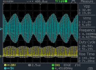
                              I thought these might be interesting to any one working on the beat frequencies.

                              This first one is when it locked.


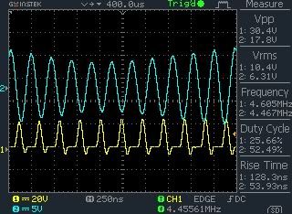
                              The yellow is the driven oscillator and the blue is not powered, simply a slave.

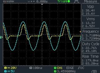
                              Below shows the two oscillations when there is no beat lock, both latch on to the same phase.


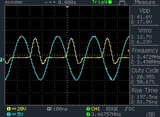
                              You can tune one oscillator or the other to shift the phases so when one is high the other is low. This is when you start shaking the environment. Below shows the beginning of a phase shift...


                              The next one shows the first one expanded....


                              I find this interesting because when you look at the center of the beat you can see the phase shift but also that the slave oscillator is leading the primary oscillator peaks on ring down, they line up in the center then trail slightly during ring up.

                              I may be interpreting this wrong but in my mind the ring down side is giving energy to the driver and on ring up the driver is giving energy to the slave.

                              Also interesting is both the 1st picture and the last are from the same test oscillator, the difference between the beats is 79000 hz in the first and the second is 138000 hz the first is a harmonic of 7.9 the second 8. With no real way of making tiny precise movements I'd say I came pretty close, this seemed to be the only spot between the pair that I could get a beat lock.
                              Excuse me,
                              but we have been told of only ONE energising oscillator being used, but the text here states two !?

                              Yes a beat is generated between different source frequencies.
                              This is claimed to happen with V2.5 and V2.6 with only a single oscillator ?
                              The beat is claimed to come from an 'Earth' based resonance, but does it ?
                              Or does the beat arise between longitudinal antenna resonance and the tuned inductor resonance ?

                              Also did the original V2.5 change ?
                              I read of a tiny Texas IC being used, but not now. I also think the coil winding turns changed slightly.

                              I have the TPS61254 IC now on the evaluation board (not cheap) and I see I will need to remove the output capacitors.
                              Waiting for 2 each of moving coil amp and volt meters.
                              Have wire for the coil now too.
                              Antenna ? Will do what I can.
                              I intend to breadboard first and get running, but I'm thinking of trying a 20m coil of 3/8" copper tubing spaced over wooden supports.

                              Cheers ....... Graham.

                              Comment


                              • #45
                                Originally posted by realmikel View Post
                                #3 This sales talk implies if it is not easily understood then the problem is with the reader not the explanation.
                                I can see your point. The purpose of this thread is to open a discussion up and educate everyone reading at the same time. I haven't got all the answers, but I can seek them.

                                I want to provide all the information you seek so that the questions will help formulate a detailed FAQ sheet that even Joe Bloggs can understand.

                                I'm certainly not trying to avoid your questions or be clever. I'm working with the best information I have in front of me at the time.

                                I don't speak to the team on the end of the phone or skype. This is all done via email.

                                Originally posted by realmikel View Post
                                I understand that you can quote many knowledgable individuals, I am asking how what you quote brings you to the conclusion that you have improved the device directly word for word.
                                Is this interpretation correct?

                                You would like me to write which modifications need to be made to improve the devices output and show how it was measured to reach that conclusion?


                                Originally posted by realmikel View Post
                                Now if your getting extra energy which frequency is providing it and how much energy is provided above the 60% loss of the energy used by the mixer?
                                I am going to partially attempt this one with my basic understanding.

                                If the oscillator is running at 3.5mhz, then the tank circuit must be tuned to roughly 7.8hz less.


                                Would it be fair to say these are the other unanswered questions.

                                If not please edit.

                                1. Is the frequency providing extra energy? If not, what is.

                                2. How much energy is provided above the 60% loss of the energy used by the mixer?

                                3. Please explain about the device or circuit or its improvement over any other circuit Tesla used in his radio equipment at the 1900 worlds fair many years before marconi's patents.

                                Cheers,

                                Paul

                                Comment

                                Working...
                                X