Announcement

Collapse
No announcement yet.

- 5x More Current Out Than In - Validation Of Proof Of Concept -

Collapse
X
 
  • Filter
  • Time
  • Show
Clear All
new posts

  • #61
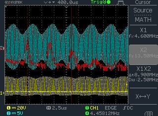
    The 'engineer(s?)' responding, and the original file uploaded both relate to tuning a slightly lower frequency in order to peak up on a generated beat frequency.

    If this beat were Schumann Resonance related, then it would not matter whether the tuning were higher or lower than the inducing fundamental !!!!!
    This is a very interesting point.
    The very first post that started this thread show a picture of a working model. I assume that in this case the LC circuit is tuned below the osc. frequency as in the instructions.
    I would very much like to see the results if you take this circuit and tune the LC equally far above the osc. freq. as it is now below.
    Just to make sure I get my point across: I am not interested in a theoretical reply at this point, I would like to see the result.
    Comment


    • #62
      Originally posted by ChrisW View Post
      6. What I'm dying to see is the full range of frequencies between 5Hz and 8 MHz on a spectrum analyzer. That way we'd know where the most energy lies.
      I couldn't find the picture in my very busy inbox. So I asked for it again.

      Here was the response.

      - PRIVATE ENGINEER -

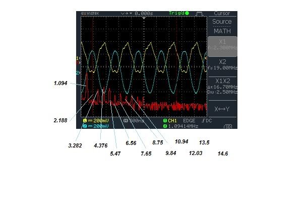
      I have a scope with math function which includes FFT and makes for a "dirty" spectrum analyzer. A "poor boys" spectrum analyzer. I don't remember which one it was that I sent but I'll send one of the more resent ones playing with beat frequencies.


      This is one that I noticed one of the peaks was in the range that Dr. Stiffler was working with ( 13.5 Mhz - about center ). Each of the peaks in this one represent a wide band of frequencies that are being developed.


      Thinking about it, it might have been this one producing 1.094 harmonics along the spectrum...

      ___________________________________

      When I uploaded these shots to my photobucket account I found the one I was looking for but it offers less detail.

      Comment


      • #63
        Hi everyone

        The 2nd Edition is constantly evolving based on your feedback. This is how we got from the 1st to the 2nd Edition with a very small team.

        The interest in EARTH ION ENERGY is growing and so is the constructive feedback.

        Thank you all very much for contributing your time, knowledge and finances.

        We are already producing v0.13.


        We think you will be glad to hear that we have decided to get rid of the idea of having a manual where you have to pay more, for more information.

        Instead, everyone gets the same information and the updates are subscription based.

        We wish we could be completely self funded and provide a totally free open source system, but unfortunately at this moment in time it is not possible.

        Sharing the technology with a cycle of:

        publication > education > feedback > new version

        will allow us to move forward quickly and hopefully prevent the technology from ever being buried, whilst bringing a high wattage design into the public arena.

        As far as I'm aware no one has ever attempted this model for global release.

        There is a first time for everything!!!


        Here are the subscription figures.

        One off = $3.

        Bronze = $5 for 1 month of updates.

        Silver = $12 for 3 months of updates.

        Gold = $18 for 6 months of updates.

        Platinum = $24 for 12 months of updates.


        Early bird purchasers prior to the release of this statement will be given a Platinum subscription for your early support.

        This is also a way of contributing to the research and development for existing 2nd Edition owners, should they so wish.

        Please keep the feedback coming.


        The current top four on my to do list:

        1. I have quite a few alterations to make and about 100 v0.13 BETA's to send out.

        2. Tackle the remaining questions from this thread.

        3. Draw an accurate schematic of the validation of proof of concept and label the photo.

        4. Fix the DNS problem between Earth ION Energy and EARTH ION ENERGY - © COPYRIGHT 2012 - ALL RIGHTS RESERVED

        Comment


        • #64
          Thoughts and questions

          Hi all,
          Just a lil preamble here. I have a background in radio communications test and development and have been studying Tesla tech for a few years now.
          I understand conceptually on some level what the proof of concept ccts are attempting to do and have ordered a few components to replicate in the near future.

          From my understanding you want to share some information via a subscription method which appears to be a reasonable concept. I also understand that you have concerns regarding liability because of the very nature of the project (lots of energy) and potential harm that can do.
          So I am wondering how that will work in the real world when it comes to sharing updates over time, releasing information for higher energy prototypes, and sharing the technology far and wide so that it does not get suppressed, again?

          Additionally, I note that in some of the earlier versions there are already sections of the ccts that can be lethal to those skilled and experienced with high voltage/currents, as well as with laymen alike. I am specifically thinking of the 12V to 3000V AC step up transformer.
          One thought that has come to mind is, from a safety perspective, perhaps you may consider introducing some report submission system so that information for higher energy systems can be shared with those who have a grasp of the fundamentals so to speak.

          Questions:
          I have seen 2 official posts regarding the length of antenna:
          One indicates that the gauge is not so important but the length is more critical, including up to the point of termination to the device.

          “You need a 65' (preferably bare) copper wire of sufficient gauge for support between two insulators. The gauge is not so much a deterministic factor as the length of antenna. Make sure to include the lead wire length from your circuit connection, to top antenna, in your length calculations. The gauge can be anywhere between 14 to 20 AWG. You want a well soldered connections and keep away from any power lines in the area...as well as stay away from any metal object!”

          The other post from your engineer indicated that having a long antenna is not important.

          “You are missing the point. When you heterodyne with the atmospheric ions...you create a "group velocity" that travels at 7.8hz that just happens to tune into the VLF earth oscillating ions. You do not need a LONG antenna to do this as most would think. This is only one of the methods of gain that T. H. Moray utilized.”


          Does that mean there is a resonant or matching function that is required from the antenna?

          Are there benefits from have an antenna that is strung out or mounted more localized, i.e. zigzagged or coiled?

          Does the weight/mass of the copper antenna have any significant bearing?

          One would assume that one of the objectives here is for the antenna to experience as much Ion movement at Earth’s resonant frequencies a possible, in order to facilitate the Ionic energy transfer at 3.5MHz to 7.8Hz?

          How are you able to determine what part of the energy excitation is from manmade noise or naturally occurring noise?

          Thnx
          Kris
          Last edited by Neo1; 07-28-2012, 03:55 AM. Reason: Spelling

          Comment


          • #65
            Originally posted by Ernst View Post
            This is a very interesting point.
            The very first post that started this thread show a picture of a working model. I assume that in this case the LC circuit is tuned below the osc. frequency as in the instructions.
            I would very much like to see the results if you take this circuit and tune the LC equally far above the osc. freq. as it is now below.
            Just to make sure I get my point across: I am not interested in a theoretical reply at this point, I would like to see the result.
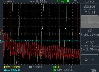
            Well - still no reply here, and I suggest there cannot be either.

            Also if we ignore the fundamentals upon which theory is based then we are unwisely attempting to travel blindly along an unknown path !

            Might I suggest consideration of the following:-

            Electrostatic charges are potential energy, and as stated "static".

            I suggest that what is happening here is the taking of energy from an ionodynamic wave (kinetic motion), this generated by an electrical transient (electron based transient from the circuit, and NOT previously there, nor distant noise of any kind, nor Schumann Earth Resonance related!)

            The primary energy is electron charge induced (potential energy) with respect to earth, but not electromagnetically radiating because there is minimal linear alignment of the electron orbits as is essential to generate a coherently radiating photon stream.

            The received energy for this circuit is via ion recombination, which having mass (gaseous) has a (sound wave like) kinetic wave energy which may be 'tuned' by the receiving apparatus. Yes a group wave velocity, and this causing transducibly resonant motion.

            This is a local event within the ambient, and it is not powered by any interference or other ionodynamic waves having different frequencies and from other locations. Just as sound is a local disturbance of the ambient then so too (and most unlike electromagnetic radiation) are the ionic wave disturbances. Ionic noise does not - cannot - travel far (not even as far as sound) and not in the same way that electromagnetically radiated photons do, because there are natural molecular charge recombination (neutralising) events throughout the atmosphere.

            These are ion-electron relationships within the local environment, in the ambient atmosphere above local ground, and this overall air-ion-ground-electron relationship ought not be overlooked.

            And why should there be an electron-ion gain ?
            Because the energy to electrostatically discharge via near massless electrons is miniscule compared to the equal electron-ion charge based kinetic wave motion based disturbance of relatively massive ionised gas molecules.

            If this were a grand scale event related to the Schumann Earth Resonance there would be beats above as well as below the receiver fundamental.

            But how could there be due to ion neutralisations throughout the atmosphere ?

            This is related to the kinetic energisation of air molecules, and the charge disturbance momentum induced due to relatively large air molecule ions moving to neutralise an invisibly small electron charge generated by the equipment.

            I further suggest that the beat frequency will be different for every constructor, and also be different at every different location. Also that the beat will change with air pressure variations and humidity = weather.
            Thus this will not be a viable stand alone source of energy unless the air ions are contained within their own stable environment, as in a special room, or a special 'antenna' (resonant coil) is blown with tightly controlled air characteristcs.

            Cheers ......... Graham
            Last edited by GSM; 07-28-2012, 09:16 AM. Reason: spelling

            Comment


            • #66
              @ All

              Please bear with me answering all your questions. I will get through them.


              @ GSM

              Here is the answer to your main question.

              - PRIVATE ENGINEER -

              I've worked with both higher and lower and one wave will travel one direction of the original the other with travel opposite.


              @ Neo1

              I echo your thoughts regarding subscriptions.

              Are there any suggestions on how the liability issue could be overcome?
              Last edited by soundiceuk; 07-28-2012, 12:34 PM.

              Comment


              • #67
                This is a very interesting point.
                The very first post that started this thread show a picture of a working model. I assume that in this case the LC circuit is tuned below the osc. frequency as in the instructions.
                I would very much like to see the results if you take this circuit and tune the LC equally far above the osc. freq. as it is now below.
                Just to make sure I get my point across: I am not interested in a theoretical reply at this point, I would like to see the result.
                Well - still no reply here, and I suggest there cannot be either.
                If you think there can not be a reply, you misinterpreted my question. There can be and now there is:
                I've worked with both higher and lower and one wave will travel one direction of the original the other with travel opposite.
                Only I can not translate this answer to "yes, in that case you also receive energy" or "no, you only get energy if you tune the LC lower". And that was actually what I was hoping to hear.

                I strongly believe that we must not start creating new theories until the existing theories fail. That is also how modern science went off the right track and got lost in the quantum jungle. They should have stayed with ether...

                Comment


                • #68
                  Originally posted by Ernst View Post
                  I strongly believe that we must not start creating new theories until the existing theories fail. That is also how modern science went off the right track and got lost in the quantum jungle. They should have stayed with ether...
                  Good point, but some things already stated cannot be possible !

                  You say aether, I sat 'i'ther, but i'm not calling anything off - I'm already constructing; though strapped for time, and I don't even have a workbench either.

                  .......... back to work ...........

                  Comment


                  • #69
                    waiver, releases re liability

                    Contact an intelligent ambulance chaser, sorry, typo, attorney and bring up the above terms? You are released of liabilities and the reader waives any claims against you. Again, pass it by your local expert. Oh, and get the opinion of his/her in writing? Just some thoughts. Best wishes!

                    Comment


                    • #70
                      Hi zapzap.

                      No one needs an ambulance yet; I've only got wallet-ache !

                      Okay.
                      I just finished constructing the original V2.5 (Bruce Perreault?) proof of concept Radiant Energy receiver circuit, and it won't run.

                      Now I have published circuits myself, and not only were they all fully tested and fully working, but I still stand over them because my word is my bond; this being the way I was brought up, and something that I will not change - no matter what.

                      So did I think it would work ? I did not know because I do not know the exact nature of the Texas Instruments TPS61254 switching PSU IC sensing and switching capabilities. I did decide to make a test constuction however, because so much more than publication honesty could be at stake here.

                      The original published article stated that just 80mA of circa 4.5V input consumption produced more than 5x this at output.

                      Well the tiny IC runs as specified with 10uF of output waveform smoothing, but it will not run without that capacitor because it draws higher current, and it most certainly does not want to run into the short circuit of an RF coil.

                      So I am obliged to seek further information from 'Engineering' and ask what other components were used with that Texas IC in order to make it run as the 3.5MHz 'BFO' drawn on the original text ?

                      Of course I am wondering too why that V2.5 circuit was changed after I started to order in my parts.

                      Also, in investigating the non-functionality by listening for the oscillating 3.5MHz regulation control using a SW radio, I did not hear the IC, but I did note some quite powerful signals in the 3.5MHz range.

                      There are many "defense/military" transmitters around 3.5MHz these days, so here I ask whether this circuit has been taken to and demonstrated at other locations (as did Moray, Hendershott etc.) or does 'Engineering' just happen to be make their measurement close to one of these "military" transmitters ?

                      Looking forwards to a reply.
                      Last edited by GSM; 07-29-2012, 12:39 PM.

                      Comment


                      • #71
                        Don made some comment here

                        GSM
                        Have a read [a quick read]

                        tate ambient power module

                        Thx
                        Chet
                        Last edited by RAMSET; 07-29-2012, 01:34 PM.
                        If you want to Change the world
                        BE that change !!

                        Comment


                        • #72
                          Hi GSM,

                          In studying the schematic given in v2.5 (included in the very first post of page 1) and reading the text on (I quote) "The radiant energy receiver proof of concept schematic works by heterodyning with the ambient electrostatic planetary noise. This is accomplished by tuning the L1/C1 oscillating tank to a slightly lower frequency than the OSC. Extremely Low Frequencies are generated. These lower frequency beats are more efficiently converted into useful electrical direct current through the crystal detectors D1 and D2."
                          I would like to notice the followings:
                          Across which component(s) can the generated very low frequency beats develop so that the diodes (D1 and D2) would be able to rectify them?
                          Or putting this otherwise, let's examine the frequency-dependent impedance at the antenna connection point with respect to the ground G1, there is the oscillator output point's impedance and there is the 3.5MHz L1C1 tank circuit impedance and there is the lamp load with the series diodes. Out of these three possibilities, the smallest impedance seems to be the L1C1 tank circuit for the heterodyned low frequency components because a parallel LC circuit behaves as a short circuit, a shunt, at the much lower frequencies than the 3-4MHz band.
                          So from that schematic I cannot see any possibility for the 21W lamp to bright up as per the original text suggests.

                          I understand there have been modifications and further version(s) since v2.5 have been issued.

                          This is an observation from my part, I do not wish to 'declare' anything in advance, for I did not build v2.5 schematic. However you did and I tried to understand 'circuitwise' what is this circuit about at all and how it works.

                          rgds, Gyula

                          Comment


                          • #73
                            Originally posted by GSM View Post
                            Found it impossible to desolder the output capacitor from the TPS61254 evaluation board.

                            Hope I did not damage the IC with heat. Had to nip the capacitor away with fine cutters then tidy up the solder with the point of a craft knife.

                            - ENGINEERING -

                            We're terribly sorry to hear of your troubles.

                            The problem that we see is that the TPS61254 that you are using isn't providing the required pulse-train.

                            You reported that you cannot hear the IC.

                            If there is no oscillator signal from the IC, then this is why the circuit isn't functioning the way that it is designed to function.

                            The sticking point here is that the circuit wasn't tested with the TPS61254 IC being a signal source for the RF coil.

                            Bruce carried out his orginal experiments with a TPS61254 oscillator that he lifted from an old computer motherboard back in
                            2003. He no longer has this oscillator but an RF signal will serve the same purpose, it's just a lot more bulky to use.


                            GSM - For the small part you have been involved, I think you have been a great help in this journey.

                            v2.6 changed from TPS61254 to 3.5Mhz - 4Mhz oscillator because the feedback we had received was that the chip was too difficult to work with.

                            There are still many bugs in the service we are trying to provide. It isn't perfect, but with feedback from more people like you it can be.

                            I feel somewhat oblidged to compensate you for the experience, in the hope to move things forward positively.

                            How much was the eval board?

                            Comment


                            • #74
                              Originally posted by RAMSET View Post
                              GSM
                              Have a read [a quick read]

                              tate ambient power module

                              Thx
                              Chet
                              Thank you for your reply Chet.

                              That circuit is capacitively coupled and a passive voltage multiplier, therefore not capable of atmospheric-ion to ground-electron conduction.

                              Cheers ......... Graham.

                              Comment


                              • #75
                                Originally posted by soundiceuk View Post
                                - ENGINEERING -

                                We're terribly sorry to hear of your troubles.

                                The problem that we see is that the TPS61254 that you are using isn't providing the required pulse-train.

                                You reported that you cannot hear the IC.

                                If there is no oscillator signal from the IC, then this is why the circuit isn't functioning the way that it is designed to function.

                                The sticking point here is that the circuit wasn't tested with the TPS61254 IC being a signal source for the RF coil.

                                Bruce carried out his orginal experiments with a TPS61254 oscillator that he lifted from an old computer motherboard back in
                                2003. He no longer has this oscillator but an RF signal will serve the same purpose, it's just a lot more bulky to use.


                                GSM - For the small part you have been involved, I think you have been a great help in this journey.

                                v2.6 changed from TPS61254 to 3.5Mhz - 4Mhz oscillator because the feedback we had received was that the chip was too difficult to work with.

                                There are still many bugs in the service we are trying to provide. It isn't perfect, but with feedback from more people like you it can be.

                                I feel somewhat oblidged to compensate you for the experience, in the hope to move things forward positively.

                                How much was the eval board?
                                Hi Paul.

                                The IC is working okay - as long as it is fitted with a 10uF output capacitor as originally fitted and as intended by Texas Instruments, whereupon of course there is no 3.5MHz output to the V2.5 coil because the 10uF is low ESR damping and in parallel with the coil.

                                The Texas TPS61254 was only designed last year for use in miniature radios, portable audio etc. where EMI is most undesirable.

                                So Bruce likely used something like an encapsulated temperature compensated crystal reference clock oscillator module from a computer pcb ? Something like this
                                http://www.rapidonline.com/Electroni...llator-90-0960
                                though generally these are not of high power.

                                So where does this leave constructors wishing to replicate V2.5 and V2.6 ?

                                Cheers ......... Graham.

                                Comment

                                Working...
                                X