Announcement

Collapse
No announcement yet.

- 5x More Current Out Than In - Validation Of Proof Of Concept -

Collapse
X
 
  • Filter
  • Time
  • Show
Clear All
new posts

  • "Think slow; act fast." Buster Keaton: An entertaing fool or a very clever guy?
    The answer depends upon viewpoint.

    So I have been thinking more about V1.04 - and - "viewpoint".

    The entire D1 to D4 capacitor isolated sub-assembly also has a degree of spatial coupling.
    Otherwise only one series equivalent capacitor would work - was this tried ?

    Are the LEDs beside the transistor such that their conduction levels are being capacitively modified, and thus the ammeter readings NOT as valid as appears ?

    What about all of the S-dec strip intercapacitance reactivities ?
    I do NOT use solderless prototyping board for this very reason and would either make a birds nest construction, or use tiny solder pins in dry board, or use trackless perforated board for circuit experiments, because a few pF in base-collector and tuned circuit arrangements within S-dec can render findings unfathomable.

    This means the I and other readers here could construct that same circuit exactly as per the circuit diagram, and would likely fail to get it running as per the photograph !

    Then there is the "Earth Ground" viewpoint illustrated on the circuit diagram, which of course is not "Earth Ground" because there is series impedance in the connection between the circuit 'Ground' and the 'Earth' termination.

    Sadly there is too much information missing here.

    That V1.04 is a circuit which must be left 'as-is' until it has been re-constructed in a way which can be properly analysed and replicated, for so little has been clarified here, and the possible maximum of 60mW 'Free Energy' is likely to prove 'imaginary' via a spatially coupled, and thus phase shifted 'viewpoint'.

    There has also been a claim for higher energy output having been witnessed by the Energy Team, yet such a statement could either represent a donkey-carrot hoax scenario having motives known only to the writers, or, it might be true, and yet if it is true, such a statement is completely meaningless without validation.

    I have too many doubts about V1.04 to construct it, so why do the 'engineers' persist in keeping secrect details about their more powerful design, when they claim to have the future of humanity at heart ?
    Last edited by GSM; 08-01-2012, 11:07 AM.

    Comment


    • Originally posted by soundiceuk View Post
      Bruce just said:

      "Excellent concept, artificial radiation LeBon style! "
      LeBon - Moray - Perreault ?

      The secret is - to give your ideas away and let others run with them
      so that no individual Patentee or Commercial developer gets taxed or iced !
      Richness is of the soul, not the bank account.
      Last edited by GSM; 08-01-2012, 01:17 PM.

      Comment


      • Antenna

        @soundiceuk,

        Try an aluminium street light pole as an antenna for your circuit. These kind of grounded light poles could supply their own power without a windmill on top.
        Last edited by Allen Burgess; 08-01-2012, 04:10 PM.

        Comment


        • Originally posted by GSM View Post
          There is a Yahoo Group directly related to this.

          Yahoo! Groups

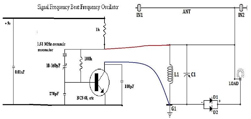
          This is a post today from a member stating that the replacement oscillator circuit provided by Bruce yesterday, is stopped by connection into V2.5
          I received this email yesterday with the following:


          Hello Paul I just wanted to note that this schematic works. Not much adjustment though, so it required changing the adjustable cap to one that covers up to 10-300pf.

          I also have adjustable caps in other two locations of 10-160pf. The one going across collector to emmiter had no effect on mine and I removed it with no effects.

          Stil not confirmed charging my antenna. It has been pulled down by a papaya tree and I need to use heaver gauge wire.


          Originally posted by GSM View Post
          I have too many doubts about V1.04 to construct it, so why do the 'engineers' persist in keeping secrect details about their more powerful design, when they claim to have the future of humanity at heart ?
          Hopefully the comparison circuit (which will be ready by tomorrow night) or one of the oscillators that have been posted in the thread will spur you on Graham.

          Folks keep telling me to stop trying to save the world. For some reason that is unknown to me, I just don't listen. I strongly believe that those who think they can change the world, will!

          I'm certainly not a puppet and no one is pulling my strings.

          Companies have a tree structure, like McDonalds.

          Earth ION Energy seems to have developed a hub / spoke structure. I seem to be the spindle.

          No one is in charge of anyone, just a feedback loop.

          My current thoughts are that the concept needs to be grasped and proven with more validations. When I know exactly which direction to send folks in, I will.

          It is certainly not my intention to give out misinformation.

          I personally would like to be completely open about everything. However, I believe this will send a horde of newbies off on a journey that could seriously harm or kill someone.

          Your recent posts go pretty much over my head. Although I get the gist.

          I'll see what I can offer next to move forward.

          Zilano carrot/donkey is a little harsh considering the effort that has gone into this.

          Comment


          • Further thoughts regarding V1.04.

            Is this circuit genuinely OU ?
            If yes it should be able to power itself.

            Connect a capacitor in parallel with the battery, say another one like the 3,300uF connected to D1 and D2.
            Insert a switch in series with the battery.
            Insert a 4k7 resistor in series with the LEDs.
            Now connect high quality 10mH chokes between the two 3,300uF capacitors; + to + and - to -.
            Tune up the circuit; switch out the battery; LEDs stay illuminated ?

            Cheers .......... Graham.

            PS. Has anyone ever had success replicating the ION Energy circuits ?

            PPS.
            That crystal oscillator circuit you have just uploaded likely has a maximum output circa 4 milliwatts.
            It might illuminate a LED, but NOT a filament lamp.
            Last edited by GSM; 08-01-2012, 04:23 PM.

            Comment


            • It is all about ionic discharge which is the cause of "radio static noise." This is what we are tuning into, not the electromagnetic radio signals which are too weak to obtain any useful electrical power from because they are too weak once they arrive at our antennas.

              The circuits haven't been out that long. Based on current feedback it appears that many folks are either broke and/or haven't got a space for a good earth and antenna.

              One of the talented electronics wizards who made the validation circuit was invited into the engineering team that consists of a number of and men who have Prof. or Dr. before their name. Not that that fact is important, I just thought you may find it interesting.

              Version 2.6 was also validated by him using the same keche (spelling) oscillator as in the photo.

              You are not the only one who baffles me regularly Graham. This is a very steep learning curve for me.

              As I am a fly on the wall in amongst all the emails, I quite regularly have my mind challenged beyond its current limits.

              Comment


              • PPS.
                That crystal oscillator circuit you have just uploaded likely has a maximum output circa 4 milliwatts.
                It might illuminate a LED, but NOT a filament lamp.[/QUOTE]

                You are very correct, running this circuit with 12v dc runs at around .006 amp on my setup. I dont know yet if there is any output for my ant. is down till I repair it this weekend. Time will tell then I will move on to the next circuit. Randy

                Comment


                • Further thoughts regarding the V1.04

                  Originally posted by GSM View Post
                  Further thoughts regarding V1.04.

                  Is this circuit genuinely OU ?
                  If yes it should be able to power itself.

                  Connect a capacitor in parallel with the battery, say another one like the 3,300uF connected to D1 and D2.
                  Insert a switch in series with the battery.
                  Insert a 4k7 resistor in series with the LEDs.
                  Now connect high quality 10mH chokes between the two 3,300uF capacitors; + to + and - to -.
                  Tune up the circuit; switch out the battery; LEDs stay illuminated ?

                  Cheers .......... Graham.

                  PS. Has anyone ever had success replicating the ION Energy circuits ?

                  PPS.
                  That crystal oscillator circuit you have just uploaded likely has a maximum output circa 4 milliwatts.
                  It might illuminate a LED, but NOT a filament lamp.

                  Hi Graham,

                  Thanx again for those inputs on the above circuit.

                  Do you think that with the changes that you recommended above, that this may indeed have the posability of it working to a certain extent?

                  If so, would you be trying it out?

                  Then, I may have a go at it too.

                  Just curious.

                  Cheers, --Parav(Paul)

                  Comment


                  • Originally posted by Parav View Post
                    Hi Graham,

                    Thanx again for those inputs on the above circuit.

                    Do you think that with the changes that you recommended above, that this may indeed have the posability of it working to a certain extent?

                    If so, would you be trying it out?

                    Then, I may have a go at it too.

                    Just curious.

                    Cheers, --Parav(Paul)
                    Hi Paul.

                    Folks need to consider where supposedly free energy might come from, and most certainly it won't come from an oscillator merely oscillating electrons or a magnetic field or a voltage field.

                    So where is the energy supposed to come from in V1.04 when there are no ion-electron exchanges nor sources ?

                    The real proof of OU would be a circuit perpetually powering itself, and if my suggestions were implemented on the alleged validation shown in the V1.04 photograph (whoever owns that), then the results would be definitive.

                    No I will not be replicating for two reasons; first there would need to be at least one Watt of 'free energy' away from all transmitters, and second because there is no source of additional energy.

                    Cheers ............ Graham.

                    Comment


                    • OK

                      Originally posted by GSM View Post
                      Hi Paul.

                      Folks need to consider where supposedly free energy might come from, and most certainly it won't come from an oscillator merely oscillating electrons or a magnetic field or a voltage field.

                      So where is the energy supposed to come from in V1.04 when there are no ion-electron exchanges nor sources ?

                      The real proof of OU would be a circuit perpetually powering itself, and if my suggestions were implemented on the alleged validation shown in the V1.04 photograph (whoever owns that), then the results would be definitive.

                      No I will not be replicating for two reasons; first there would need to be at least one Watt of 'free energy' away from all transmitters, and second because there is no source of additional energy.

                      Cheers ............ Graham.
                      I think understand what your saying.

                      We'll just have to keep plodding on then.

                      Thanx Again.

                      Parav(Paul)

                      Comment


                      • Originally posted by soundiceuk View Post
                        It is all about ionic discharge which is the cause of "radio static noise." This is what we are tuning into, not the electromagnetic radio signals which are too weak to obtain any useful electrical power from because they are too weak once they arrive at our antennas.
                        Lightning comes from cloud charges breaking down the insulation of the atmosphere. The subsequent strike discharge radiates electromagnetically, this propagating as both light and radio interference. To tune into lightning typically requires a radio receiver operating circa 500kHz, not ion charge detectors !

                        Originally posted by soundiceuk View Post
                        The circuits haven't been out that long. Based on current feedback it appears that many folks are either broke and/or haven't got a space for a good earth and antenna.
                        You produce a tested circuit which will work and I will replicate it !
                        Whoever drew up V2.5 and V2.6 have taken you for a non-limo ride !

                        Originally posted by soundiceuk View Post
                        One of the talented electronics wizards who made the validation circuit was invited into the engineering team that consists of a number of and men who have Prof. or Dr. before their name. Not that that fact is important, I just thought you may find it interesting.
                        People who are 'doctors' and 'professors' have come through the education/ examination system. They are debtors to their 'profession', not you or I, and most certainly they are not trained to be skilled in alternative energy technology. Also ionics and plasma technologies have nothing to do with electronics.

                        Originally posted by soundiceuk View Post
                        Version 2.6 was also validated by him using the same keche (spelling) oscillator as in the photo.
                        Keche oscillator ?
                        You have seen this ?
                        There is a video ?
                        Who is feeding you this crap Paul ?

                        Originally posted by soundiceuk View Post
                        You are not the only one who baffles me regularly Graham. This is a very steep learning curve for me.

                        As I am a fly on the wall in amongst all the emails, I quite regularly have my mind challenged beyond its current limits.
                        Who these days does not have a mobile phone capable of videoing what you are writing about.
                        I am sorry to say this, but you are willingly allowing yourself to be deceived.
                        No milliWatt oscillator can energise a circuit already damped by a 6V-12V filament lamp, so you need to be VERY careful who you allow to be you mentor.

                        Cheers .......... Graham.
                        Last edited by GSM; 08-01-2012, 09:38 PM.

                        Comment


                        • These are the pulse generators I remember from elsewhere, but they are not great at higher frequencies as per V2.5 and V2.6.

                          Also they appear to be R-C controlled, so would not be beat frequency stable during operation, or with changing load which causes the PCB to become warm.

                          Pulse Generators

                          Cheers ........... Graham.

                          Comment


                          • I'm not radio expert but isn't that so simple as tuning to cosmic radio background or atmospheric radio noise with a RCL circuit having almost zero dampening effect ? That would however require novel coil-antenna arrangement or in simple circuits - a kind of zener diode to dump excess power into storage capacitor without loading oscillator.
                            I'm talking about Tesla radiowaves not Hertz ones- electrostatic longitudinal waves or charge imbalance waves.

                            Comment


                            • Originally posted by GSM View Post
                              You produce a tested circuit which will work and I will replicate it !
                              Whoever drew up V2.5 and V2.6 have taken you for a non-limo ride !
                              Please remember folks. I don't get paid for any part of this. I am strictly a volunteer.

                              I believe the only donkey is me

                              As no one took it upon themselves to inform followers what each version change was and why, this situation happened.

                              Communications to the group have been very poor even though I have tried my best to get things where they are.

                              I could do a far better job if I was doing this full time with no children.

                              The amount of revisions Bruce has sent me without changing the version numbers is unbelievable. I just cannot keep up.

                              We should have endorsed the system of v0.001 etc, so the numbers were not cranking up so much.

                              Each revision should have a doc file with a table that displays every single change and reason why.

                              I have tried to implement this into the 2nd Edition since v0.12 was released.

                              The v2.5 schematic that was posted at the start of this thread said "OSC" and didn't feature the TS chip or eval board.

                              Infact none of the schematics featured the eval board and the chip was ditched on the basis of it was too difficult to work with.

                              Graham I'm guessing you downloaded it from one of the older postings in the Radiant Group or the FILES section hasn't been updated.

                              One the important things I've overlooked and stupidly failed to mention is that when Bruce was asked in the Radiant Group if he had ever built the latest circuits his answer was "no".

                              The validation came about after experimenting with Bruce's circuits and the private engineers own circuits. Hence why the validation is 60% Bruces and 40% his own.

                              The circuits are learning tools so yes, we all have the opportunity to be the real innovators.

                              As I keep saying, no one has the monopoly on ideas. This is a group effort. If Tesla achieved all that he did with the available information at the time and now we have the internet. We have the opportunity to combine minds and achieve something far greater. Instead we keep pulling each other backwards and forwards creating so much uncertainty and mistrust, so progress has been very slow.

                              How can we move forward if no one can grasp the basic circuits! It is my fault for publishing unfinished work.

                              My proposal is that I am not going to post any more circuits or posts until I have:

                              a) A fully tested working schematic.

                              b) A set of photos showing the built circuit working.

                              c) Video/s of the working circuit with scoping.

                              d) Test data from the working circuit including scope shots.

                              Originally posted by GSM View Post
                              People who are 'doctors' and 'professors' have come through the education/ examination system. They are debtors to their 'profession', not you or I, and most certainly they are not trained to be skilled in alternative energy technology. Also ionics and plasma technologies have nothing to do with electronics.
                              I didn't say that qualifications were in electronics or that they still existed in their profession but I understand where you are coming from. My uncle fits that bill.

                              Originally posted by GSM View Post
                              Keche oscillator ?
                              You have seen this ?
                              There is a video ?
                              Who is feeding you this crap Paul ?
                              I don't know where Keche came from, a misunderstanding I assume. Now I'm told it is called Armstrong

                              I haven't seen a video of the validation circuit, although I have seen the private engineers youtube channel and his circuits that have been sucessfully replicated on other youtube channels. He is no mickey mouse electronics guy. That is a fact!!!!

                              I have zero reason to disbelieve him and he has zero reason to lie or be tricked.

                              One of my questions I asked the team a while ago was:

                              "What exactly is it you are trying to control and why do you think it cannot be controlled?"

                              The surge of power, it is enormous! A good analogy would be like standing at the bottom of a dam, not knowing it was a dam, and you remove one of the blocks to see what's behind it. By the time you realize what you did it's to late.


                              Originally posted by GSM View Post
                              Who these days does not have a mobile phone capable of videoing what you are writing about.
                              Agreed, this needs to be sorted out and quickly.

                              Originally posted by GSM View Post
                              I am sorry to say this, but you are willingly allowing yourself to be deceived.
                              No milliWatt oscillator can energise a circuit already damped by a 6V-12V filament lamp, so you need to be VERY careful who you allow to be you mentor.
                              No one is trying to fool anyone and they certainly wouldn't fool you.

                              I feel quite honored that this was the first device you have ever had enough faith in to give a it a go. It is a shame that you were not there earlier in the discussions. There has been so much interesting / useful information shared that you have missed. Maybe we would be further ahead with your sharp, professional input.

                              If it works with LEDs self looping or not it still wouldn't satisfy you because of the possibility of a military transmitter.

                              I think you have set the challenge. Self runner that makes 1 watt minimum to be posted and documented on Youtube. This should be sent to every university and college in the world.

                              I will return when I have a) to d) as outlined in the start of the post.

                              Thank you to everyone for your input, I really appreciate it

                              Now I need to go away and sharpen my pencil.

                              Warmest regards,

                              - Paul -

                              Comment


                              • awesome

                                Hi Paul,

                                thanks for your hard work and it's awesome once a)-d) will be available.
                                Glad I waited with buying as I'm such a noob that I need something fool proof while making sure I don't remove the brick from the dam
                                Once that stuff is out I will definitely buy the schematic and would volunteer to do parts of the translation into German.
                                Cheers and good luck,

                                Prato

                                PS: Any time frame we can expect you back?

                                Comment

                                Working...
                                X