Announcement

Collapse
No announcement yet.

- 5x More Current Out Than In - Validation Of Proof Of Concept -

Collapse
X
 
  • Filter
  • Time
  • Show
Clear All
new posts

  • Hi Paul,

    I don't know where I downloaded V2.5 from, but it was the Texas IC version.

    Had I downloaded the single transistor BFO version presently published I would not even have attempted replication because it won't work.

    I was under the impression that the TI chip was used because it switched at 3.5MHz, but I had no way of knowing in advance whether it would actually drive the circuit, which of course it won't.

    Great to see your basic proposals - excellent.

    What you have stated is no more than a professional magazine editor would require anyway !
    Though of course there would be great need to NOT publish imagery of live OU lest the doors start getting knocked. Only parts of the circuit at a time in one shot.

    You wrote -
    "I feel quite honored that this was the first device you have ever had enough faith in to give a it a go."

    Yet I had reason, and this being that the TI chip is a mosfet conduction *pull up* regulator;
    unlike the crystal oscillator which is a bipolar conduction *pull down*.
    The chip won't work because the output pulse is not at 3.5MHz, only the sensing.
    The bipolar BFO won't work because the only pull up is via a 1,000 ohm resistor.

    What is needed is a *pull up* BFO where the output device pulls the antenna/coil voltage upwards towards the supply potential - a mirror image of the last suggested crystal oscillator circuit.

    If bipolar the BFO should be a two transistor PNP darlington configuration, with say 22 ohms between the base and the emitter of the output device to ensure fast switch off; the output device being a fast small power transistor as used in video stages, only the PNP complementary version.
    (At these frequencies avoiding device saturation and lazy switch off becomes most important.)

    Yes an Armstrong oscillator will work, though again could not be as frequency stable with temperature and supply voltage variations. Another disadvantage here would relate to beats, for the field from the main V2.5 coil would unavoidably pull the tuning of an Armstrong oscillator, thus rendering the tuning of a beat impossible.
    (I often wondered not only whether the Hendershott twin coils were beating, but how immense their RF alternating magnetic field must have been.)

    I really don't know whether I have any crystals circa 3.5MHz, so will need another expedition into the roofspace in case there might be one in a spare radio chassis.

    If you wish to run any circuits past me I should be pleased to do so in full confidence, for I have great respect for the circuit ownership of others, and as anyone will tell you who knows me in real life - I don't do anything for money, and I give all my own ideas away freely too.

    You also wrote -
    "If it works with LEDs self looping or not it still wouldn't satisfy you because of the possibility of a military transmitter."

    But why should my satisfaction even this come down to a situation where I am expected to believe anything. A SW radio is all that is necessary. Tune in to the device, then turn the device off and tune nearby frequencies to show that there is nothing there.

    If you sharpen your pencil, and I warm up the soldering iron, maybe the rest of the ION team can get their heads together to sort out exactly what it is our circuits should be doing, so that everyone can move forwards sooner rather than later.

    Cheers ........ Graham.

    PS. Of course I could e-mail privately, but this project needs as many minds as possible, and in as many countries as possible.
    Last edited by GSM; 08-02-2012, 10:51 PM.

    Comment


    • Originally posted by soundiceuk View Post
      Please remember folks. I don't get paid for any part of this. I am strictly a volunteer.

      I believe the only donkey is me

      As no one took it upon themselves to inform followers what each version change was and why, this situation happened.

      Communications to the group have been very poor even though I have tried my best to get things where they are.

      I could do a far better job if I was doing this full time with no children.

      The amount of revisions Bruce has sent me without changing the version numbers is unbelievable. I just cannot keep up............etc
      Warmest regards,

      - Paul -
      Hey Soundiceuk.
      A big thank you for all that you have done buddy !
      Personally I believe you are doing the most important work for the ION Technology Team: Coordinating people and circuits/schematics.
      Beside that you have your family troubles to get by, which is not the most easiest thing in the world. God Bless You !!
      You are altruist like Tesla was
      Very Big Thanks to you.
      << BP Ultimate + Shell-V Power + Allies (opec) = the Ultimate Power Aligators to Suck People`s Blood !-! >>

      Comment


      • Hi soundiceuk,

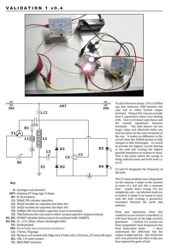
        This circuit is very appellative since all components are easy to find to me.
        Have someone replicated this device with success?

        The operation of this device is different of Bruce's v2.6, it's hard to me to understand how it work.
        There is any document with more technical information of this device?

        Have you already try a self-running configuration?
        There is more success replicators of this design?

        Thanks
        best regards,
        Henriques


        Originally posted by soundiceuk View Post
        As soon as I can I will post a comparison schematic with Bruce's v2.6

        I have also included the pdf of the schematic for a clearer printable version.

        PLEASE NOTE: Page 2 is additional information on Mystery coils.

        This document is in the early stages and my intention is to fill it with validations to help raise awareness of the technology we are trying to refine.


        https://dl.dropbox.com/u/33118048/Va...201%20v0.4.pdf


        Graham I value your input and after seeing your build, I'm looking forward to seeing what scope you have
        Comment


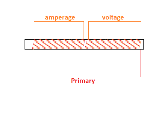
        • Awesome coil design, I like it.
          I wonder how it would work incorporated into Don Smiths device.
          Half of the Answer is knowing the right Question

          Comment


          • @ prato_braun & Peculian -Thanks for the kind words of support!

            I'm really sorry I haven't responded lately. I have had computer and relationship problems.

            I decided to post to try and clear up some of the remaining questions, even though a - d are not ready.

            The frequencies change slightly from location to location.

            The lower or higher frequencies can be used or even combined.

            Infact they can be combined in so many ways with various harmonics nothing has been nailed down completely yet. This is a minefield in itself.


            @ c_henriques - The validation circuit was independently produced by a private engineer as a learning tool to help him validate what Bruce is attempting to teach.

            These were the only components he had on standby.

            From what I know C4 is charged via induction.

            @ Neo1 - Did you have any luck finding a cap with roughly the same capacitance? How were you measuring the capacitance and what with?


            What information from the validation schematic is missing to enable folks to replicate?


            The latest postive news I have heard is a simple self running proof of concept is being produced, although I would be glad to see an independent version of the validation circuit with GSM's self running modifications applied.

            @ GSM

            I'm looking forward to producing something you can warm up the soldering ion for.

            Still some unanswered questions to wrap up in this thread. I'm lost in my email inbox.

            Comment


            • Hi, I was using a capacitance/inductance meter to measure for the 75pF and have had no luck find a suitable capacitor. I am looking forward to a version that is simple to replicate and uses off the shelf parts.

              I know that the knowledge is now available!

              Anyone serious about wanting to overturn the current systems of control and suppression will see through the desire for monetary gain, or personal recognition, and see that the value perceived in money will have no value at all once the truth becomes clear, and that tapping the environment for FREE energy that is all around us is our ultimate destiny, as the awareness is now held in the morphogenetic field.

              Kris

              Comment


              • Originally posted by Neo1 View Post
                Hi, I was using a capacitance/inductance meter to measure for the 75pF and have had no luck find a suitable capacitor. I am looking forward to a version that is simple to replicate and uses off the shelf parts.

                I know that the knowledge is now available!

                Anyone serious about wanting to overturn the current systems of control and suppression will see through the desire for monetary gain, or personal recognition, and see that the value perceived in money will have no value at all once the truth becomes clear, and that tapping the environment for FREE energy that is all around us is our ultimate destiny, as the awareness is now held in the morphogenetic field.

                Kris
                Hi Kris

                Why don't you make a cap from 2 small sheets of aluminum?

                Regards

                John

                Comment


                • Originally posted by soundiceuk View Post

                  The frequencies change slightly from location to location.
                  Antenna-ground reactions will have different relationships in different locations, with some locations being much more stably coherent than others.

                  Thus I wonder if recorded frequencies have been noted changing at any fixed location (due to molecular changes within the earth caused by entirely natural solar events/ relations, or crustal stresses) ?

                  Cheers ....... Graham.

                  Comment


                  • I think this is relevant here as well

                    In a gas discharge, such as a fluorescent lamp, current causes resistance to decrease. This is because as more electrons and ions flow through a particular area, they bump into more atoms, which frees up electrons, creating more charged particles. In this way, current will climb on its own in a gas discharge, as long as there is adequate voltage (and household AC current has a lot of voltage). If the current in a fluorescent light isn't controlled, it can blow out the various electrical components.
                    Half of the Answer is knowing the right Question

                    Comment


                    • Unique Crystal Radio

                      The coil design is very interesting I was thinking on how to incorporate this into the Don Smith system and came up with this.
                      Half of the Answer is knowing the right Question

                      Comment


                      • Theory is definately important Dave45

                        This link is courtesy of John Galloway


                        An Explanation of how the "Mystery Crystal Radio" Works

                        Mystery Crystal Radio circuit analysis

                        Comment


                        • From my basic understanding a simple experiment can be carried out using an antenna, earth grounding rod and mystery coil to find out what voltage can be measured peak to peak for your elevation.

                          This will allow you to improve your earth ground and higher surface area antenna design and measure the day to day fluctuations.

                          Those with scopes will be able to monitor frequencies in there area with tuning added.

                          Look for the frequency on this page - 1.094mhz

                          http://www.energeticforum.com/203073-post31.html


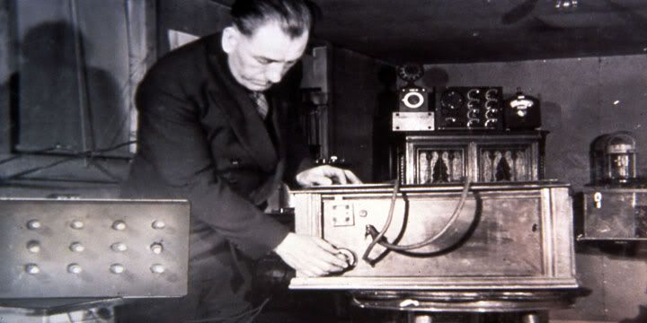
                          We believe this photograph of Moray shows the back of his device and that he is tuning his antenna.


                          Here is some of the more recent research for those who are interested.


                          Sire of time (keeper of time)

                          Saturn, Source of Measure


                          Old Father Time

                          Old Father Time


                          Discovery
                          Immediately after the discovery of Jupiter's decametric radio emissions in 1955, attempts were made to detect a similar emission from Saturn, but with inconclusive results. The first evidence that Saturn might have an internally generated magnetic field came in 1974, with the detection of weak radio emissions from the planet at the frequency of about 1 MHz.

                          Magnetosphere of Saturn - Wikipedia, the free encyclopedia


                          Saturn Radio Noise

                          https://www.dropbox.com/s/v9hdzmh7k4...%20noise.mp3?m

                          The Radio Sun

                          The Radio Sun

                          Comment


                          • Originally posted by Neo1 View Post
                            Ok - C4 and C5 - So I have just gone through my entire collection electrolytic caps and yes they do vary a little in voltage and capacitance, several are in the range of the 3300uf @50v, however nothing i have comes anywhere near close to the 70pf terminal to case capacitance. Most are up in the 1 to 6uf range and the lowest value is 600nf.

                            With C5 @70pf and being an integral part of the tuned cct, it looks like this is going to be an interesting cct to get to work in its current configuration.

                            Someone may want to double check that capacitance reading for C4 - case to terminal - as the parameter for this component does not make it an off the shelf part.

                            Anyone have a work around?

                            Kris
                            Q. Do you happen to know the brand of 3300pf electrolytic you used that happened to have the 70pf case to terminals?

                            A. They are labeled Xicon, I'm not sure what I took them out of. Even if it's not exactly right you can simply dial the variable capacitor to a lesser capacitance to offset the difference or simply adjust what you have with a foil cover.

                            You can also adjust the coil to set the resonance based on the value of the cap. Lots of work arounds if one is creative...

                            Comment


                            • Thanks for your response

                              Regarding the 70pF - thanks for your reply -I welcome the response from the engineers as with a cct that is harnesing this type of energy I feel it is important to get the direction from the engineers as they are going to have a clear understanding of what specific interaction is taking place and thus required from that part of the cct in order to obtain the desired results. Cool!
                              1

                              Comment


                              • Originally posted by soundiceuk View Post
                                @ c_henriques - The validation circuit was independently produced by a private engineer as a learning tool to help him validate what Bruce is attempting to teach.

                                These were the only components he had on standby.

                                From what I know C4 is charged via induction.
                                Hi soundiceuk,

                                About 2.6 proof of concept when you talk about heterodyne what's happen?
                                1) there is a non-linear component to mix (multiply) the frequencies of the two waves (BFO wave and thunderstorms wave) - sin(x)*sin(y)=1/2cos(x-y)-1/2cos(x+y)

                                2) or there are a sum of the two waves and the resulting wave is the average frequency multiplied for a periodic wave whose the frequency is the difference of the frequencies.


                                About 0.4 validation
                                It is the same principle that the 2.6 proof? This 0.4 validation also works at 3.5Mhz range?

                                The primary coil L1 vibrates at a slightly different frequency of the thunderstorms waves (generated on antenna and tank L2) ???
                                Why the frequency generated on L1 is different? is it due to the L1 inductance and C1 capacitance?

                                Very thanks,
                                Henriques

                                Comment

                                Working...
                                X