Announcement

Collapse
No announcement yet.

- 5x More Current Out Than In - Validation Of Proof Of Concept -

Collapse
X
 
  • Filter
  • Time
  • Show
Clear All
new posts

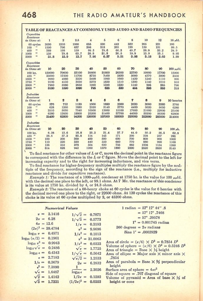
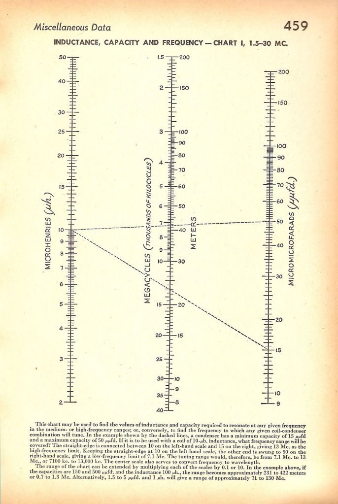
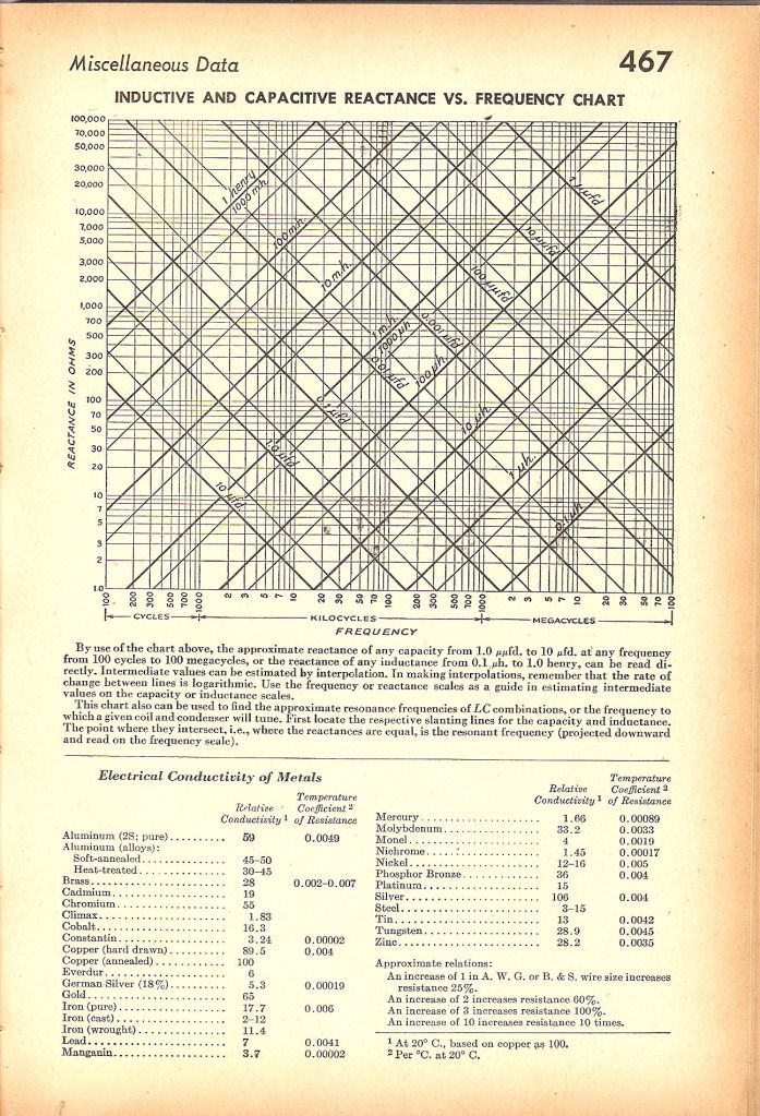
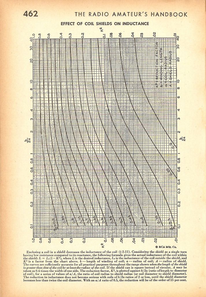
  • Scans 1945 radio book

    Hi

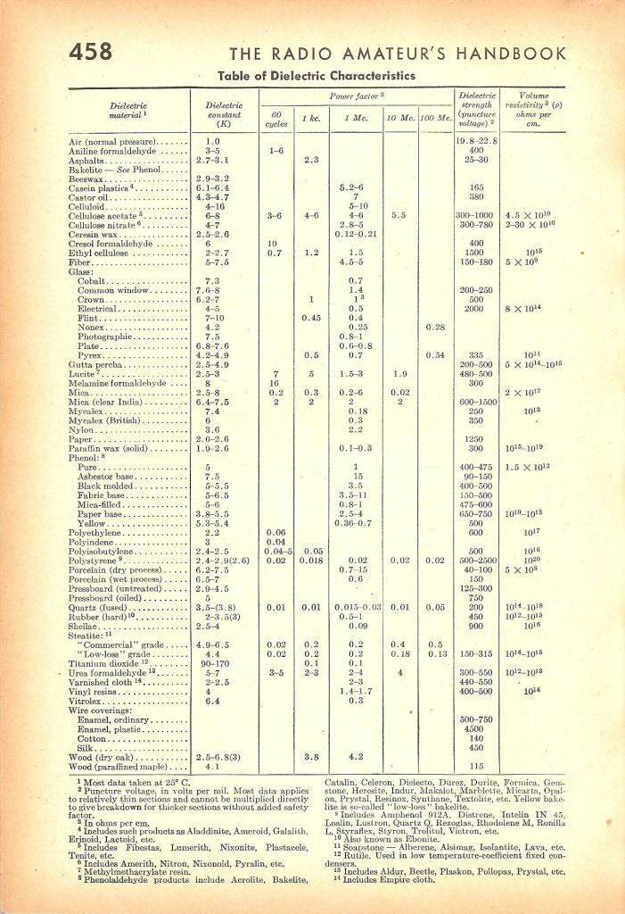
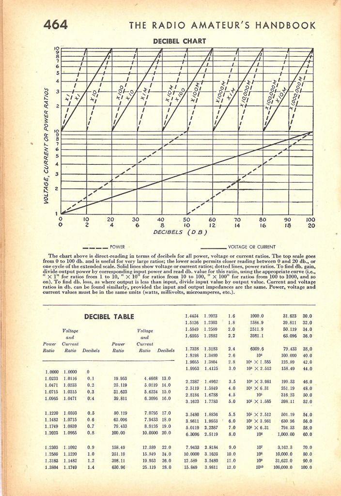
    I have scanned a few pages of graphs etc that may be helpful in understanding this device.


    Regards

    John

    Comment


    • Hey all,

      I've attempted to replicate the circuit as shown on this thread (https://dl.dropbox.com/u/33118048/Ra...eiver-v2.5.pdf).

      I couldn't get the circuit going, though I'm not sure how to connect the radio tuning capacitor, and whether or not the crystal oscillator is suitable for the job.

      I was unable to measure the capacitance of the radio tuning capacitor, and it has 3 terminals coming out of it.
      60 - 160pF Miniature Tuning Capacitor - Jaycar Electronics

      The crystal oscillator is a two pin connected 3.5795MHz
      3.5795MHz Crystal - Jaycar Electronics

      I've verified the coil using an inductance meter, and the earth connection from the circuit board is connected to a soldering iron which is connected to the electrical earth / earth stake on the side of the house.

      Earth connection:
      ImageShack® - Online Photo and Video Hosting

      I could only get a 6v 55 watt bulb, although it didn't show any sign of lighting up.

      Any help in getting this circuit going would be much appreciated. Thanks for that

      Andrew from Panacea

      Circuit board:
      ImageShack® - Online Photo and Video Hosting

      Circuit board tracks & tuning capacitor connectors:
      ImageShack® - Online Photo and Video Hosting
      Last edited by ashtweth; 08-17-2012, 01:47 AM. Reason: The images didn't display.

      Comment


      • How you connect the oscillator?
        look this https://www.dropbox.com/s/pyvyg49sbe...28%20BFO.pdf?m

        I think that with this bulb it will not work, try a less power bulb.

        Comment


        • The oscillator is connected in series between the input battery positive terminal, and the LC resonant circuit.
          The circuit diagram showing how we connected it is at the top of the PDF document in the following link: https://dl.dropbox.com/u/33118048/Ra...eiver-v2.5.pdf
          Being only a two pin crystal, there is no connection to the negative, only in series on the positive side.

          You could be right about the light bulb - maybe the proof of concept receiver doesn't like low impedance loads. I'll see what else I can get my hands on.

          I had a look at the document link you provided - thanks for that
          It looks like the capacitor or inductor in series shifts the frequency of the crystal oscillator. I will keep that in mind.

          Andrew from Panacea

          Originally posted by c_henriques View Post
          How you connect the oscillator?
          look this https://www.dropbox.com/s/pyvyg49sbe...28%20BFO.pdf?m

          I think that with this bulb it will not work, try a less power bulb.

          Comment


          • Originally posted by soundiceuk View Post
            I have also seen high wattage designs working and so have the engineering team. They are working on them in their spare time. We are all volunteers.

            We are much further ahead with this project than most would believe.
            Two options.

            The selfish / greed route.

            or the way we are attempting.

            We can rock and roll with each other or walk away from each other.
            If I could point out that the second option does not have to take the form you guys are using.

            Here's what I'd do....

            You guys alledgedly have working (though uncontrollable at this point) high power output. Rather than acting all coy about this, make a couple of spectacular Tesla-esque demo videos of a couple of batteries connected to your device blowing something up.

            That'll go viral instantly.

            It doesn't matter that it's unconrollable and dangerous and to be honest the theory is less important than the result from my perspective. Not marketing in the traditional sense, but for awareness purposes.

            Also, look at non-profit software foundations like Mozilla and Wikipedia. They have very sustainable working business models based on donations and advertising. For most people to donate though, we'll need to see high power evidence, controllable or not.

            On a similar software slant, make the project truly open. If the goal is to release this for free (and looking at the income of Wikipedia etc, this doesn't mean for nothing) is the goal then it doesn't matter if it isn't controllable at the moment.

            So your action plan should be (imo):

            1. Forget about liability issues, if you are releasing scientific research rather than a product you don't have any liability. They'll be releasing research material to be acted upon by competent people in a safe environment.

            2. Make couple of videos of something spectacular - some unfused relatively high power device starting to smoke from the output of a couple of AA cells or whatever it is. Put that everywhere, including the front page of the site.

            3. Put a giant donate button on the site. We shouldn't have to click into places and subscribe to stuff to donate on a whim. The donate link strangely hidden away in the first post on the third thread of the forum to donate isn't working here.

            4. Get the info out there to every single reporter, blogger, forum, net-energy importing government, media-friendly environmental activist and, of course, university on the planet.

            But yeah, fix the donate thing.

            I hope this is seen as positive and constructive, because I really want to see something like this work.

            Cheers

            Paul
            Last edited by Regster; 08-18-2012, 12:39 PM.

            Comment


            • Originally posted by c_henriques View Post
              Hi soundiceuk,

              About 2.6 proof of concept when you talk about heterodyne what's happen?
              1) there is a non-linear component to mix (multiply) the frequencies of the two waves (BFO wave and thunderstorms wave) - sin(x)*sin(y)=1/2cos(x-y)-1/2cos(x+y)

              2) or there are a sum of the two waves and the resulting wave is the average frequency multiplied for a periodic wave whose the frequency is the difference of the frequencies.


              About 0.4 validation
              It is the same principle that the 2.6 proof? This 0.4 validation also works at 3.5Mhz range?

              The primary coil L1 vibrates at a slightly different frequency of the thunderstorms waves (generated on antenna and tank L2) ???
              Why the frequency generated on L1 is different? is it due to the L1 inductance and C1 capacitance?

              Very thanks,
              Henriques
              Hi Henriques, the engineers are on holiday at the moment and Bruce is in bed sick.

              I will try my best to give you some information, although it may not completely answer your questions entirely.

              The way I understand it, the whole point of the circuit is to create a draft / pressure difference (vacuum).

              Open two windows in your house and doors can start opening and slamming on there own. Remove the doors completely and you have a draft.


              Using the analogy of water is how I learned about electricity, so I will try to explain my understanding that way.

              The planet earth is surrounded by water (ions).

              When one of these circuits is built correctly it becomes a "sink hole" or "pipe" that creates a difference in pressures, so that the water (ions) is encouraged into the hole (circuit) like a syphon action. We believe a vortex action could add massively to the ouput, although as far as I know no one has tried it yet, but the theory is there in some detail.

              We believe a number of frequencies can be combined in a number of ways to create a vortex.

              I haven't fully understood that part yet, so my explanation is quite basic.

              The way I see the tank circuit is a bit like sitting in the bath with the tap on and moving your body backwards and forwards in time so the water goes higher and higher each time.


              One of the other things that is being explored are regenerative circuits, which were used in radios of the late 1920's early 1930's.


              Here is a little Q & A from me to the engineers.

              Q. Is there any alpha fusion taking place in the proof of concept circuit?

              A. No, there isn't any alpha fusion.


              Q. So, if there is no alpha fusion which part does the excess energy come from?

              A. It comes from the atomic decay from the planetary IONS that are created from natural radiation processes as is outlined in the 2nd Edition.


              Q. Ok, imagine I'm a lonely little ION floating around near the antenna.

              Why am I encouraged to travel onto and along the antenna on the proof of concept circuit and how do I turn into an electron in the circuit?

              A. My understanding of the process is that the mostly positive IONS in the air and the mostly negative IONS in the ground are attracted to each other. The negative IONS in the ground cling to the ground rod where they lose their negative charge to the positively charged circuitry that is electrically connected to the antenna. There is an electrical current that takes place in the wires because electrons in the wires travel away from the negatively charged ground rod towards the positively charge antenna.

              I hope I've explained the process correctly and anyone is open to correct me where I might be wrong.


              I may have a slightly different understanding - I see the earth and air as a continuously neutralizing flow of pos and neg. The earth contains both charges and is neutral as does the air. Both are in continuous change based on natural occurrences that alter these charges. For instance in storm where the clouds are charged highly negative.... since negative charges repel each other the earth below becomes positively charged. If we place a HV neg charge on an antenna it will repel all neg charges around it and attract a positive charge, the same would happen in an earth connection.

              Experimenting with HV DC charges I found you can charge a capacitor by placing a sphere in a HV neg condition and bring a point in close proximity to the sphere. Between the ground and point you place a capacitor that you want charged. The sphere ( neg charge ) makes the point a concentrated pos charge which then creates a neg plate on the capacitor and the ground side attracts the pos charge from earth. Since this process only happens once at the point of connection in order to continually charge the cap you need to neutralize one of the components. If we ground the point in a pulsing manor we can bring the cap charge to extremely high levels. Since there is no exchange of electrons between the point and charged sphere there is no power required to set this process in motion other than the initial charging of the sphere.

              If this process is reversed, such as a positively charged sphere there will be an endless flow of neg charge at the point - in which case the capacitor would be charged neg on the ground side. This to me is a natural DC flow, natures diode.

              If we take, for instance, tesla's basic radiant energy patent and have an antenna connected to a capacitor then to ground the plates of the capacitor will gather their respective charges based on surrounding conditions. Once nature has "balanced" the charges it remains dormant until something occurs to alter that charge. A spark gap and coil will neutralize the plates and the process begins over again. As long as we continue to neutralize the plates nature will continuously bring them back to balance, or a charged state. As long as we can maintain the neutralizing process nature will continuously try to maintain a balance.

              In his patent he states that connecting the capacitor to ground and an antenna or plate as the "simplest" method to create the initial imbalance people tend to overlook what he eludes to in only a brief mention. As stated in his patent "the second terminal or armature of the condenser may be connected to one of the poles of a battery or other source of electricity or to any conducting body or object whatever of such properties or so conditioned that by its means electricity of the required sign will be supplied to the terminal. " People tend to dismiss this when reading the very next statement explaining the simple way of supplying a natural pos and neg and their results are poor but successful for very low power applications.

              I see it as forming a natural battery by maintaining a HV charge on one terminal and allowing nature to supply to opposite charge to the other. Once nature balances this charge we neutralize it and allow the process to start over. The action of neutralization becomes our useable output. Our circuits are simply a method of creating a continuous imbalance/neutralization process that because of this process can be transformed into a useable output.

              The disassociation of matter may enhance the process considerably but I don't believe it's necessary to achieve our goals.


              Here is an interesting research patent.

              James Marion Fisher, Covington, Ky., assignor to The Radiant Energies Corporation, Cincinnati,. Ohio, a corporation of Ohio. Application July 1'1', 1934

              https://dl.dropbox.com/u/33118048/2143437.pdf

              Comment


              • Originally posted by ashtweth View Post
                Hey all,

                I've attempted to replicate the circuit as shown on this thread (https://dl.dropbox.com/u/33118048/Ra...eiver-v2.5.pdf).

                I couldn't get the circuit going, though I'm not sure how to connect the radio tuning capacitor, and whether or not the crystal oscillator is suitable for the job.

                I was unable to measure the capacitance of the radio tuning capacitor, and it has 3 terminals coming out of it.
                60 - 160pF Miniature Tuning Capacitor - Jaycar Electronics

                The crystal oscillator is a two pin connected 3.5795MHz
                3.5795MHz Crystal - Jaycar Electronics

                I've verified the coil using an inductance meter, and the earth connection from the circuit board is connected to a soldering iron which is connected to the electrical earth / earth stake on the side of the house.

                Earth connection:
                ImageShack® - Online Photo and Video Hosting

                I could only get a 6v 55 watt bulb, although it didn't show any sign of lighting up.

                Any help in getting this circuit going would be much appreciated. Thanks for that

                Andrew from Panacea

                Circuit board:
                ImageShack® - Online Photo and Video Hosting

                Circuit board tracks & tuning capacitor connectors:
                ImageShack® - Online Photo and Video Hosting
                Try with LEDs to get the tuning closer.

                What are you reading on your antenna and earth peak to peak?

                What are you using for you antenna?

                What is your elevation / location?

                I am preparing 2nd Edition 0.13 BETA 4 with an updated schematic.

                I have a few software problems at the moment.

                Adobe Acrobat X has just stopped working!

                Comment


                • Originally posted by Regster View Post
                  If I could point out that the second option does not have to take the form you guys are using.

                  Here's what I'd do....

                  You guys alledgedly have working (though uncontrollable at this point) high power output. Rather than acting all coy about this, make a couple of spectacular Tesla-esque demo videos of a couple of batteries connected to your device blowing something up.

                  That'll go viral instantly.

                  It doesn't matter that it's unconrollable and dangerous and to be honest the theory is less important than the result from my perspective. Not marketing in the traditional sense, but for awareness purposes.

                  Also, look at non-profit software foundations like Mozilla and Wikipedia. They have very sustainable working business models based on donations and advertising. For most people to donate though, we'll need to see high power evidence, controllable or not.

                  On a similar software slant, make the project truly open. If the goal is to release this for free (and looking at the income of Wikipedia etc, this doesn't mean for nothing) is the goal then it doesn't matter if it isn't controllable at the moment.

                  So your action plan should be (imo):

                  1. Forget about liability issues, if you are releasing scientific research rather than a product you don't have any liability. They'll be releasing research material to be acted upon by competent people in a safe environment.

                  2. Make couple of videos of something spectacular - some unfused relatively high power device starting to smoke from the output of a couple of AA cells or whatever it is. Put that everywhere, including the front page of the site.

                  3. Put a giant donate button on the site. We shouldn't have to click into places and subscribe to stuff to donate on a whim. The donate link strangely hidden away in the first post on the third thread of the forum to donate isn't working here.

                  4. Get the info out there to every single reporter, blogger, forum, net-energy importing government, media-friendly environmental activist and, of course, university on the planet.

                  But yeah, fix the donate thing.

                  I hope this is seen as positive and constructive, because I really want to see something like this work.

                  Cheers

                  Paul

                  I like your suggestions.

                  We are heading in the right direction, but slowly.


                  Very interesting you should mention the Donate button in this thread.

                  I have edited the link a number of times.

                  An outside influence keeps making it into a link that doesn't work.


                  I have just donated a box of brand new components worth approx £100 to the engineer that built the proof of concept validation circuits.

                  I have a few more boxes of parts to also send him.


                  This week I will be posting his working schematic of Bruce's v2.6 using the Armstrong oscillator also used in the validation v0.4.

                  I think when this is posted things will become clearer.


                  I have identified that our the engineer I am donating components to needs a tripod and decent video camera to capture the goods properly for us.

                  I do not have these items to lend and I'm broke at the moment. The next bit of spare cash I have will pay to send some more components that I have gathered.

                  Some hydroponics white - black - white grow film would also brighten up his workshop and help the video quality massively.

                  A circuit melting to bits would definitely tell the story.

                  One way of obtaining high power is to charge the antenna negatively with HV and replace the off the shelf detector diodes for ion valves.

                  Comment


                  • @ john_g

                    Thank you for taking the time to post this very interesting information.

                    Comment


                    • Originally posted by soundiceuk View Post
                      I like your suggestions.

                      We are heading in the right direction, but slowly.
                      I have just donated a box of brand new components worth approx £100 to the engineer that built the proof of concept validation circuits.

                      I have a few more boxes of parts to also send him.
                      I have identified that our the engineer I am donating components to needs a tripod and decent video camera to capture the goods properly for us.

                      I do not have these items to lend and I'm broke at the moment. The next bit of spare cash I have will pay to send some more components that I have gathered.
                      Thanks very much for your reply. Apologies for selectively quoting you, but I have to say that those parts don't give too good a signal.

                      My phone takes as good (roughly) a video as my HD camcorder. If these guys are actually in New Hampshire then they'll have a friend or member of family with a camcorder or HD smartphone. That excuse for money sounds a bit.. well... "Nigerian".

                      Have you spoken with them?

                      Comment


                      • Originally posted by Regster View Post
                        Thanks very much for your reply. Apologies for selectively quoting you, but I have to say that those parts don't give too good a signal.

                        My phone takes as good (roughly) a video as my HD camcorder. If these guys are actually in New Hampshire then they'll have a friend or member of family with a camcorder or HD smartphone. That excuse for money sounds a bit.. well... "Nigerian".

                        Have you spoken with them?
                        Bruce is the only one in New Hampshire.

                        I'm not asking for a donation if that's how it reads.

                        I'm certain we can sort something out between us.

                        The engineer has his own youtube channel and camera & Bruce made nearly all the Don Smith videos.

                        I would like to see a decent camera & tripod end up in the hands of this particular engineer. Especially as he has achieved a decent output without any radioactive ores or isotopes prior to meeting Bruce.

                        Infact it's a very strange coincidence that they have been working on the same circuit individually, without even knowing each other.

                        Does anyone believe in fate?

                        I have not met anyone from Energetic in person or spoken on the telephone.

                        I have nearly 3000 emails from Bruce since Feb 2012 though.

                        Not enough hours in the day I'm afraid

                        Comment


                        • Cheers, I wasn't implying that you were soliciting donations but highlighting that for an ordinary guy like me to get behind this and donate I'd need to see some evidence and *cough* also *cough* be able to.

                          To be honest, at this stage it all seems a bit cloak and dagger for my liking. Especially the (paraphrasing) "we have high power working, but can't release because of liability worries, please donate to get us to the next level" thing. I'm not into the whole MIB theory and can't understand people who aren't completely open source who are.

                          I'll watch with interest. I'm not a rich man, but I'll donate regularly and encourage everybody to get behind it if I know for sure it's real.

                          But to the layman, talk of camcorders seems a bit cuckoo when we're alledgedly on the verge of a world breakthrough.

                          All the best,

                          Paul

                          Comment


                          • Many thanks for that

                            Do you recommend using an oscilloscope to try and measure the peak to peak voltage between the antenna and earth?

                            I'm using a ~21m length of copper wire, approximately 1mm thick. The antenna is at least 10 feet from the ground. The wire is currently strung in an east / west orientation.

                            My location is Loganlea QLD (Australia), and the elevation is approximately 23m above sea level.

                            I'm looking forward to viewing the updated edition & schematic

                            I tried measuring the voltage (AC & DC settings) and frequency between the output of the crystal oscillator and the battery negative. I couldn't get a reading. I measured the voltage across the crystal oscillator and got the battery voltage.

                            Any help is always much appreciated, and will contribute any feedback back in to the project

                            Andrew from Panacea

                            Originally posted by soundiceuk View Post
                            Try with LEDs to get the tuning closer.

                            What are you reading on your antenna and earth peak to peak?

                            What are you using for you antenna?

                            What is your elevation / location?

                            I am preparing 2nd Edition 0.13 BETA 4 with an updated schematic.

                            I have a few software problems at the moment.

                            Adobe Acrobat X has just stopped working!

                            Comment


                            • Originally posted by Regster View Post
                              Cheers, I wasn't implying that you were soliciting donations but highlighting that for an ordinary guy like me to get behind this and donate I'd need to see some evidence and *cough* also *cough* be able to.

                              To be honest, at this stage it all seems a bit cloak and dagger for my liking. Especially the (paraphrasing) "we have high power working, but can't release because of liability worries, please donate to get us to the next level" thing. I'm not into the whole MIB theory and can't understand people who aren't completely open source who are.

                              I'll watch with interest. I'm not a rich man, but I'll donate regularly and encourage everybody to get behind it if I know for sure it's real.

                              But to the layman, talk of camcorders seems a bit cuckoo when we're alledgedly on the verge of a world breakthrough.

                              All the best,

                              Paul

                              Hi Paul, I was kindly donated a Dell Core2duo laptop and desktop by one the members when my pc went down from a virus.

                              Now there may have been someone reading who has loads of old cameras / tripods lying around or has something for sale on ebay, who knows.

                              MIB theory

                              I know two members of this forum who have been visited at their homes in the UK after showing videos showing devices with too high of an efficiency for the establishment to allow. One had parts stolen and death threats made to him and his family and the other had parts and equipment stolen.

                              I don't know how old you are or what your life experience is, but my own life experience has proven to me that things definately go on behind the scenes and legal systems.

                              I realise that nothing can be completely protected but I do offer some form of protection to the people that have volunteered to help, however thin this may be.

                              I'm not a rich man and I donate my time and money freely to help perpetuate the technology. I appreciate folks need and want to see more action before getting financially involved.

                              I have just remembered that I have a nearly new USB HD web camera in a box in the attic.

                              I wear my heart on my sleeve and often talk my thoughts out loud, in the hope it will create a new or better idea. Sometimes this comes from myself and sometimes it doesn't.

                              Thanks for the feedback.

                              Comment


                              • Originally posted by ashtweth View Post
                                Many thanks for that

                                Do you recommend using an oscilloscope to try and measure the peak to peak voltage between the antenna and earth?

                                I'm using a ~21m length of copper wire, approximately 1mm thick. The antenna is at least 10 feet from the ground. The wire is currently strung in an east / west orientation.

                                My location is Loganlea QLD (Australia), and the elevation is approximately 23m above sea level.

                                I'm looking forward to viewing the updated edition & schematic

                                I tried measuring the voltage (AC & DC settings) and frequency between the output of the crystal oscillator and the battery negative. I couldn't get a reading. I measured the voltage across the crystal oscillator and got the battery voltage.

                                Any help is always much appreciated, and will contribute any feedback back in to the project

                                Andrew from Panacea
                                Hi Andrew, I would say yes to the scope unless you have a digital meter capable of reading fast enough. I'm guessing a DMM would average the readings or read the highest peak.

                                I'll get the schematic finished ASAP.

                                Cheers,

                                Paul

                                Comment

                                Working...
                                X