Announcement

Collapse
No announcement yet.

- 5x More Current Out Than In - Validation Of Proof Of Concept -

Collapse
X
 
  • Filter
  • Time
  • Show
Clear All
new posts

  • I was under the impression that the ion valve aka radiant energy detector diode was providing power from a LENR reaction.

    This is what Bruce had to say about the matter.


    My work with radiant energy has nothing to do with obtaining energy with fusion.

    Fusion is just another stored energy.

    The alpha fusion valve in my patent describes a high voltage, high frequency diode which gains its required free electrons for inter electrode conduction through the generation of a heated cathode obtained from the alpha fusion. This effectively does away with the requirement of an external direct current source to heat the cathode.


    1. The ion valves are the keys that unlock the energy that flows through the circuits.

    2. The valve in my patent can contain a conductive vapor, gas, or even a vacuum. It all depends on the application you want them to assist.

    There is no alpha fusion that takes place in the proof of concept circuits. The energy comes from Planetary IONS.
    Comment


    • Can you get a timescale on when there will be a fully documented, replicable proof of concept that shows increased power output that will 100% work?

      Btw, when I said that the PayPal link didn't work, I meant the one on the Earth ION forum/site. Maybe wrapping them in [url ] tags would do the trick.

      Comment


      • Thanks for the heads up on the paypal link. I wish whoever keeps changing it on this thread would stop changing it. I guess I should have asked permission first, but as it isn't for financial gain, I assumed there would be no problem.

        The Q&A on the Earth ION Energy site needs a lot of work I know. I haven't had much time lately because of family issues.


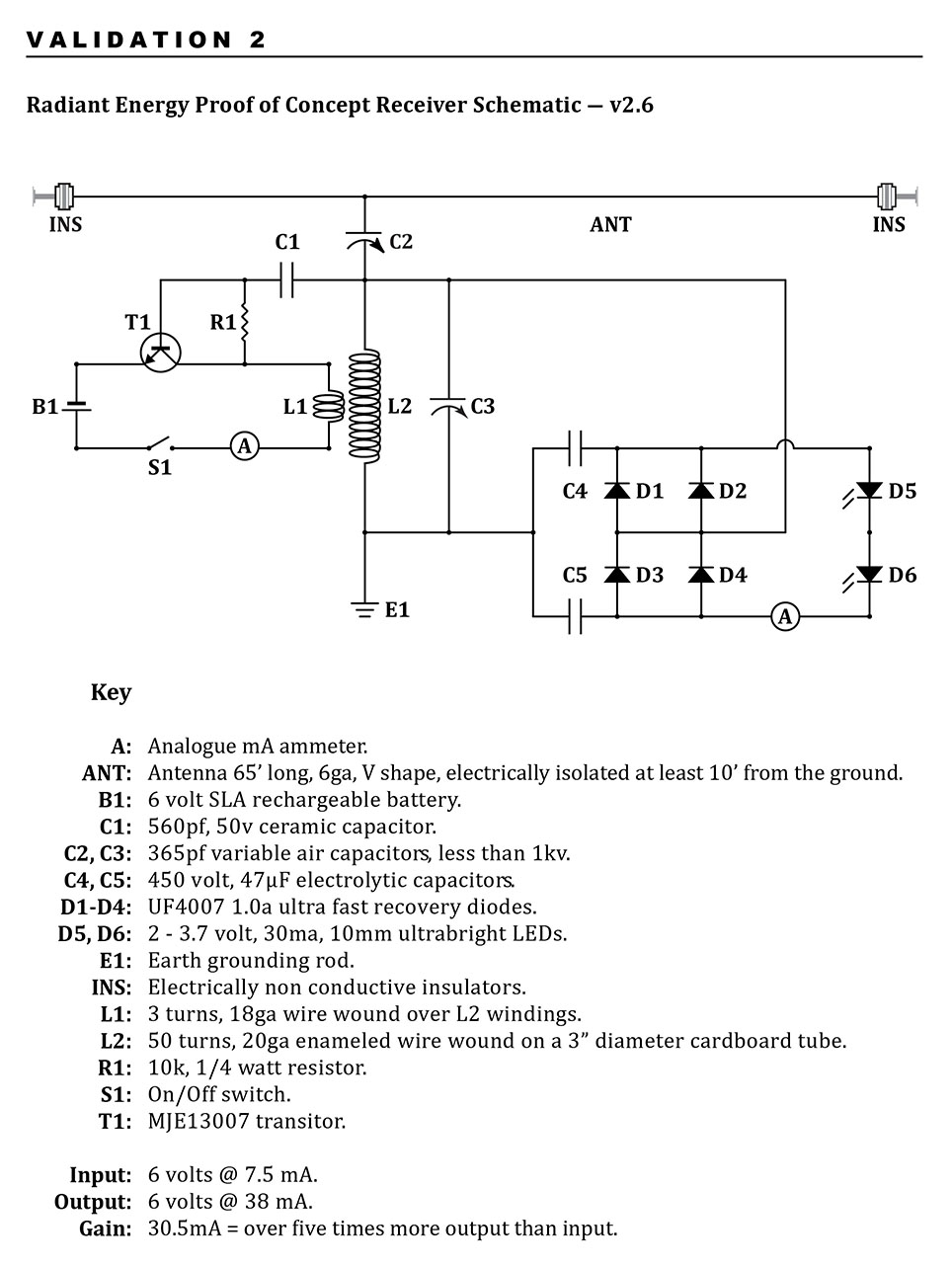
        Here is VALIDATION 2 which gets around using the 3 plate capacitor issue that replicators were having.


        - PRIVATE ENGINEER -

        Since I'm not tuning for a radio station per say and more looking for a response the antenna might only need to be a mass. I put together a basic AM loop antenna that I've been testing with some other circuits and it seems to provide the feed back fairly well, I've also found with some circuits a 15ft long wire works well which leads me to believe it's more related to mass. I'm up in the air about the antenna ( size, length, shape ) - I simply don't know at this point and still learning, it's still an unknown variable that might change with every other variable of the build. Wish I could be more specific. The one I'm playing with now is the " R & D Loop" from Dave's Homemade Loop Antennas at MAKEARADIO.COM

        I wound the mystery coil with 20 ga wire for both coils. I didn't use the 25 turn coil with the original and wound a separate coil around it for that one. The form was a 3" diameter cardboard shipping tube. I would imagine the 24 ga wire would increase the inductance somewhat - not sure how much difference it would make.

        Since the unit makes very little power the 4148's work well, I used the UF4007's on this one. I never tried the schottky's as I didn't have any to hand.

        I used 2 - 47uf 450 volt caps on this one - again this is another variable that might require some experimentation - maybe it would work well with larger ones.

        The grounds are at an advantage the deeper you can get them. A well pipe makes a very good ground as it connects into the water table. We also have a very high iron content in the ground here which I'm sure helps in the electrical activity. A shallow grounding will need to be kept wet - if rods are used I would sink several of them in a circle and connect them all together then put a sprinkler over them for a few hours to really saturate the area. A lake or stream might work very well also...

        I'm sure everyone is going to end up with something a little different than the original with varying degrees of successes and/or failures because of all the variables - hopefully getting one to work better than mine. I spent 6 hours tuning, tweaking and swapping parts to get it working as shown. Everything will affect it's operation.

        It's not just the components that can vary the outcome it's also the environment it's tuned to. If your sitting close to the circuit while tuning then you become a capacitive part of its environment, you may find that when you walk away it performs better or worse. A coffee cup - potted plant, electrical wiring in the home - everything absorbs or reflects energy and will have an impact on the outcome of these low power circuits. If someone built a circuit in their kitchen and tuned it perfectly showing positive results then took the same circuit without changing anything to the friends house to show them it might not work at all.

        There is no clear solution other than maybe creating a "standard" environment for the circuit - a box of sorts, faraday cage? - to reduce the unaccounted for variables.


        Bruce has given the thumbs up today for the release of the high wattage version into the public domain.

        I have the schematics in rough format at the moment and need to polish them up before publishing them. This should be done within a week.

        I believe a validation will follow the release within the next month.

        Comment


        • Thanks, so proof of the high power version is nigh!

          Fantastic news.

          Comment


          • One last question before the big reveal.... is the output current smooth or varying?

            Comment


            • Output current is DC to off the shelf or custom inverter

              We're still working on the best way to release this.

              The problem of Helium build up in Bruce's patent has been solved.

              Comment


              • So the battery can be used as a "starter motor" before the thing is self-running?

                Comment


                • I'm leaving the forum due to personal reasons.

                  Thank you to everyone for your input.

                  Those who want to stay in touch, you know where to find me.

                  Comment


                  • Hi Soundiceuk. I'm sorry to hear that. You were kind enough to grant a request of mine and I much appreciated it and honored what you asked of me. I see that others abused your kindness and that is a real shame. Wherever you go I wish you well.

                    Thanks

                    al

                    Comment


                    • Hi all

                      Just an idea (not mine but found on the net ) of how to do really simple and efficient variable capacitors

                      hope this helps

                      good luck at all

                      Laurent

                      diy variable capacitor 1 - YouTube

                      Comment


                      • Hey all,

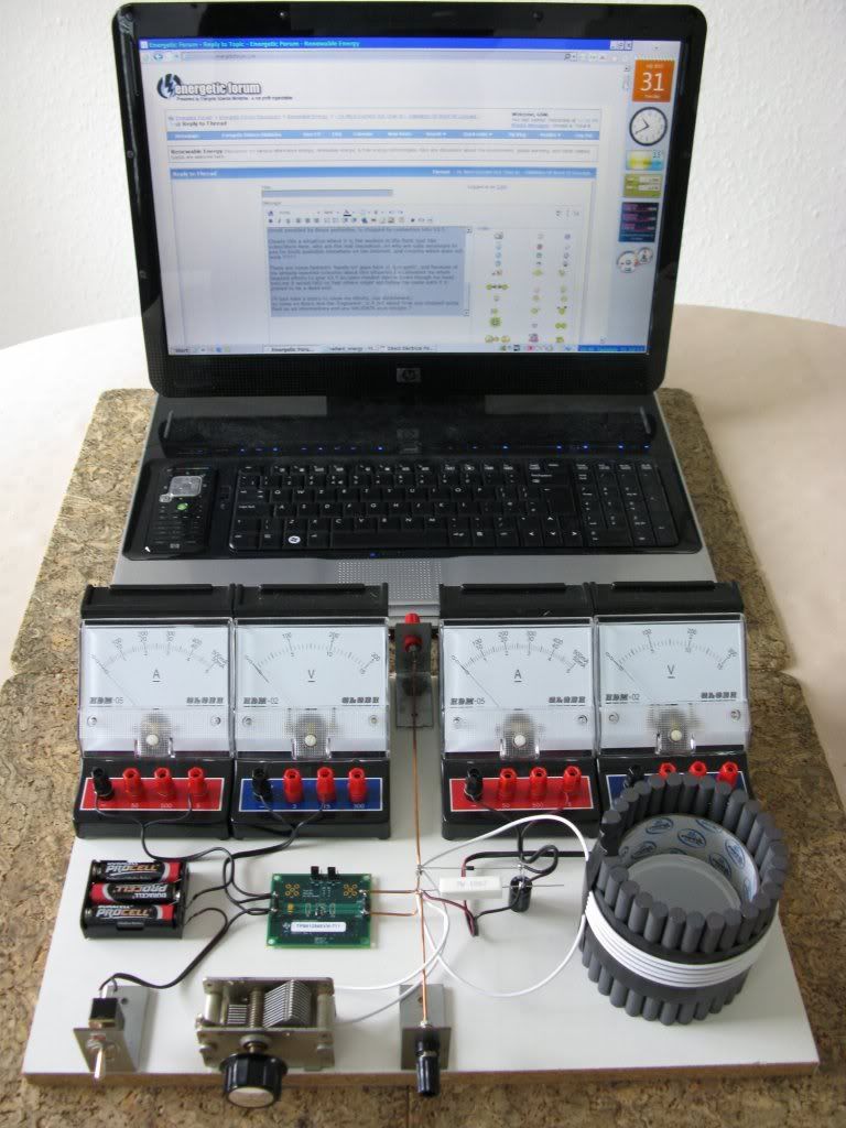
                        Just an update on tinkering with the v2.6 schematic of this circuit (page 25 of the 2nd Edition Proof v0.13 BETA4a PDF document). No luck so far - tried a few things and couldn't get it to light up the LEDs
                        http://imageshack.us/photo/my-images/19/imag01401.jpg/
                        http://imageshack.us/photo/my-images/850/imag01371.jpg/

                        I strung up a new antenna (PVC pipe, 90mm diameter, 3m / 10ft long, with 2mm zinc steel wire) as per the recommendations on this thread. Many thanks for that
                        http://imageshack.us/photo/my-images/228/imag01391.jpg/
                        http://imageshack.us/photo/my-images/845/imag01381.jpg/

                        I also put a zinc coated steel threaded rod into the ground (about 2 ft long).

                        I'm using standard miniature radio tuning capacitors (160pF) at the moment coupled with 50v capacitors in parallel to vary the capacitance range. Is this combination ok? I have just ordered a variety of larger style variable tuning capacitors so they'll probably do the job better.
                        http://imageshack.us/photo/my-images/254/imag01411.jpg/
                        http://stores.ebay.com.au/Interesting-Electronics

                        I tried bridging out C2 (variable capacitor) also. I don't understand how C2 comes into it. C3 is the tuning capacitor.

                        Any help would be much appreciated,

                        Andrew from Panacea

                        Comment


                        • @ All - Sorry, I nearly had a meltdown at home and needed a rest. I've also had computer trauma.

                          @ Woopy - Cheers for that great work!

                          @ Regster - Better than that - A radio signal can jumpstart the circuit.

                          @ Fan1701 - Thanks for the kind words.

                          @ GSM


                          So Graham back to your build.

                          You used a resistor in place of the bulb?

                          It didn't oscillate because of the low impedance.

                          Did you try any bulb?

                          The circuit looks great but what are the specifications of your earth & antenna?

                          I believe the basic tuning needs to be taken care of before trying to use the resistor for readings.


                          @ ashtweth

                          With your earth and antenna disconnected, what voltage do you measure peak to peak between them?

                          For a system that doesn't need radioactive sustances, a very decent earth is a must.

                          Some suggestions are using multiple earth grounding rods, deeper earths, watered ground, conductive cement to name a few.

                          I believe I read somewhere that Wardenclyffe had a 300' deep grounding rod.

                          Apparently it is fairly easy to make a deep hole using a water hose.

                          Comment


                          • PRIVATE ENGINEER

                            I would say his ground is a bit flimbsy if it's making any real connection at all. Maybe bolt a plate to the bottom of the rod and bury it as deep as possible and water the heck out of the ground around it. Even the 8ft rods that are used for house grounding are a bit lacking especially in dry areas. It seems like over kill for these small circuits but it makes a world of difference when you get a good connection with the earth.

                            Comment


                            • Helping Earth Connection

                              Originally posted by soundiceuk View Post
                              PRIVATE ENGINEER

                              I would say his ground is a bit flimbsy if it's making any real connection at all. Maybe bolt a plate to the bottom of the rod and bury it as deep as possible and water the heck out of the ground around it. Even the 8ft rods that are used for house grounding are a bit lacking especially in dry areas. It seems like over kill for these small circuits but it makes a world of difference when you get a good connection with the earth.
                              I read a while ago in an old radio book, that adding a copper sulphate slurry around the copper earthing rods helps improve performance.

                              Regards

                              John

                              Comment


                              • Good to see you back SoundIce.


                                Re my construction. I used a resistor because it has a higher cold resistance than an incandescent filament, and the 'oscillator' did not function as implied.

                                Something most significant is missing from either information or design relating to recent 'ion' circuits, and whilst I have not given up, I do not see anything which inspires me to try more at present, especially with such basic circuits similar to those I have used for radio in the past.
                                Also as Ashtweth has questioned; what is the purpose of C2 if the antenna is supposed to be collecting ionic charge ?

                                I'm study-reading much at present, and I am about to organise an attempt to video the radionic Blackrays permeating our atmosphere in order to illustrate the true source of excitations we are attempting to harness.

                                Cheers ........... Graham.
                                Last edited by GSM; 09-14-2012, 08:52 AM.

                                Comment

                                Working...
                                X