Announcement

Collapse
No announcement yet.

Open discussion for projects on this forum.

Collapse
X
 
  • Filter
  • Time
  • Show
Clear All
new posts

  • Dear Seth

    Originally posted by s e t h View Post
    can someone explain to me how a dc pulse circuit through a nice coil, for instance, can create voltage spikes many multiples larger than the source voltage?
    i mean the resistance in the coil should be somewhat equivalents, whether voltage is applied or removed, so how does the magnetic field supposedly collapse so rapidly as to create a spike?
    cemf should also be more or less equivalent while building or collapsing the field should it not?
    if someone can explain how a say 12V built field can deliver say a 240v spike from the same coil at initiation of collapse i'd like to hear it please.
    Hello My Dear Seth,

    Well...I guess must could figure out what I'm gonna say...

    But I tell You, My observation...analysis and conclusions.

    I went through a series of "round trips"...from my Motors back to a stationary coil, or Inductor...or choke...or field...or whatever you feel like calling it...then back to My Machines, and I tell you that Citfta's version, which is the "Classic One"...is somehow "digestible"...but let's go a bit deeper here...
    We (and I am saying "we" as people deep inside of this riddle)... We always look at the electric field, the currents, the voltages...then leave for the end the Magnetic Field...right?
    Some describe the Collapsing field process, like going in "slow motion"...as also electrons and currents and magnetic field flows...some say "while the magnetic field is collapsing...then the voltages reverse, or "swings" more positive than...to keep current constant...and so on...
    Now the fact is, that when we are pulsing Coils with a square wave at Kilo Hertz Frequencies...the "collapsing field" have absolutely a BIG ZERO TIME, vertical drop down that we all could clearly see in our scopes...Now, how in the world...there is going to be that much time...for all this "things" to happen?...and still send a huge reversed spike of such magnitude?

    ...Then "Our Theory" really shakes its foundations...

    Now, here I will make the "Three Billion Dollar Question"...

    żDoes the Magnetic Field in that "Collapsing" Coil, Inductor or Field...reverses polarity when Voltage reverses?

    Now, since we only pulse Inductors...that "live" soldered to a circuit board...then who cares if it does or it don't swap magnetic fields, right?

    And since the Electrodynamics of Symmetry... forces the reversing of coils at all times in their performance...So...How will we ever know?

    Well Seth, You know where I am getting at...and you have made nice models of Asymmetry...like the simplest Three Poles...You have deeply study them, and You and I know...that the Coils do reverse magnetic polarity when they collapse.

    I have conducted many tests on this...and I know they DO swap magnetic poles...I felt them vibrating, both fields, I have levitated an opposite to collapsing magnetic field orientation, a heavy permanent Rare Earth Neo...and it "Floats"...very strong...when, IF there will not be a pole shifting...that magnet will NEVER raise One Millimeter off the ground...

    So then...If the Magnetic Field reverses...while off time...or when "collapsing" is at a complete zero, bottom, flat line, a decaying field, a weak field...are we going to say that the Reversed Spike created that stronger reversed magnetic field?...or should it be the Opposite way?

    I leave you that "Home Work"...


    Regards


    Ufopolitics
    Principles for the Development of a Complete Mind: Study the science of art. Study the art of science. Develop your senses- especially learn how to see. Realize that everything connects to everything else.― Leonardo da Vinci

    Comment


    • Originally posted by s e t h View Post
      can someone explain to me how a dc pulse circuit through a nice coil, for instance, can create voltage spikes many multiples larger than the source voltage?
      i mean the resistance in the coil should be somewhat equivalents, whether voltage is applied or removed, so how does the magnetic field supposedly collapse so rapidly as to create a spike?
      cemf should also be more or less equivalent while building or collapsing the field should it not?
      if someone can explain how a say 12V built field can deliver say a 240v spike from the same coil at initiation of collapse i'd like to hear it please.
      Eric Dollard - S.F.T.S. - Dec. 9, 2007 - Part 1 - YouTube
      http://www.teslascientific.com/

      "Knowledge is cosmic. It does not evolve or unfold in man. Man unfolds to an awareness of it. He gradually discovers it." - Walter Russell

      "Once men died for Truth, but now Truth dies at the hands of men." - Manly P. Hall

      Comment


      • Deeper?

        http://www.energeticforum.com/renewa...tml#post199540

        Originally posted by T-rex
        Today we have the good fortune of the permission to experiment in the transformer yard of a department of water and power generating station. The station station is down for maintenance and one bank of line transformers is available for our experiments. This bank has a wye connected secondary of 60 Kilo-Volt line to neutral voltage. The primary windings are in a delta connected 2.4 KiloVolt line to line voltage, these to the generators.

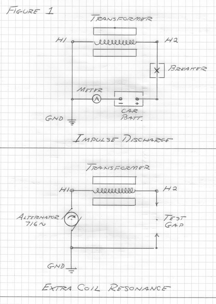
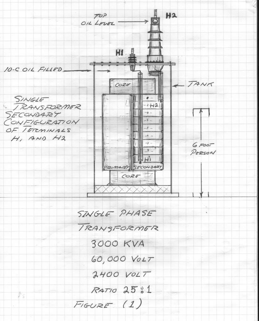
        Now one transformer is removed from the bank, its 2.4 Kilo-Volt primary will remain unused. The secondary coil is asymmetrical for grounded neutral connection. Hence the secondary coil has a high voltage bushing for line connection, and a distribution voltage bushing for neutral connection. See Figure (1). This is an "odd order series" winding, or a "quarter wave" type configuration.

        This single phase power transformer has the following specifications:
        Full Load Capacity: 3000 KiloVolt - Amperes
        Secondary Voltage: 60 KiloVolts
        Basic Impulse Level: 300 KiloVolts

        Measurements on the secondary windings give the following results:
        D.C. Winding Resistance: 24 Ohms
        60 cycle Winding Reactance: 60 KiloOhm

        Hence the Inductance is derived as: 160 Henry

        And the ratio of reactance to resistance of this winding is derived as:
        2500 Numeric


        .....
        Originally posted by T-rex
        60 KV Transformer, Final

        (1) Given in the previous transmissions is that there exists three distinct modes in which this transformer can operate.

        I) As a power transformer for machine frequencies. The inductance is space scalar and the dielectric energy content is negligible.

        II) As a resonant transformer for VLF frequencies. The inductance is a sine function of space and a considerable quantity of dielectric energy content exists, equal to the magnetic energy content. The capacitance is now a cosine function of distance. This resonant energy exchange is powered by a loose coupled source of Alternating Current through the primary winding.

        III) As an extra coil for VLF frequencies. Again equal energies in a resonant exchange but now series fed through the neutral to earth connection. The primary coil now is inactive in this operation.

        2) Some further experiments are in order here.

        The DC, or static, resistance of the 60 KV secondary winding is measured to be:
        24 Ohm

        Handy is a car battery:
        12 Volt

        Now connecting the line, H2, terminal to its line vacuum breaker, Figure 1, and connecting the line side of the breaker to the positive terminal of the car battery, a basic current loop is formed.

        The negative terminal of the car battery is connected to an ammeter and then to the transformer neutral. The neutral, H1, is grounded to station ground.

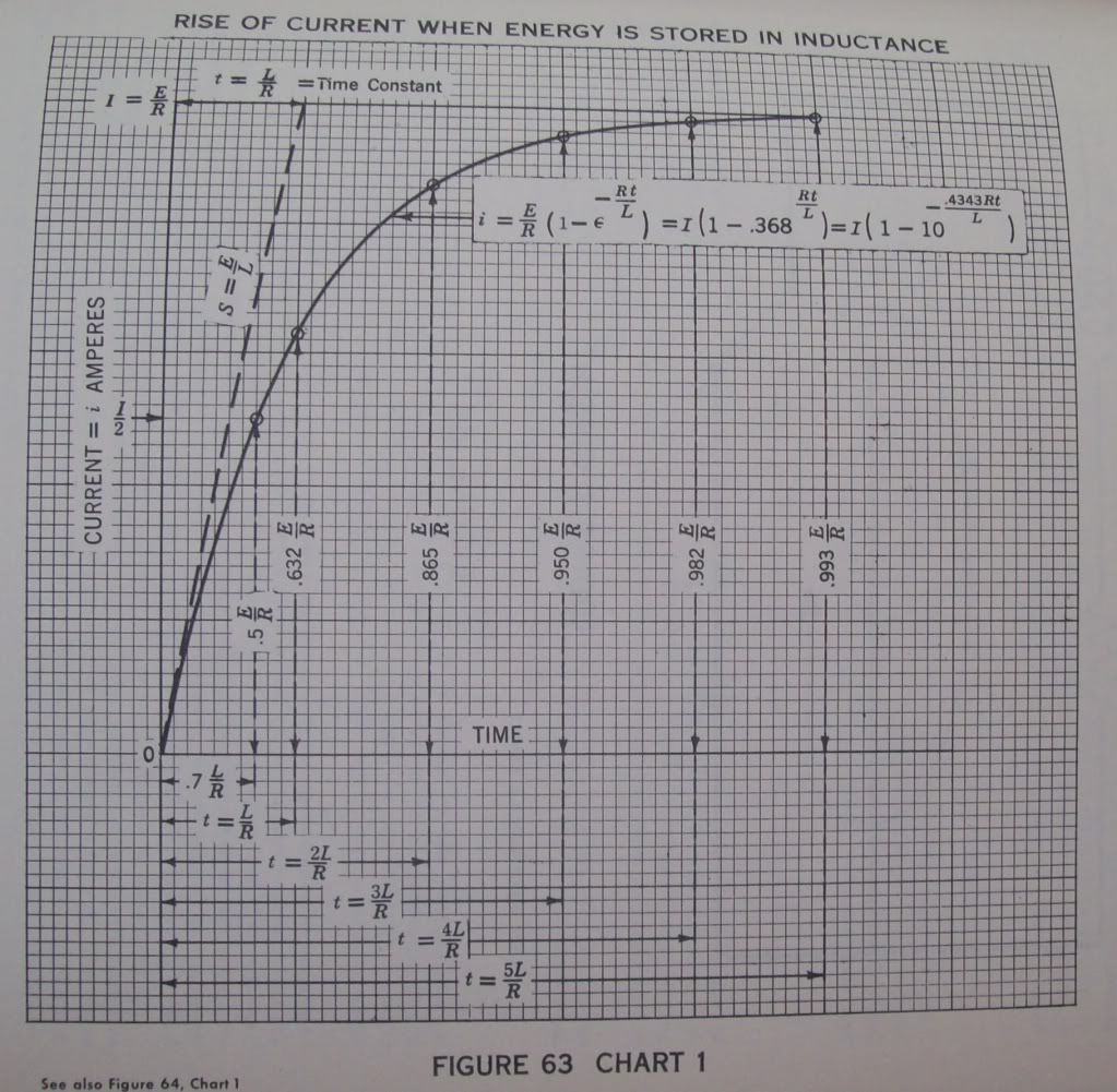
        3) The vacuum breaker is closed completing the current loop, this loop a basic, L,R, circuit of 24 Ohm and 160 Henry. Upon closure a stopwatch counts time from the instant of this closure, T, equals zero. Observing the ammeter it is seen to rise very slowly. At the point when the ammeter reads
        316 milliAmpere

        The stopwatch is checked. The span of time to reach 63.2 percent of the maximum value is called the magnetic time constant, u. The stopwatch reads
        6.7 seconds

        The ammeter continues to climb, in ever smaller increments closer and closer to 500 milliAmp. It is noticed it takes over 33 seconds for the inductance to reach full charge. See figure 63.

        At full charge the winding current is one half Ampere. The static winding inductance is 160 Henry. Hence the magnetic energy storage is derived as
        20 Watt-second

        4) Now the vacuum breaker is tripped, this instantaneously breaking the loop. A streamer several feet long erupts from the line, H2, bushing insto space. Since no escape of energy exists the magnetic energy is abruptly converted into dielectric energy at a fundamental frequency and its odd order harmonics. This was given as
        716 cycles per second

        The effective values of inductance and capacitance were determined to be 100 Henry
        and
        500 picoFarad

        By the law of conservation of energy the magnetic energy equals the dielectric energy. By algebraic operation the ratio of EMF to current is the square root of the ratio of 100 Henry and 500 picoFarad,
        450 Kilo_ohm

        And thus from a 12 Volt car battery the EMF developed at the line terminal, H2, is derived as
        225 KiloVolts peak

        This assuming a sinusoidal waveform. Here the harmonics were burned off in the streamer issuing from H2.

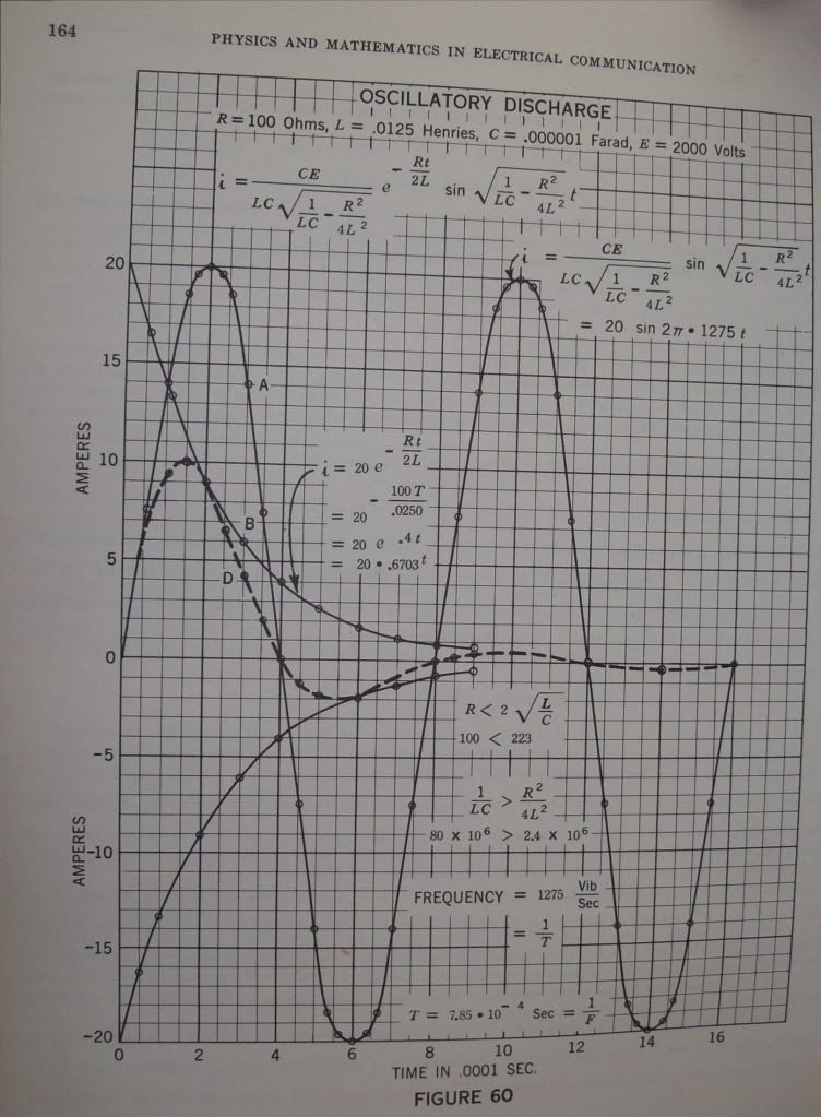
        (5) The increase in frequency from 60 cycle to 716 cycle gives an increase of the effective resistance to 72 Ohm, at 716 cycles per second. The effective inductance is 100 Henry. The reactance of this inductance at the oscillating frequency, Omega,
        4500 radians per second

        is derived to be Omega L or
        450 Kilo-Ohm

        And the time constant of the 716 cycle oscillation is derived from the effective inductance in proportion to the effective resistance, L, over, R. It is however that the oscillatory energy is magnetic only half the time, the other half is dielectric. Hence the time constant is given as one half the ration of inductance to resistance, one half of
        1.39

        Gives the oscillatory time constant as,
        .7 seconds

        At this time the magnitude of the oscillation has diminished to one over Epsilon, or
        36.8 percent

        The oscillation becomes inaudible in about five times this, or,
        3.5 seconds

        See figure 60.

        (6) The magnification factor of this oscillating winding is determined by the ratio of the effective winding reactance to the effective winding resistance,
        450 Kilo-Ohm
        to
        72 Ohm
        Giving
        6250 numeric

        The initial, or peak, current is one half an ampere this the effective value, or per square root of two, is given,
        356 milliAmpere RMS

        The initial, or peak, EMF is given as 225 Kilo-Volt, hence the effective value is,
        159 Kilo-Volt, RMS

        The product of these values gives the total oscillatory activity in the transformer winding,
        56.6 Kilo-Volt-Ampere

        (7) The losses in the windings are given by the square of the effective current times the effective resistance, I squared R, or the Back EMF developed by the losses is the current times the resistance, I, times, R, or

        25.6 Volt

        Here from are derived the basic transformation parameters in the operation of the 60 KV secondary winding as a resonant extra coil, this for an output potential of 160 KV at 716 cycles per second.

        Input (H1) Power Requirement
        9.1 Watt

        Input Impedance, E, over, I, or,
        72 Ohm

        This a resistive load as seen by the source of alternating electric energy. Hence, a 10 watt audio amplifier, on the 50 Ohm output tap, will give rise to a resonant oscillation, building up over a time span of 3.5 seconds, this with an activity of 56.6 KiloVars and an electrostatic potential of 160 KiloVolts. Here established is the concept, -- "Magnification Transformer"

        73 DE N6KPH


        From Perrine's book "Physics and Mathematics in Electrical Communications":


        Last edited by dR-Green; 10-09-2012, 05:33 AM.
        http://www.teslascientific.com/

        "Knowledge is cosmic. It does not evolve or unfold in man. Man unfolds to an awareness of it. He gradually discovers it." - Walter Russell

        "Once men died for Truth, but now Truth dies at the hands of men." - Manly P. Hall

        Comment


        • DR Green, Dr Green...

          dR Green,

          Why bringing "In" such kilo-metric long experiment?
          I mean Why?

          That does NOT bring this analysis any "deeper"...but just brings "Confusion Time".

          Number One, Battery is NOT connected directly to H1 Coil, but to its "Neutral" to H2, that is a "Derivative" to another "open" coil.
          Number Two, the Two final Pic's show Sinusoidal Waves?!

          Seth was asking a very simple question...that does not needs to go into the "Kilo Volts latitude Input" or complex wiring primary- and a hundred secondaries.. Bro...

          Just use a Single Coil, and make it just ONE OHM Resistance, this way it will maintain unaltered I and V...
          And Use a SQUARE WAVE, not a Sine-wave, We are not talking about LC Circuits either, but just a single and simple Coil of Wire...
          Not attached within the same frame core to several coils,...not attached to absolutely NADA...Nothing...a poor and lonely single Coil...

          I really do not understand why you bring such clever experiment to such a simple question as also others simple answers...

          I could only think off two reasons...

          1-To bring confusion to this subject...so we loose interest on this...

          Or

          2- To show OFF, that You are very good at HV and Big Transformers Experiments...

          And out of the two...I am positive it is number two


          Ufopolitics


          P.D:"He who knows, does not speak. He who speaks, does not know." - Lao Tzu

          I tell You dR Green...YOU SPEAK WAY TOO MUCH...
          Last edited by Ufopolitics; 10-09-2012, 06:38 AM.
          Principles for the Development of a Complete Mind: Study the science of art. Study the art of science. Develop your senses- especially learn how to see. Realize that everything connects to everything else.― Leonardo da Vinci

          Comment


          • thanks all

            i did find this picture > here < that also states the coils polarity (whatever it means in this case) is reversed during magnetic field collapse. one wonders how strong the poles are even for a brief time when talking about the large spikes. i guess if the energy in the spikes represent the loss of energy from the magnetic field then the speed of motion of the field collapsing must be rather impressive.
            rapidly moving magnetic fields are i'm sure capable of something
            Last edited by s e t h; 10-09-2012, 07:08 AM.

            Comment


            • Originally posted by Ufopolitics View Post
              dR Green,

              Why bringing "In" such kilo-metric long experiment?
              I mean Why?

              That does NOT bring this analysis any "deeper"...but just brings "Confusion Time".

              Number One, Battery is NOT connected directly to H1 Coil, but to its "Neutral" to H2, that is a "Derivative" to another "open" coil.
              Number Two, the Two final Pic's show Sinusoidal Waves?!

              Seth was asking a very simple question...that does not needs to go into the "Kilo Volts latitude Input" or complex wiring primary- and a hundred secondaries.. Bro...

              Just use a Single Coil, and make it just ONE OHM Resistance, this way it will maintain unaltered I and V...
              And Use a SQUARE WAVE, not a Sine-wave, We are not talking about LC Circuits either, but just a single and simple Coil of Wire...
              Not attached within the same frame core to several coils,...not attached to absolutely NADA...Nothing...a poor and lonely single Coil...

              I really do not understand why you bring such clever experiment to such a simple question as also others simple answers...

              I could only think off two reasons...

              1-To bring confusion to this subject...so we loose interest on this...

              Or

              2- To show OFF, that You are very good at HV and Big Transformers Experiments...

              And out of the two...I am positive it is number two


              Ufopolitics
              If you paid attention then you would see that here also we are dealing with a simple coil of wire, it's in the description, and it's shown in the diagram. The experiment deals with a 12 volt supply charging an inductor over time. The switch is opened, a streamer several feet long breaks out of the coil terminal. 12 volt input, several feet long streamer output. Do you see the connection?

              Also I quoted Eric Dollard's experimental analysis, I'm not showing anything off except my ability to recognise some tiny speck of science on this forum and pass it on to people who ask questions.

              An inductor has inductance and capacitance = LC if there's a variation in a parameter such as voltage, hence the energy exchange between L and C giving rise to a resonant frequency of the given inductor. Besides that, it says

              3) The vacuum breaker is closed completing the current loop, this loop a basic, L,R, circuit of 24 Ohm and 160 Henry
              LR.

              You don't need to protect people from confusion, they might get things that you don't. That's the advantage of multiple people and the point of any collaboration. I'm more confused by your description than I am by Eric's experiments and descriptions. We can read wikipedia and describe things all day long but that doesn't engineer us a working system. You say "make a 1 ohm coil", is the resistance the only important factor to consider in an inductor that's going to be driven at a certain frequency? No coil size or geometry, no capacitance, no inductance, only resistance to consider? Yes certain information may be confusing, so was figuring out 1+1 = 2 at one time in our lives, but suppressing and trying to distract from things that have the potential to confuse only hinders progress.
              Last edited by dR-Green; 10-09-2012, 08:32 AM.
              http://www.teslascientific.com/

              "Knowledge is cosmic. It does not evolve or unfold in man. Man unfolds to an awareness of it. He gradually discovers it." - Walter Russell

              "Once men died for Truth, but now Truth dies at the hands of men." - Manly P. Hall

              Comment


              • Originally posted by s e t h View Post
                can someone explain to me how a dc pulse circuit through a nice coil, for instance, can create voltage spikes many multiples larger than the source voltage?
                i mean the resistance in the coil should be somewhat equivalents, whether voltage is applied or removed, so how does the magnetic field supposedly collapse so rapidly as to create a spike?
                cemf should also be more or less equivalent while building or collapsing the field should it not?
                if someone can explain how a say 12V built field can deliver say a 240v spike from the same coil at initiation of collapse i'd like to hear it please.

                Carroll explained quite well why the voltage produced by a magnetic field
                collapse can be quite high. So i'll give some thoughts on the question below.

                cemf should also be more or less equivalent while building or collapsing the field should it not?
                I don't think the inductance of the discharge path includes the coil that is
                discharging, if not then the inductance of the discharge path means only the
                wire's and load, not the coil itself, and also magnetic fields will be built around
                the current paths in the discharge circuit (wire's and stuff), when the
                discharge current try's to stop that field will collapse to try to maintain
                current but it is small and weak - low inductance and likely has a low
                resistance discharge path and more time to discharge because the initial
                discharge current will likely peter out and not stop suddenly so the field will
                collapse as slowly as the current flow drops.

                Sudden stop of current equals a higher voltage discharge for a given energy,
                coil and discharge resistance, a slowing down of current over time will see
                a lower voltage discharge for the same energy, coil and discharge resistance.
                There are different ways to raise the voltage of the discharge. Rate of
                change of the current through the coil, energy put into the coil, the coil itself
                and the resistance the discharge must overcome to discharge the energy from
                the coil.

                Cheers

                Comment


                • Voltage reversal

                  Hi seth,

                  In the pictures you have posted you see the gray arrows which show the current flowing from the bottom to the top of the coil. This is the traditional view of electron flow which most of us were taught in basic electronics class. As you see in the last picture of the diagram it still shows current trying to flow from the bottom to the top of the coil even after the source has been disconnected. Now if you look at a scope shot you will see what is shown in the last picture. Why does it show that very negative spike if the current was still trying to go the same way? It all depends on your point of view. In the first part of the scope shot where the power is on the scope is showing the top of the coil positive because in relation to the bottom of the coil it is more positive than the bottom of the coil because it is connected to an outside source causing it to be more positive at the top. Now when we remove the outside source the coil becomes the source so to speak. As I said earlier the current wants to continue in the same direction as it was going. Therefore the top of the coil now becomes positive in relation to the bottom because the top has now become the source of electrons because it is trying to keep the current flowing. We see this on a meter or scope as a change in polarity or voltage. But the current is still going the same way. If you were to put a current probe on the scope instead of a voltage probe you would see the current make a quick drop but does not change direction. A dual trace scope with a current probe on one channel and a regular voltage probe on the other channel will show this very clearly. While it appears the voltage changes polarity the current does not.

                  Now if there is a capacitor in parallel with the coil then you would see the coil continue to discharge until the cap absorbed all the energy and then the cap would discharge back into the coil and actually reverse the current and polarity. This charging back and forth between the cap and coil will continue until the total energy is used up. On a scope this is the typical ringing signal you see. I hope this helps some.


                  Originally posted by s e t h View Post
                  thanks all

                  i did find this picture > here < that also states the coils polarity (whatever it means in this case) is reversed during magnetic field collapse. one wonders how strong the poles are even for a brief time when talking about the large spikes. i guess if the energy in the spikes represent the loss of energy from the magnetic field then the speed of motion of the field collapsing must be rather impressive.
                  rapidly moving magnetic fields are i'm sure capable of something
                  Respectfully,
                  Carroll
                  Just because someone disagrees with you does NOT make them your enemy. We can disagree without attacking someone.

                  Comment


                  • Magnet Levitation

                    Hello Seth,

                    Here I am showing a simple test I have conducted on an empty coil (Plexiglass Core)...
                    I tested different magnets, as a Heavy Neo as also my small UFO with a small Neo and secondary fine wire windings connected to two LED (Blue-Red) that will only light up based on Reversed currents to ours...or "spikes" ...

                    [IMG][/IMG]

                    According to both Magnetic Fields positioning (Coil and Magnet) with both aiming North Up, Magnet should not levitate, since North and North/South and South repels...it should not leave the ground at all...but it does.

                    I have made a video of tests...and if you notice Coil Winding is ABOVE Magnet...just like in Diagram, However, it "sucks" it to the exact gravitational center of Coil Magnetic Field...

                    If I reverse magnet it will NOT Levitate...but just vibrates at the very bottom.

                    If I feed Coil linear, with same exact orientation...absolutely nada, nothing will occur...

                    Levitation starts around the 1000-1100 Hertz Frequency...from my oscillator.


                    Regards


                    Ufopolitics
                    Last edited by Ufopolitics; 10-09-2012, 02:48 PM.
                    Principles for the Development of a Complete Mind: Study the science of art. Study the art of science. Develop your senses- especially learn how to see. Realize that everything connects to everything else.― Leonardo da Vinci

                    Comment


                    • Originally posted by Ufopolitics View Post
                      Hello Seth,

                      Here I am showing a simple test I have conducted on an empty coil (Plexiglass Core)...
                      I tested different magnets, as a Heavy Neo as also my small UFO with a small Neo and secondary fine wire windings connected to two LED (Blue-Red) that will only light up based on Reversed currents to ours...or "spikes" ...

                      [IMG][/IMG]

                      According to both Magnetic Fields positioning (Coil and Magnet) with both aiming North Up, Magnet should not levitate, since North and North/South and South repels...it should not leave the ground at all...but it does.

                      I have made a video of tests...and if you notice Coil Winding is ABOVE Magnet...just like in Diagram, However, it "sucks" it to the exact gravitational center of Coil Magnetic Field...

                      If I reverse magnet it will NOT Levitate...but just vibrates at the very bottom.

                      If I feed Coil linear, with same exact orientation...absolutely nada, nothing will occur...

                      Levitation starts around the 1000-1100 Hertz Frequency...from my oscillator.


                      Regards


                      Ufopolitics
                      It looks to me like the magnet when oriented the same way as the coil when the
                      coil is energized the magnetic field produced at the bottom (south) would push
                      the magnet towards the top (north) and the magnetic field at the top (north)
                      would push the magnet towards the bottom (south) the net effect would be to
                      levitate the coil in about the center if the time between the pulses was short enough.
                      If the time is too long the magnet can fall.

                      When oriented the other way the coil south attracts the magnet north and
                      repels the magnet south at the same time, and because the coil south is
                      closer to the magnet than the coil north it overpowers any effect
                      from the coil north on the magnet south.

                      That's how I see it. You would appear to be ignoring the effects of
                      the south pole of the coils magnetic field. The magnet is forced towards the
                      center of the coil in the first instance.

                      Cheers

                      Comment


                      • Perfect sense...

                        Originally posted by Farmhand View Post
                        It looks to me like the magnet when oriented the same way as the coil when the
                        coil is energized the magnetic field produced at the bottom (south) would push
                        the magnet towards the top (north) and the magnetic field at the top (north)
                        would push the magnet towards the bottom (south) the net effect would be to
                        levitate the coil in about the center if the time between the pulses was short enough.
                        If the time is too long the magnet can fall.

                        When oriented the other way the coil south attracts the magnet north and
                        repels the magnet south at the same time, and because the coil south is
                        closer to the magnet than the coil north it overpowers any effect
                        from the coil north on the magnet south.

                        That's how I see it. You would appear to be ignoring the effects of
                        the south pole of the coils magnetic field. The magnet is forced towards the
                        center of the coil in the first instance.

                        Cheers
                        Farmhand,

                        Your explanation makes perfect sense, and I also thought of the same process to be happening...BUT, when I feed Coil linear, absolutely nothing happens, and it should, if it were according to South/Coil attracting North/Magnet til getting center where North/Coil will prevent from magnet ascending-climbing any further...but absolutely nothing happens, and I believe at least it should "jump" to center then fall back...but nope it does not.

                        On the other hand, and I forgot to mention as also to display the circuit, however is noted on video, I am allowing through diodes the flow back from reversed currents and lighting up five CFL's (it is seen on video), IF I disconnect the output flow from reverse currents...magnet collapses to ground...meaning, the reverse flow must be allowed to load the other end, flow out, for the effect to happen.


                        Cheers


                        Ufopolitics
                        Principles for the Development of a Complete Mind: Study the science of art. Study the art of science. Develop your senses- especially learn how to see. Realize that everything connects to everything else.― Leonardo da Vinci

                        Comment


                        • OK fair enough, I can accept that there could more going on than first meets
                          the eye. I can do some tests to see what I think is happening, I cannot argue
                          any points very well without having done the experiment. It wouldn't be fair or
                          right to do that. Still, even if I do the experiment I can only give my
                          unqualified opinion on what I observe. If you observe something different to
                          me then we are bound to give a different explanation. Also please don't see
                          any experiment I might do as being a deliberate attempt to try to denounce
                          you. It does seem like an interesting experiment.

                          I have come to accept that the voltage does indeed reverse polarity, not in
                          the way I envision a polarity reversal, but the bottom of the coil does become
                          more positive than the top, and so is a reversal. Fair enough. Accepted.
                          You're not the only person I've argued that point with though. My idea of a
                          polarity reversal was that the voltage would need to go negative ie, below
                          zero, but both ends stay above zero and remain positive as compared to the
                          circuit ground. It's just the the bottom becomes less negative ( more positive)
                          than the top during the coil discharge. Still I can accept it is a polarity
                          reversal if that is what it is called.

                          Even though I can accept it as such, I still think its just a change of potential
                          not of polarity. If the circuit ground is zero then to me anything above that is
                          positive, to reverse polarity I would have thought a change from positive to
                          negative was necessary. Why not just say, "as the coil discharges the low side
                          of the coil produces a higher potential than the high side". In my opinion the end of the
                          coil still connected to the battery positive is still positive and the bottom of
                          the coil just goes to a higher positive potential. Not to worry. Just a different way to look at
                          it. I intend to do some tests with a series coil element as well.

                          The magnetic reversal I'm not convinced of. But again it may be just a matter
                          of perspective. Anyway I won't promise that I can get any result worth
                          sharing any time soon. I still think that for the coil to reverse magnetic polarity a
                          reversed current must flow through it.

                          Cheers

                          Comment


                          • Hi UFO HI Farmhand

                            I made a small replication of UFO's experiment with levitating magnet.

                            I tried to get the voltage pulse versus the current pulse on the scope.
                            (notice that for sake of clarity, i have inverted the voltage, channel 1, on the scope screen so the flyback spike do not interfer with the current wave).

                            And OK i have to make my homework deeper because, from this experiment, it seems that the magnetic flux Does invert at the end of the pulse. Or the magnet should be propelled out of the coil, or fall out when i reverse the coil with the magnet floating in the middle.

                            And ofcourse what is creating this inversion of the magnetric flux, or is there an other explanation.

                            Thank's

                            good luck at all

                            Laurent

                            UFO levitating magnet - YouTube

                            Comment


                            • Well it works for me with DC through a resistor, with no pulsing. I think I can be
                              sure there is no magnetic field reversal with DC.

                              My observations tell me it is working how I described in my post above.

                              The reason the magnet doesn't keep going is because it is being held in place by repulsion from above and below, as far as I can tell.

                              I'll make a video to show some things. And explain what I'm seeing.

                              Woopy can you try to levitate the magnet using DC and a high wattage resistor.
                              I'm using a large coil though and a few Ohms resistance.

                              Cheers

                              Comment


                              • Hi Farmhand

                                yes i have tried right now the DC experiment.

                                I connected the about same diameter coil with much more winding directly to the 12 volt battery and the magnet levitate and stuck in the middle , same as per my video but very sharply.(did not measure the amperage)

                                So your explanation that the magnet has not enough time to fall from the fast pulsating sandwitch magnetic field , which can be seen as per a sliced DC , seems very relevant.

                                Or can it be that the magnetic field has no time enough to completely collapse ? Does the magnetic field (flux ) has inertial properties ?

                                Just for info i have tried up to 70kHz., and it works also, and very smoothly.

                                Perhaps nothing very special in this experiment, but very interesting to feel the difference in the smooth action of this levitation with pulsed current versus DC .

                                UFO is the term linear relative to DC ?

                                Anyway some thinking experiment ,hope this helps

                                Laurent

                                Comment

                                Working...
                                X