Announcement

Collapse
No announcement yet.

Open discussion for projects on this forum.

Collapse
X
 
  • Filter
  • Time
  • Show
Clear All
new posts

  • short switches and send power to the dump

    Thanks Carroll for the reply and interest in my efforts. One of the other reasons the cap switching commutator was never finnished was, I realised that I needed individual pressure control on each brush, and the way I built the brush towers, they were all glued together so one adjustment for each tower.

    If I had thought about it some more, and given it more tries, I could have come up with a workable solution. But life has a way of taking your steering wheel away from you and handing you back your plans in a dust bin.

    Artv, My system was so much easier to work on, being it was an outrunner, so I could have acess to all the windings, and brushes / commutator sections outside of the generating and housing area. I also drove the gen with a Rotoverter motor, which meant I wasn't dealing with motoring the windings and then switching them out for generation / shorting. That may be a way to configure your switching needs, as I had total phase control (where in the waveform I wanted to short), duty cycle per short (how wide of a time slice the short lasted) and each phase separately controlled from each other - all on the fly while the unit was running. I can see that for motoring and then generating and then shorting then switching for serial / parallel cap dumping, that would get complex in a hurry. - especially if it was a typical dc brushed motor.
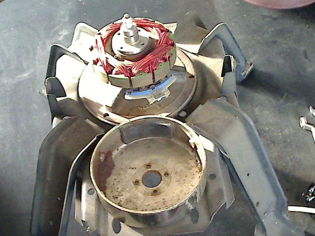

    This is one of the outrunner motors. This one had some magnet damage, and only has one original magnet left.
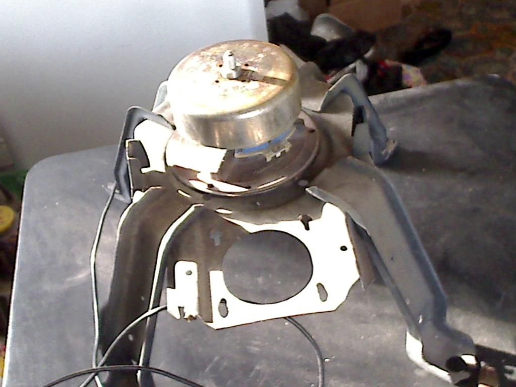
    Here it is with the outrunner bell on:
    Last edited by kenssurplus; 06-30-2015, 11:06 PM.

    Comment


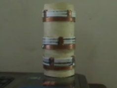
    • This is my coil shorting commutator after being run though shorting tests. You can see the plasma marks from the brushes on the teflon plastic insulator sections.


      Really about the only way I can think of to use a conventional dc brushed motor and adapt more brushes and affect control positioning of those brushes is to convert it into an outrunner by drilling out the shaft, running all coil leads through the shaft hole to the outside. Mount the shaft stationary and spin the outside case. Lotta work though.

      I have some more outrunner motors if you are interested in playing with that topology.

      Comment


      • Originally posted by kenssurplus View Post
        This is my coil shorting commutator after being run though shorting tests. You can see the plasma marks from the brushes on the teflon plastic insulator sections.


        Really about the only way I can think of to use a conventional dc brushed motor and adapt more brushes and affect control positioning of those brushes is to convert it into an outrunner by drilling out the shaft, running all coil leads through the shaft hole to the outside. Mount the shaft stationary and spin the outside case. Lotta work though.

        I have some more outrunner motors if you are interested in playing with that topology.

        You do not have to short directly, you can also just reverse the coil and allow the coils to short to source, No Plasma, charge stays in the system.

        Matt
        Last edited by Matthew Jones; 07-02-2015, 10:08 AM.

        Comment


        • Universal solution for problems concerning many claimed "free energy" devices:

          http://www.teslascientific.com/

          "Knowledge is cosmic. It does not evolve or unfold in man. Man unfolds to an awareness of it. He gradually discovers it." - Walter Russell

          "Once men died for Truth, but now Truth dies at the hands of men." - Manly P. Hall

          Comment


          • hi all. while your on the subject of motors check out these 2 short vids of what i believe aaron, john and peter have been working on quietly together. these are 2 zero force motors if your not familiar.

            https://www.youtube.com/watch?v=YPUajezZUng

            https://www.youtube.com/watch?v=3kpDMMcNQxc

            i haven't built anything like this, but clearly they are mounting stator magnetic fields at right angles to normal and reducing, if not minimizing lenz effects in these prototypes .
            recently i discovered you can use led timing lights to indicate or sense peak or near peak voltage in a parallel tank circuit. i got a joule thief circuit running with a cap across the primary coil. pic 1. both it and the sec winding form the air cored search coil. but i doubt that a blocking oscillator just happens to provide efficient running of a simple tank circuit.so i think i can achieve stronger resonance for less milliamps input with a better strategy for maintaining oscillations.
            another goal with an analogue metal detector is to make it oscillate the search coil with a nice clean sine wave in an effort to reduce losses to multiple harmonic frequencies. presumably the more eddy currents in a metal target circulating at the fundamental freq., the better the response for stronger detection.
            there are several ways to look at this. 1 think of pushing a kid on a swing. you push just after the change of direction to build up momentum,inertia,travel and height. 2 a solar pendulum flower pot toy senses bottom dead centre and fires a pulse to accelerate the magnet at the bottom of the pendulum with repulsion in alternating directions.
            3 then there is parametric excitation,which is like getting yourself up to speed and height on a swing when there is no-one to push you.you can lean backwards and forwards, shift the centre of gravity at 1 or both points of max travel and build up your oscillations.
            i'm thinking topping up the cap voltage, right on both peaks,with a short or limited pulse, of the appropriate polarity through every cycle, is 1 way to maintain strong resonance with low consumption, due to maxed impedance.
            so does anyone know of a circuit that could trigger these top-up pulses at the best timing, possibly using my led peak detectors for timing sensors. i think something like a one shot multivibrator or 2 is what i need.maybe an adaptation of the pulsing circuit in my first post here. without a scope i'm guessing in a lot of ways, but i can tell when harmonic frequencies are quiet on an am radio held close. most of my experimenting is in the 13-20 khz range. pic 2 is a neat colpitts osc. that makes a nice sine wave at 500 k-1 mhz depending on the search coil size and turns, but it only draws 1.2 ma on a 961khz coil i made.it's a strange looking circuit, but very efficient. hard to soup up tho. as a metal detector it has good sensitivity in free air, but by all accounts mid to high audio frequencies give the best ground penetration. so i tune the tank circuit to get down into that range with these circuits.
            i know there are other proper sine wave oscillators like pic 2 on the net. i just want to explore some alternative concepts.
            cheers.
            Attached Files
            Last edited by voltan; 07-13-2015, 01:15 AM.

            Comment


            • hi all. i was surprised to find an old circuit that uses a pigtail neon to generate a sawtooth wave. i will try putting the search coil in series with the neon. maybe a cap across the coil, a tank circuit in series with the neon. ionisation/de limits frequency to about 20 khz. it would need a supply capable of up to 100v. R is a very high value, so a joule thief on the front end might power it ok.
              could be interesting to play with.
              *** i got this to run. with R 1 meg, C 681/680p it makes a tone at about 11 khz in my headphones, with the search coil in series with the neon. the j.t can maintain the oscillation with as little as 2 ma at about 7v input. it's a small signal and it's a bit unstable, but not bad for it's simplicity.
              early testing as a metal detector showed a much increased sensitivity to local capacitance. eg. moving a hand near any part of the circuit, but sensitivity to eddy currents in a metal sample changing the search coil's inductance is what i'm after. wihout the coil the neon is R C timed. with the search coil it has a weak response to metal objects,(running on flea power at this stage tho.), so L has some effect on the resonant frequency. i think making R variable is worth a try.maybe i can improve the sensitivity to inductance changes if i try swapping some components around.
              later testing with a variable 1 meg resistor and a 2.5 uf film cap across the coil showed comparable sensitivity to metal objects to the other circuits i have tried.lotsa harmonics on the a.m band tho.
              i guess a xenon flash tube could function like this with lotsa volts and the right R C values. could make a nice display piece if it doesn't run hot.maybe apply uv output shielding.
              imo this is a great article.
              https://en.wikipedia.org/wiki/Pearso...93Anson_effect

              cheers.
              Attached Files
              Last edited by voltan; 07-08-2015, 09:37 PM.

              Comment


              • hi again. i was even more surprised to find that this oscillates after a momentary push button starts it. pic 1
                pic 2 much improved version.

                cheers.
                Attached Files
                Last edited by voltan; 07-20-2015, 05:03 AM.

                Comment


                • Hi voltan,

                  Your posts about using neon bulbs as oscillators brings back old memories. Back in the 1950's you could buy a "B" battery. It was a rectangular battery that put out 70 volts. It was used to power portable tube type radios before transistor radios became common. My dad had a TV repair shop and liked to tinker with electronics also. He built a small circuit right on top of a B battery with 3 neon bulbs and some caps and resistors. It was basically a relaxation oscillator times 3. The neon bulbs would fire randomly and so it would sit there and just blink on and off. It used such a small amount of current that it ran continually for several months before the battery ran down. He used neons that fired at 55 volts if I remember correctly.

                  Thanks for contributing to the thread.
                  Carroll
                  Just because someone disagrees with you does NOT make them your enemy. We can disagree without attacking someone.

                  Comment


                  • Hi Voltan,

                    In your 2nd schematic the collectors of the transistors cannot receive battery voltage through the capacitive divider. In the first schematic the center tap (or the common point) of the two coils can insure it.
                    One more issue: in none of the schematics are the DC bias voltages provided, this involves the start up of the oscillators will be casual or impossible.

                    Gyula
                    Last edited by gyula; 07-15-2015, 10:47 PM.

                    Comment


                    • Hi Voltan,

                      Okay on the piezo starter for the oscillators, neat idea.
                      Regarding the differing frequencies at the base and the collector, I suppose what you measure at the tank LC circuit (collectors) is what the actual oscillating freq is and a freq meter may be fooled at the base where there may be no clean and close to sinusoid waveforms and these can trigger the counter gate inside the meter twice.
                      But this could be checked by an oscilloscope or by using a very light coupling between the input of the freq counter and the circuit measuring point. Depending on the input sensitivity and impedance of the meter, try to use a series coupling capacitor of say 100pF as a start to check the frequencies again and if you get again the double freq at the base then try to use even less value coupling cap.
                      A choke coil is normally inserted in the wire of the supply voltage that leads to the center tap of the tank coil.
                      In your second schematic the collectors still cannot receive DC supply voltage via the capacitive dividers, you surely know that.

                      Gyula

                      Comment


                      • thanks again gyula. i have deleted a few posts including the dud schematic. i haven't found another osc. circuit on the net, that uses an iso trafo for feedback. so far pic 1 is about as close as it gets. not a bad looking scheme. i would like a scheme with 1 winding in the tank inductor, that delivers the same result, if it's possible.
                        * i just found pic 2 on the talking electronics site. it looks like a flea power circuit. maybe it can be beefed up.
                        cheers.
                        Attached Files
                        Last edited by voltan; 07-20-2015, 05:14 AM.

                        Comment


                        • Hi Voltan,

                          Your desire to have one winding in the tank is possible but to extract energy you have to find some impedance matching means to a load or to another circuit, and such matching can easierly be done by tinkering of the number of turns of a coupling coil to sniff the energy out from the tank. Even so you may lose half of the power when a power match is achieved, unfortunately. (power match happens when your load impedance equals to that of the output impedance of the oscillator, you surely know this)

                          I can see you found a push-pull oscillator which works like an astable RC oscillator of course except that the R components in the collectors are replaced by a coil or coils.
                          You can find many schematics by the way by using google Pictures with key words like 'push pull oscillator circuits'. Already wanted to show this link,
                          Oscillators - part 4
                          scroll down to circuit 21.Push-pull LC oscillator. (there are some other interesting circuits there)

                          For pic 2 circuit the power level can be increased by biasing the transistors to higher current with the base bias resistors but the limit is frequency stability.
                          If you have access to a junk AM pocket radio of the 70s, they used audio output transformers in their push-pull audio amplifier, you could use such here for the center tapped coil. But then it would not be a single coil tank...

                          It is always good to vary the DC supply voltage for such oscillators, it is easier to find the best oscillation conditions, output etc. IF you have not got a variable DC supply, you could connect some AA batteries in series to have a few voltage values available in 1.2 or 1.5V steps.

                          Gyula

                          Comment


                          • cheers mate. i'm playing with different oscillator schemes with the aim of developing simple but effective metal detector circuitry. the tank coil is the search coil. i'm not trying to extract any power from it, at this stage, but the output of the ferrite bead cored pickup coil i call a meter probe is more than i would expect, given the scale of the 2 coils. i lost my camera privileges. i'll make a scribble of it. see scribble. a continuous spiral core, maybe with an air gap, all the way around the search coil or ring cores instead of a spiral for a more ideal right angle could be interesting. hard stuff to engineer tho. i haven't checked it out properly and inside the search coil and outside are 2 different magnetic environments. thanks for the link and yeah google images has been very helpful at times.
                            * # 26 in that link. ground penetrating radar. now your talkin.
                            cheers again.
                            Attached Files
                            Last edited by voltan; 07-20-2015, 09:47 AM.

                            Comment


                            • Hi Voltan,

                              So it is about metal detectors, ok. I recall an interesting-looking offer in ebay, though the schematic could be guessed only from his site: http://bscircuitdesigns.com/ You may be familiar with the BFO (Beat Frequency Oscillator) type detectors where two oscillators with identical or almost identical frequencies are mixed and the frequency difference falls in the low audio range when one of the two oscillators are detuned (by say a metal object). See his second youtube video on the BFO demo: https://www.youtube.com/watch?v=ZO8bU6KtEk4
                              The circuit involves a microcontroller too, the codes are available from him if someone buys his ebay offer. His postage cost is too high though.

                              Such type of BFO based metal detectors are probably available on ebay from other sellers, though I guess you prefer testing and building such circuits. Nevertheless, ideas are good to see from others.

                              Greetings, Gyula

                              Comment


                              • hi gyula. the first detectors were b.f.o. technology has moved on, but i want to see if i can come up with something to improve the performance, and yeah, i like the idea of designing and building my own.
                                i just had a thought this morning. some car cd player manufacturers a while back developed anti skip using a delay loop of 2 or 10 seconds, not sure which. if the car hit a bump it cut out the messy bit and replaced it with another clean sample off the cd. all before you heard it. something like that could constantly compare the search coil freq. with what it was 5-10 secs. ago. this could replace the steady reference osc. and hopefully give it some immunity from wet beach sand or mineralised soil causing false detections, which needs sophisticated circuitry to manage, known as ground balance, in conventional analogue detectors. apart from making opto-isolators work i have zero experience with digital stuff tho. i can't think of an analogue way to do that, short of incorporating a cassette player with a loop of tape ! any suggestions anyone. is there a 10 second time delay audio freq. device or module out there? can a digital voice recorder be adapted or modified?
                                *i see things like hallmark novelty cards and other low budget digital audio diy stuff, that can record over and over. with 2 of these and some 555 timing, or similar, i could record on #1 for 10 secs while playing #2 at the same time, then swap roles. not so simple but the benefits could be worth the complexity.
                                pic 2 is an improved osc. circuit. the diode drop under vr1 is .6 v. t1 is a bc547. for 8.8 v input @ 5 ma the probe caps are perfectly balanced with a total of 2.8 v. at 6.8 v cranking vr1 up to 10 ma gives a slightly unbalanced 2.8v on the probe, and it's self starting if i turn vr1 towards the + rail.best to add say a 1k above vr1 to avoid a near short condition if it's turned right up.
                                Mr Quantsuff, i salute you.
                                ** I didn't know there are diy scope kits out there for $20-60+shipping.the kit in the pic comes with all the smd stuff mounted and soldered. there's a handful of regular components to add yourself. $49 at jyetech.com. good reviews and good value.

                                cheers.
                                Attached Files
                                Last edited by voltan; 07-23-2015, 07:58 PM.

                                Comment

                                Working...
                                X