If this is your first visit, be sure to
check out the FAQ by clicking the
link above. You may have to register
before you can post: click the register link above to proceed. To start viewing messages,
select the forum that you want to visit from the selection below.
Announcement
Collapse
No announcement yet.
Mikhail Dmitriyev - Input 1000 W, Output near 3000 W.
Yes the Arduino board has (depending on the model) a number of analog I/O lines and digital I/O lines. For example here is a quote from the arduino website:
"The Arduino Mega 2560 is a microcontroller board based on the ATmega2560 (datasheet). It has 54 digital input/output pins (of which 14 can be used as PWM outputs), 16 analog inputs, 4 UARTs (hardware serial ports), a 16 MHz crystal oscillator, a USB connection, a power jack, an ICSP header, and a reset button. It contains everything needed to support the microcontroller; simply connect it to a computer with a USB cable or power it with a AC-to-DC adapter or battery to get started. The Mega is compatible with most shields designed for the Arduino Duemilanove or Diecimila."
Because it has a clock speed of 16 mhz I would be fairly certain that it would be fast enough to read a hall or optointerrupter or any other position sensor and to fire an associated H-bridge. I believe there are some people using a setup like this to run a bedini pulse motor / generator.
I found a arduino mega 2560 clone board for about $18 US.
Hope this helps,
Ken
Yes 16Mhz is fast enough, I used an 8Mhz Atmega to run this muller motor. (well, two of them)
I like the simplicity of this, but i think the output would be erratic if all pieces were not made exactly the same. It is basically the same concept used in mass manufactured bearings. With the right jigs, you could probably make many of these quickly and cheaply.
Just a thought,
Greg(gdez)
I have heard a little about arduino and like what I have seen. After watching purely primitives last vid with the use of the mercury switch, I think that these controllers would work great for these type of projects. Being able to adjust the speeds with pwm's, or vfd's would make the experimenting much easier and also let you tune the particular machine you are working with. Also in some of my chaotic pendulum experiments I have found that sometimes you don't even need a push, you just need a stop or a slow down, at the right time. It would be interesting to take something like drak's muller motor replication and add some imbalance to it. Could coils act as springs ?
just some more thoughts and good luck to all
Greg(gdez)
I can see what you are saying guys about controlling a motor/s.
The weights can be positioned in the right place for optimum torque at all times.
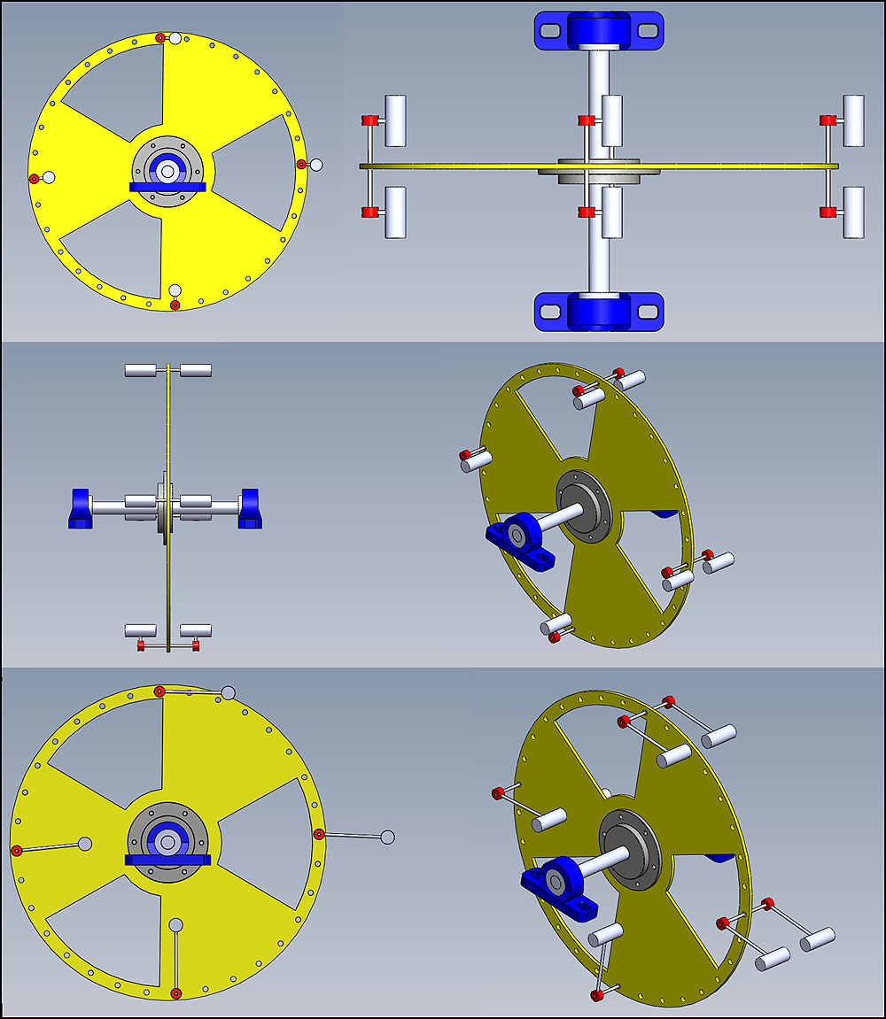
I have been playing with the 1:3 scale Mikhail replica in Solidworks.
This is what I am building first as I have doubts about whether simulation simulation software can provide true feedback and playing with a full size version is not financially viable.
My research shows me 1:3 scale is the smallest possible with off the shelf components and after I saw the new bearings I wouldn't want to try any smaller.
The hub is excellent and was actually manufactured by SKF not Challenge. I'm very impressed with it. Apparently on "Gates"' youtube advert taperlock bushes are a 60 year old technology.
I think using the woodruff key is well over the top at this stage.
I didn't just buy the bolt on hub because it was an off the shelf item. I know I can reuse it to scale the model up should that option become available. I'm fairly certain it would run 200 foot pound of torque carrying at least 300kg.
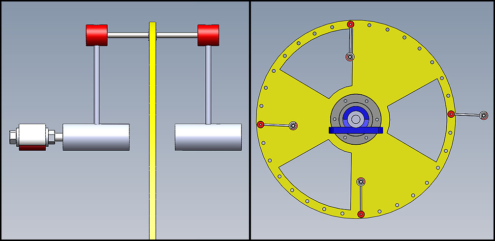
Here are some of the experiments I want to try first.
I have also received the wooden frame from my friend, which I will be adding to the drawings.
I have measured the bearings and decided that a 5mm sheet would be much better. This means I can use aluminium as 5mm sheet is far cheaper than 6mm.
This is where the element magnets should be fixed I believe for optimum deflection. 45 degrees to the 12 o'clock position.
The optimum deflector/s position/s will have to be experimented with.
If the short version works, then I wondered whether a longer version could work too, just to see the difference in rotation speed / torque output.
I strongly believe that it is simply the wheel having more weight on one side that provides the key to gravity being able to assist in producing the extra energy.
The other thing I believe is that it isn't just the frequency of 32 that will work.
I believe it is the torque curve that allows torque to be used and 32 deflecting elements is like having a torque curve of a 32 cylinder engine.
At some stage I would like to prove if; a certain amount of weight can be manipulated into the right postions, with the correct timing and having a torque curve smoother than 32 elements being mechanically deflected, then can the device can work with less elements.
I had a little brain wave this evening about the non deflecting element version.
The big wheel with the weights having a sprocket driving a smaller wheel with the magnet running a ratio of 1:4.
This would place the diametrically magnetized magnet in perfect place for maximum deflection 4 times for every 1 turn of main wheel.
It gets rid of the need for a super fast linear actuator and potentially an input power.
Self perpetuating?
Would it stop or carry on to destruction?
I had a vision of it going into silly rpm and blowing up in the garage and smashing apart.
Can anyone else see my vision or am I just talking codswallop?
I sent off CAD drawings to at least 10 companies for the deflecting element parts that need turning.
I wonder how everyone elses experiments are getting on?
I strongly believe that it is simply the wheel having more weight on one side that provides the key to gravity being able to assist in producing the extra energy.
The other thing I believe is that it isn't just the frequency of 32 that will work.
Yes, I agree completely. I've felt this way for a while. This is, at its simplest, a powered over-balanced wheel. Any design that achieves over-balance with a small amount of additional power should work.
I had a little brain wave this evening about the non deflecting element version.
The big wheel with the weights having a sprocket driving a smaller wheel with the magnet running a ratio of 1:4.
This would place the diametrically magnetized magnet in perfect place for maximum deflection 4 times for every 1 turn of main wheel.
It gets rid of the need for a super fast linear actuator and potentially an input power.
Self perpetuating?
Would it stop or carry on to destruction?
I had a vision of it going into silly rpm and blowing up in the garage and smashing apart.
Can anyone else see my vision or am I just talking codswallop?
If I understand correctly, you would have to calculate the proper gearing so that the 2 rotating diameters lined up properly at the correct times but yes, that would seem to work fine.
I wonder how everyone elses experiments are getting on?
I completed the version I was working on where I reversed the motor rotation but the results were disappointing. I needed a hard stop to catch the weight prior to reversal and ended up cracking the main arm from the impact. My next move will be to eliminate the stop all together and attempt to control a continuous forward rotation with a microswitch and slip ring timing.
I completed the version I was working on where I reversed the motor rotation but the results were disappointing. I needed a hard stop to catch the weight prior to reversal and ended up cracking the main arm from the impact. My next move will be to eliminate the stop all together and attempt to control a continuous forward rotation with a microswitch and slip ring timing.
Regards,
Charlie
Sorry to hear you are having mash ups.
I've been thinking about your design.
3 motors 120 degrees apart or 4 motors 90 degrees apart. Can bus connections. This way only one set of slip rings needed for 3 or 4 motors.
Just a thought.
Any of these builds involving weight and steel ain't cheap though.
Replicator 1 is also having problems too.
Having the extra weight bent one of the shafts after it was deflected by the kicker wheel.
I seems like 8mm mild steel for the deflecting element shafts is too weak for anything much over 0.5kg per element.
He has brought some hardened 8mm shafts but they are too difficult to drill.
So without a complete rebuild it looks like it isn't going to work due to weakness of the mild steel shafts.
I received my 4 x 4mm grade 5 titanium shafts today and I'm very impressed by the strength and weight properties.
I hung a large sauce pan that weights nearly 2 kilos and swung it around without any flexing.
It is very difficult to make them flex by hand.
They will certainly do the job.
I have a machinist in UK onboard now making up the first 4 deflecting elements.
Fingers crossed I will have a perpetual motion machine for Christmas!
I like that link you posted Gdez. Very simple and effective.
For some reason it reminded me how rubbish the UK military SA80 is compared to an AK47. I think it was the part when he puts sand in and it still works!
Maybe this is how they did stuff like this 100's of years ago. I wonder if Bessler was using any such advantages, as the shops were a little low on one way bearings back then!
3 motors 120 degrees apart or 4 motors 90 degrees apart. Can bus connections. This way only one set of slip rings needed for 3 or 4 motors.
Just a thought.
I am beginning to wonder if we are the only ones left reading this thread...
Yes, I'm thinking of ultimately using 3 weight/motor combinations. But the number of slip rings tends to grow with more motors unless you can suggest a simpler way? What I am doing right now for the single motor build is splitting the positive lead into (2) 180 degree slip ring segments. Each of these segments is wired to a connector of a single NO/NC momentary switch and using the common as the output to the motor. A cam (tied to the rotating arm) switches the 2 inputs. Sounds more complicated than it is. Just picture 2 switches in series. One is activated by the location of the main arm and the other by the location of the rotating weight arm
But to add more motors makes it more complicated. I could split the slip rings segments into 3rd's but then I may not have enough length of slip ring for the motor to fully rotate. If you can suggest a simpler way, please let me know.
Regards,
Charlie
Hi Again Charlie, All,
If you mount the (say Arduino) motor controller to the main wheel, then there would be only the need of one slipring set (for dc power as the controller board can use this same source also). Or to avoid sliprings altogether and have it a self powered wheel, then you would need to place air core coils somewhere on the disk and external magnets to generate your controller and motor supply by the rotation of the wheel.
By using an Arduino with a wireless interface, you could adjust the timing, dwell, motor speed (PWM),etc, while the machine is running.
You guys are right of course. However, one of my main goals has always been to create something that was simple enough for anyone to build. I'm thinking of course of folks who don't have easy access to electronics like we do. Even Mikhail's design is mainly mechanical with the exception of the motor/generator.
I've recently done several tests on a couple of ideas that didn't work out as expected. I'm rebuilding right now and discovered that the motor gear has been slipping all this time and apparently the reason why my other ideas failed!!!! Aarrggghhhh.....
Welcome to the club! lol
On the remote control of several motors you don't need to go to an Arduino, stay with IR remote control, for example:
4 channel IR remote control Relay Board - AZ4CR-03
US$16.95
 Tweet
Tweet


Comment