Announcement

Collapse
No announcement yet.

Mikhail Dmitriyev - Input 1000 W, Output near 3000 W.

Collapse
X
 
  • Filter
  • Time
  • Show
Clear All
new posts

  • Update 28th January 2013

    Gravity Wheel Group Project Contributors

    soundiceuk (Paul Townley) £200
    Regster £20
    Drak $15
    Kind US friend $85
    PhysicsProf (Steven Jones) $15
    Swampwalker (John) £45
    Gdez (Greg) $25


    TOTAL PAID INTO GROUP POT £344 (APPROX $543 USD)


    At the moment we have one out of three monitors working. Both laptop batteries are scrap. One laptop charger and a mouse not working.

    The other thing that annoyed me is I paid for a lifetime license of AVS Video Editor back in 2008. Now they have "lost" any record of this and tried to accuse me of running the software on multiple machines.

    Hopefully this will get resolved.

    I'm pretty much out of hard drive space.... it's all a juggling act!


    I'm pretty broke for a few weeks now, so I will get to work on the design upgrades.


    Here are the group replication accounts.
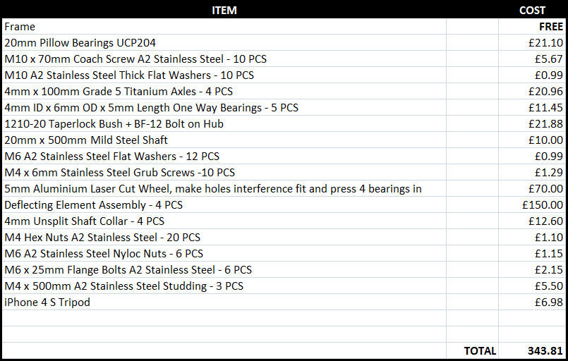


    All the best,

    Paul

    Comment


    • Originally posted by soundiceuk View Post
      Hey, does anyone know where Charlie could obtain any tasty motors like used in these:

      Check out the specifications! Dribble, dribble

      CT6850, 18V Cordless Impact Wrench (U.S.)

      I used to own one of these 18v impact wrenches.

      I snapped a wheel nut with it. It was very powerful.

      They also run off rechargable lithium ion batteries as well as nickel cadmium.

      Cheers,

      Paul
      400 FOOT POUNDS!!!!! Good grief!!! That's insane. (but I wouldn't refuse it if someone gave me one....or two)

      Comment


      • Originally posted by Dusty View Post
        I built a wheel and am testing some of my own ideas. I put a video up Gravity wheel experiment - YouTube , its more less a project in the works.

        I'm not really building exactly what you guys are doing. I'm going to try a ramp, then maybe try some magnet repulsion.

        I'm using 6 mm one-way bearings. I used 6mm precision drill rod I purchased from Fastenal. The rod is inexpensive. I drilled a hole in the end of my mounting bolts and pressed the rod into the bolt. I drilled out the center of a nut and pressed the one-way bearings into that. I welded nuts onto the bigger nut to accept threaded rod. It was all real easy to build.

        You have to be careful not to rotate your one-way bearing assembly too far as the will jam up into the other ones.

        Hi Dusty, hows the replication going?

        Thanks for the heads up on "drill rod".

        I believe this is called "tool steel" in UK.

        All the best,

        Paul

        Comment


        • Update 3rd February 2013

          I have many, many design ideas.

          Of course with a very limited budget, progress can only be made in small steps.

          Here are design upgrades I have planned for the 1:3 scale replication:


          Upgrades:

          Deflecting element axles upgraded from 4mm to 6mm.

          Deflecting element axles length increased from 100mm to 120mm to provide clearance from hub assembly.

          One way bearings upgraded from 4mm ID, 8mm OD x 6mm length to 6mm ID, 10mm OD x 15mm length.

          Aluminium weight hanger shaft holes drilled out from 4mm to 6mm.

          Aluminium weight hangers rethreaded from 4mm to 6mm.

          Weight hanger studding upgraded from 4mm to 6mm.

          Weight hanger studding increased length from 150mm to 190mm for long arm testing.

          Weights drilled and tapped from 4mm to 6mm

          Nuts upgraded from M4 to M6.


          These upgrades will maximize the efficiency using the existing weights.
          Last edited by soundiceuk; 02-03-2013, 03:54 PM.

          Comment


          • This design removes the need to have the bearings pressed into the wheel.

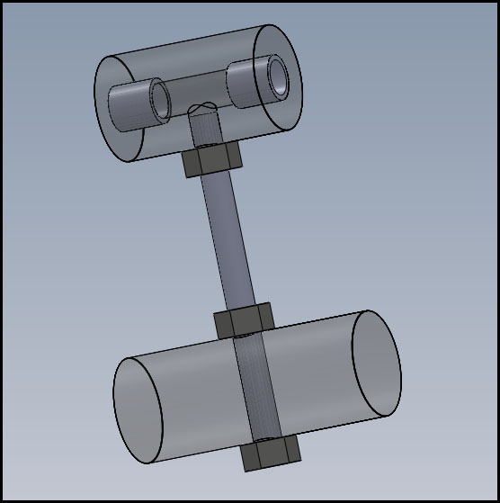
            Two heavy duty one way bearings are pressed into the weight hanger.

            The weight hanger is held in position using two 20mm shaft collars.

            This design can easily be upgraded by using a bigger wheel, multiple wheels, longer arms, bigger weights.


            I have the 20mm stainless steel axle and 20mm shaft collars already but only just over £20 spare at the moment.

            Any contributions to the project will go towards manufacturing these designs.

            Best regards,

            Paul

            Comment


            • I thought now was as good as time as any to resurrect the thread.

              This video demonstrates the forces that the device is using to produce rotation.

              Free energy from gravity, inertia and centrifugal force.

              Max Rotations - YouTube

              If this build can do 19 rotations with one weight. Imagine what one with 4, 8, 16 etc on the same axle could do.

              The weight is 15lbs.

              Best regards,

              Paul

              Comment


              • Thanks for the video and update, Paul
                Pls keep us posted.

                Comment


                • Update 6th June 2013

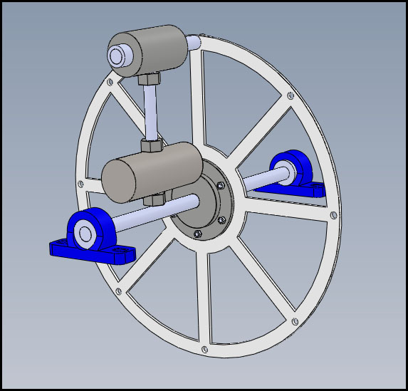
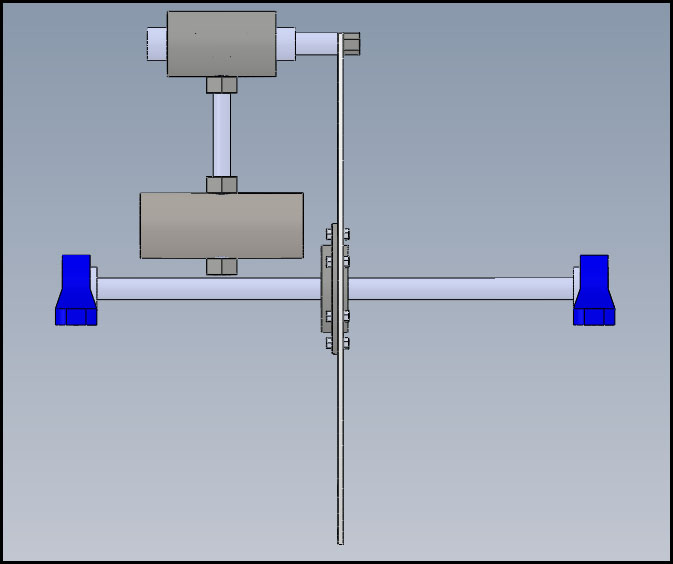
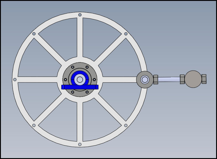
                  Hi folks, things are slowly coming together on the home front so I have been able to hook up my computer with Solidworks and do something.

                  Although the design is not complete I think you may be able to picture my vision.


                  I believe I have ironed out all the bugs that I experienced when running the previous model.

                  - Wobbly weights
                  - Manufacture methods over complicated
                  - Assembly over complicated
                  - Components weak
                  - Vibration issues causing negative oscillations
                  - Poor one way bearings causing backlash
                  - Weights too small

                  Here is the list of modifications:

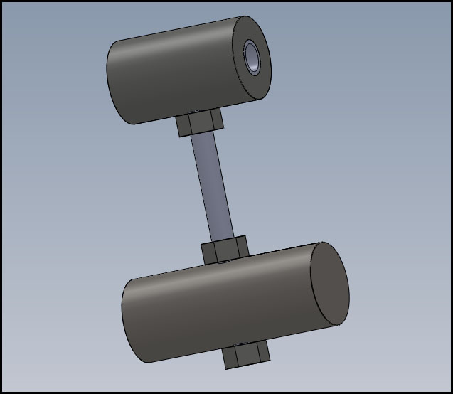
                  1. 20mm stainless steel axle per weight instead of a 4mm titanium axle.

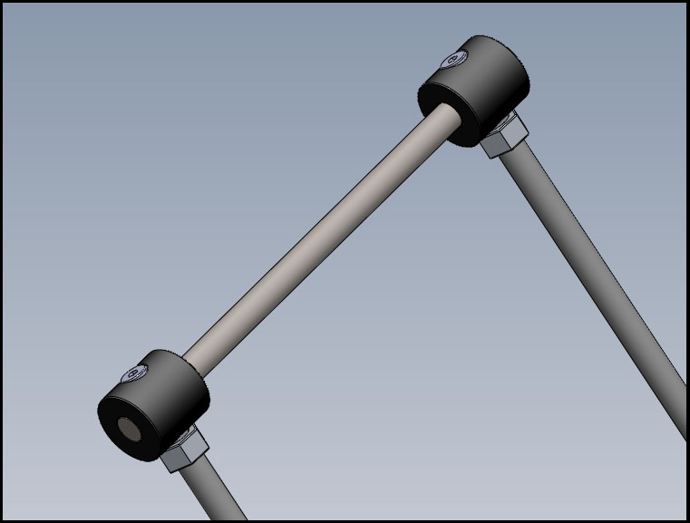
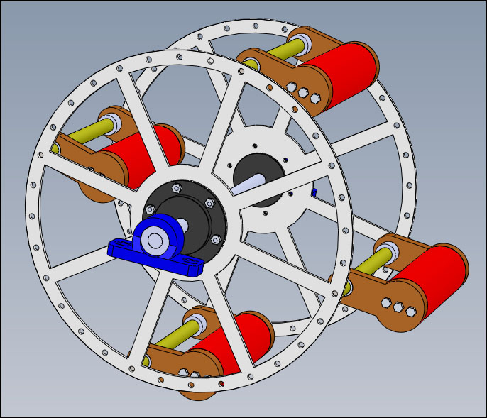
                  2. Two x 16mm thick aluminium arms with three 8mm bolts holding them rigid to the weight each side. This will be quite solid and shouldn't experience the severe vibration that I witnessed on the previous prototype, which I believe is detrimental to the effect we need to achieve for torque amplification.

                  3. One x 20mm ID, 26mm OD x 16mm length one way bearings per aluminium arm.

                  4. Two x 20mm shaft collars mounted internally with 0.5mm gap between the swing arms, set with feeler blades.

                  5. 20mm main axle - which could be easily upgraded by using a larger taper lock bush and bearings.

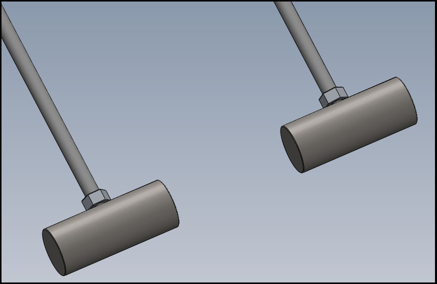
                  6. 70mm x 200mm stainless steel weights. Can be reused if larger arms / bigger wheel is manufactured.

                  7. The 32 holes on the 5mm thick aluminium wheels make the design modular, therefore the longer the main axle the more weights can be added. They can also be connected in series by couplers.

                  8. The swing arm length or the wheel diameters can also be increased to make the design modular.


                  I have very recently met some interesting altruistic engineers that have access to a lot of research funds.

                  The are working on a technology that could easily bolt onto what we are doing as they have a special flywheel that runs in water and stores kinetic energy, it sounds like some sort of Tesla turbine.

                  I don't know all the details but this is looking very promising for our R&D progression.

                  I look forward to building and testing this version soon.

                  The arms will be longer on the prototype, but I've got a little bet on with myself that this design will go down in history as the simplest perpetual motion invention ever.

                  I know the design can be bettered by far. I strongly believe that this could be the device to awake the masses.

                  The more exotic stuff can flow soon after.

                  The public need to see something that they can get their heads around to flip the current paradigm on its head.

                  This is the only way we can move forward as one.

                  We need the secret to be so simple, that once more than 10 know that this technology has the goods then it goes COMPLETELY VIRAL!!!!!


                  The best bit is you don't need a design brief other than knowing that the bigger the components and the higher the frequency of arms the higher the torque amplification.

                  Exact dimensions do not need to be known. You just have to be sensible. This needs a level of precision, but it's really got to be the simplest way to capture 3 energies and put them to use in a clever mechanical way without hiding the secret of what is happening to the naked eye.

                  From my own experiments, you just have to see it and feel it to believe it.


                  What I am going to attempt, finances permitting is show how using a frequency of 1, 2, 4 & 8+ weights does to the torque output on an engine dyno.

                  So you can really see the torque curve on a moving graph.

                  At the end of the day we don't need to see it producing electricity.

                  If it makes torque then that's all that matters before the CAD community can catapult this technology into the next generation of home electricity generation kits and service kits.

                  Best regards,

                  Paul

                  Comment


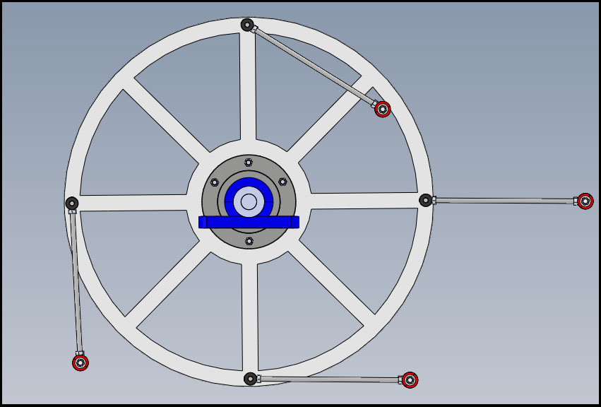
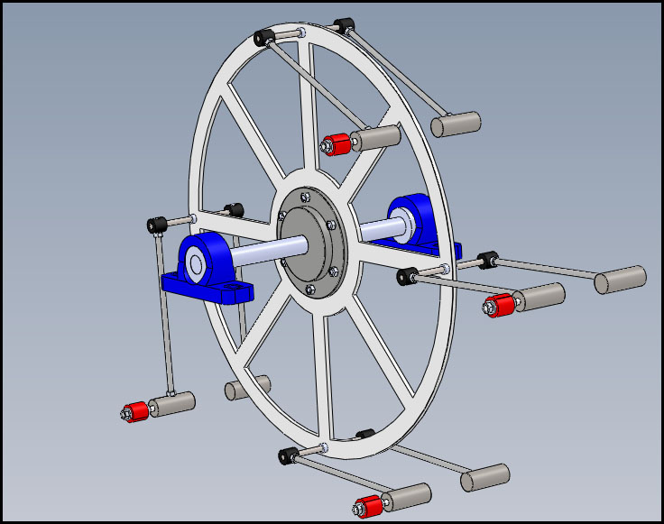
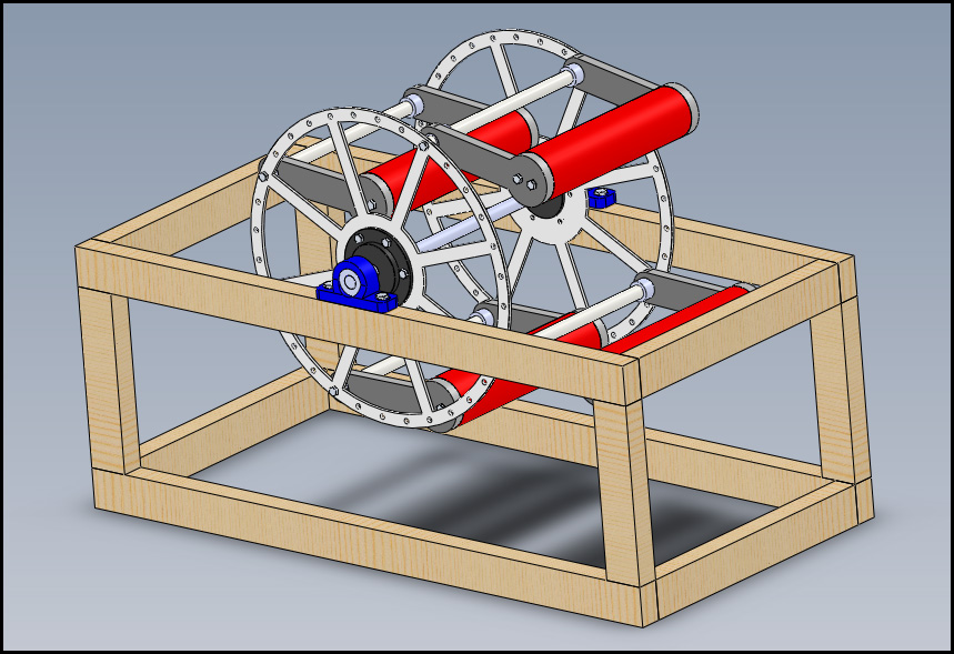
                  • Hi folks, here is almost the final design for prototype 2.


                    The weights are going to be 3" steel bar and weight approx 10kg each.

                    I'm excited to build it.

                    I want to do 1, 2 & 4 weights first before deciding to upgrade the design.

                    I believe this prototype will answer a lot of questions.

                    Best regards,

                    Paul

                    Comment


                    • Hi folks,

                      I have decided to disclose the CAD drawings before disclosing the video.

                      The thing I love about the design is that the dimensions are not critical.

                      Just make it as big as you can with the heaviest weights and largest bearings you can afford.

                      Best regards,

                      Paul

                      Comment


                      • Weights are pressing on fulcrum maybe won't work

                        Comment


                        • Hi Guruji, each weight has two arms, each with a precision one way bearing.

                          Mikhail was using smaller one way bearings successfully to run 6kg weights.

                          Two heavy duty one way bearings will be used for the 10kg weights in my new design.


                          The one way bearings are critical to the operation of the device.

                          The weight pushing on the fulcrum produces leverage and therefore rotation.


                          Best regards,

                          Paul
                          Last edited by soundiceuk; 07-27-2013, 12:27 PM.

                          Comment


                          • Hi folks, it has taken me a while to understand how simply this device works.

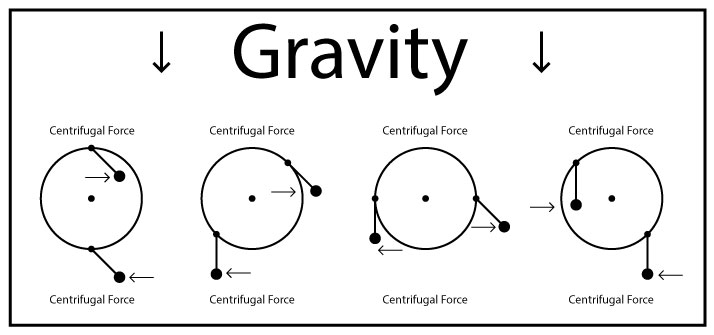
                            I have been sketching this on paper and doing some basic math.


                            If the weight differences can overcome the friction of the main shaft bearings, this diagram shows why I think it will run.

                            Would anyone agree or disagree with the proposed positions assuming the design used one way clutch bearings?

                            I am pondering on how to illustrate the inertia and leverage energies too.

                            Best regards,

                            Paul

                            Comment


                            • Thoughts of a magnet fan

                              Originally posted by RAMSET View Post
                              Dusty
                              IMO,You are one of the great unsung heros of the gravity builds.
                              Thanks for posting your build.

                              This one here is a very interesting one indeed..........

                              When you get a chance if you could give an opinion on this Crazy simple idea over here Perpetual motion?

                              mostly the floatation aspect? {also do you know anything on Burt Rutans Water wheel?]

                              You don't have to comment on that forum,maybe a PM or Email
                              Chetkremens@gmail.com

                              Thx
                              Chet
                              Personally I haven't given gravity wheels much attention but from what I see the general idea is sound.
                              When I see it the water position it looks to be non optimal, while it is relieving some motive resistance surface tension and fresh water weight of the lifting boat.
                              IMHO:
                              1. Mount the boats on one way hinges so the tipping action can help dislodge the boat from the wheel once you...
                              2. Replace the hooks with sliding rods that point straight to the axle, put the boats on the end.
                              3. use magnets (I figured you'd see this one coming.) using magnets to repel the rod from the axle gives more time in the gravitational sweet spot however you may wish to diffuse cogging factor of the repelling magnet by filtering between a thin piece of iron.
                              4. The catch, using a magnet to keep the rod set, then having the wheel turn until the two magnets twist away from each others pull.

                              note on the weight distribution of the boats the heavier it is at the top rim of the boat the better as the closer the weight can to the axis on the upswing and the farther out the overall weight on the tip out. In fact you may wish to bias the mounting of the boat from it's center to near the edge so that it can tip farther and even apply a repulsive magnet at the tip out edge to get a mechanical edge. Come to think of it nylon sheets as rails and polished steel rods might be better than water as they would have lower drag at higher speeds and require less maintenance.
                              Attached Files

                              Comment


                              • OK, screw the magnets

                                Thinking about gravity for a few more hours I realize a simple way of thinking of the problem was that you need one side of the axle to have more downward tork than the other. But, to be stable at full speed you would need more than one axle. 1 a tork axis for the main wheel and a weight axis. In the picture, the pink circle represents the tork axle the thin circle connecting the inner section of rods represents a track guide for pins securing the rods that is the weight axle. The tork axle remains smooth while the weight axle takes the volatile stress. So the heavy bearings wouldn't be needed for the tork axle.

                                Also the weight axle doesn't have to be round as it is a guide track.
                                Attached Files

                                Comment

                                Working...
                                X