Announcement

Collapse
No announcement yet.

Mikhail Dmitriyev - Input 1000 W, Output near 3000 W.

Collapse
X
 
  • Filter
  • Time
  • Show
Clear All
new posts

  • interesting

    Originally posted by purelyprimitives View Post
    Here's my side project looking at alternative ways to rotate the weights. In this video I'm using a mercury switch in an attempt to hold the arm level but as you can see there is still a lot of latency even with this switch. I'm going to try a different rotation scheme for my next version.

    Even though this isn't optimal, an interesting thing is that it is completely scalable. Want more torque...just make the arm longer.

    Comments, criticisms always welcome...

    Dmitriyev Weight Rotation Test 1 - YouTube

    Interesting PP, I think a doubled setup should be even better, then of course a triple would fire sequentially and really be a producer.

    edit: is the one motor strong enough to drive a double ender?

    Ron

    Comment


    • Originally posted by i_ron View Post
      Interesting PP, I think a doubled setup should be even better, then of course a triple would fire sequentially and really be a producer.

      edit: is the one motor strong enough to drive a double ender?

      Ron
      Hi Ron,
      I could try a double ended one but how would I drive both ends with one motor? The motor is an electric seat motor for a car and has tons of torque and easily handles the 2.5 lb weight. I bought it new off of Amazon and it was only $15 so I could just buy another one...or two....hmmm.
      Charlie

      Comment


      • Originally posted by drak View Post
        That looks good purelyprimitives, very nice quality. Are you going to try to measure output on this one? Thats a cool way of getting power to the arm.
        Hi Drak,
        Thanks! As I mentioned to Paul, I'll try driving an output when I get the rotation smoothed out and then take some measurements. I really only intended this as an experiment to test some different weight movements but I may pursue it further while we are waiting for Mikhail's proto 12 .
        Charlie

        Comment


        • Originally posted by i_ron View Post
          Bullet proof

          The 90 mm is the step

          Ron
          Thanks for that Ron

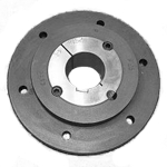
          I purchased the bolt on hub and taperlock bush.

          It is great having lots of talented electro / mechanical guys to bounce ideas off.

          I did mean 90mm hole in the wheel (disc). The diagram of the bolt on hub with the dimensions just didn't look right for some reason because of a step and incomplete dimensions.

          I started redrawing the wheel and hub in Solidworks this evening only to realise that the dimensions from the links I provided definately were not correct.

          In my efforts to find the correct dimensions, I found the manufacturer too.

          They make a lot of interesting parts:

          Challenge Power Transmission - Chains, Sprockets, Belts, Pulleys and more

          Comment


          • Originally posted by purelyprimitives View Post
            Even though this isn't optimal, an interesting thing is that it is completely scalable. Want more torque...just make the arm longer.
            It kind of reminds me of Mikhail's earlier experiments with the bicycle wheel and window winder motors.

            Only yours is using massive weights.

            It's really interesting how our knowledge of electronics, mechanics and magnetics takes us off in different directions.

            It seems rather than to increase Mikhail's element size and motor size he went for more elements, which is what led him to prototype 11.

            Comment


            • Originally posted by purelyprimitives View Post
              Hi Ron,
              I could try a double ended one but how would I drive both ends with one motor? The motor is an electric seat motor for a car and has tons of torque and easily handles the 2.5 lb weight. I bought it new off of Amazon and it was only $15 so I could just buy another one...or two....hmmm.
              Charlie
              Yeah those motors have to move pie eaters backwards and forwards!

              I can't remember ever changing one on any vehicle, but then again they are not in use much.

              $15 sounds very reasonable.

              As Drak said, very interesting way of using two lots of slip rings.

              How did you calculate the counterweight needed?
              Last edited by soundiceuk; 11-28-2012, 11:03 PM.

              Comment


              • Originally posted by soundiceuk View Post
                Yeah those motors have to move pie eaters backwards and forwards!

                I can't remember ever changing one on any vehicle, but then again they are not in use much.

                $15 sounds very reasonable.

                As Drak said, very interesting way of using two lots of slip rings.

                How did you calculate the counterweight needed?
                To calculate the proper counterbalance, I used the rigorous and precisely detailed scientific method of holding the arm level and just adding weight till it was almost balanced..... Actually, I plan to play with the counterbalance later to see what effect it has on the input power. But I've just started to change it over to my next idea for rotating the weights which will require reversing the motor so I'll have to come with some different logic and I'll need to wire it like a 3-way switch. I'll put up another video when complete and I'll be sure to show the input specs this time .

                Regards,
                Charlie

                Comment


                • Look forward to seeing it Charlie


                  I'm slowly relearning Solidworks again and now I have the hub dimensions I have made a little bit of progress.


                  The best thing about Solidworks is you can clearly see whether something will fit or not and easily play with the sizes.

                  I haven't drawn the detail of the taperlock bush yet.


                  Still quite a bit of work to do, but for a 1:3 / 1:2 scale replica I'm sure I will manage.

                  The next part is to work out the interference / press fit for one way bearings in the disc (wheel) and decide whether it should be water jetted or machined from either steel or aluminium.

                  I might add some spokes too, to reduce the drag.

                  Best regards,

                  Paul

                  Comment


                  • Originally posted by purelyprimitives View Post
                    But I've just started to change it over to my next idea for rotating the weights which will require reversing the motor so I'll have to come with some different logic and I'll need to wire it like a 3-way switch.
                    Hi Charlie, look into a H-bridge controlled by a microcontroller such as an Arduino. That combination would allow you to run a dc motor forwards / reverse and at different speeds using PWM (pulse width modulation). It also can allow you to brake the motor selectively and with PWM also. By trying this route, and using all dc motors for weight movements, it might be possible to forego the one way bearings altogether.

                    Good Luck, Ken

                    Comment


                    • Originally posted by kenssurplus View Post
                      Hi Charlie, look into a H-bridge controlled by a microcontroller such as an Arduino. That combination would allow you to run a dc motor forwards / reverse and at different speeds using PWM (pulse width modulation). It also can allow you to brake the motor selectively and with PWM also. By trying this route, and using all dc motors for weight movements, it might be possible to forego the one way bearings altogether.

                      Good Luck, Ken
                      Hi Ken, Thanks for the suggestion...I'll definitely look into that.
                      Watching others struggle with the one-way bearings is one of the reasons I'm looking into alternative methods for rotating and holding the weights. I think I have a scheme that will be pretty simple for reversing the motor and I would really like to keep this as simple as possible so that if it works out it would be easy enough for others to build.

                      As Paul mentioned in a previous comment, Mikhail did do something similar a while back with a bicycle wheel and window motors. I don't know why he didn't continue to develop that idea but probably felt that having many more rotating weights was better and using 32 window motors would be cost prohibitive.

                      Best regards,
                      Charlie

                      Comment


                      • Easy and cheap one-way latch

                        There is an easy way to make a one way latch or ratchet that will hold in any position. I thought it was mentioned earlier in this thread but was not tried as far as I know. All you need is a coil spring that is slightly smaller than your shaft. If we were looking at the coil from one end we need a spring that is wound clockwise from the other end towards the end closest to us. The other end needs to have a section straightened out for an anchor leg. Now slide the shaft into the spring by turning the shaft counter-clockwise. Anchor the straight section of spring to the wheel and then try turning the shaft. It will only turn counter-clockwise just like we want. If we try to turn it the other way the spring will tighten up and not let it turn. Now all you need is a simple bearing or even a bushing to mount the shaft in for test purposes.

                        Respectfully,
                        Carroll
                        Just because someone disagrees with you does NOT make them your enemy. We can disagree without attacking someone.

                        Comment


                        • Originally posted by citfta View Post
                          There is an easy way to make a one way latch or ratchet that will hold in any position. I thought it was mentioned earlier in this thread but was not tried as far as I know. All you need is a coil spring that is slightly smaller than your shaft. If we were looking at the coil from one end we need a spring that is wound clockwise from the other end towards the end closest to us. The other end needs to have a section straightened out for an anchor leg. Now slide the shaft into the spring by turning the shaft counter-clockwise. Anchor the straight section of spring to the wheel and then try turning the shaft. It will only turn counter-clockwise just like we want. If we try to turn it the other way the spring will tighten up and not let it turn. Now all you need is a simple bearing or even a bushing to mount the shaft in for test purposes.

                          Respectfully,
                          Carroll
                          Actually that is a very good idea. You would need a strong spring though. Thank you citfta. Good thinking

                          Comment


                          • Originally posted by kenssurplus View Post
                            Hi Charlie, look into a H-bridge controlled by a microcontroller such as an Arduino. That combination would allow you to run a dc motor forwards / reverse and at different speeds using PWM (pulse width modulation). It also can allow you to brake the motor selectively and with PWM also. By trying this route, and using all dc motors for weight movements, it might be possible to forego the one way bearings altogether.

                            Good Luck, Ken
                            Hi Ken, thanks for your input.

                            Could a similar setup be used to control a super fast actuator with a reading from an inductive pickup or hall crank sensor?

                            Cheers,

                            Paul

                            Comment


                            • Update 30th November 2012

                              I'm still playing with the disc design.

                              I have decided to go with 6mm mild steel as it is cheapest for the sheet.

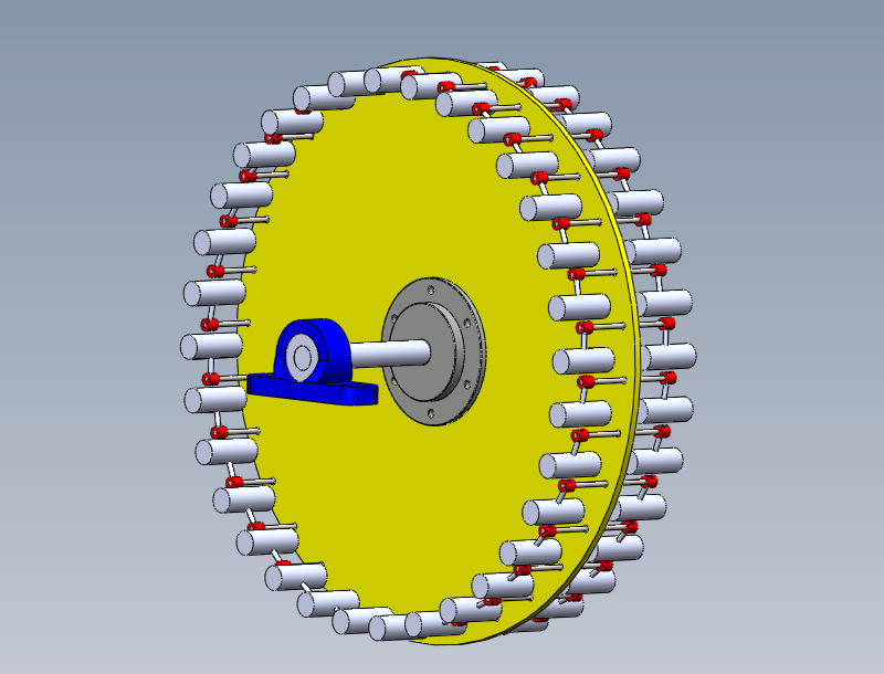
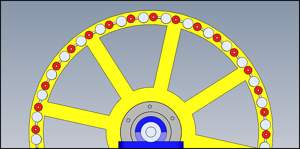
                              This drawing is for a 1:3 scale replica of Mikhail's prototype 11.

                              It shows the clearances on the deflecting elements and not the positions when in motion.


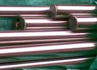
                              I have purchased 4 of these today for 4 deflecting element shafts.

                              4MM TITANIUM ROD BAR SHAFT 100MM MODEL MAKER GRADE 5 ENGINEER | eBay


                              Probably a little overkill but 4mm rod is quite thin (Mikhail's are 12mm). They are also cut to size and I couldn't find any hardened steel rods in this size.

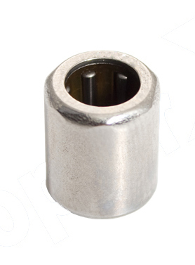
                              I have also purchased 5 x 4mm ID, 8mm OD x 6mm length


                              HF Series One Way Needle Clutch Roller Bearings | eBay

                              One is for a destruction test.

                              I plan to use 6 of the diametric magenets that I have already to prove whether this can be a self runner with no input power other than magnetic repulsion.

                              All the best,

                              Paul
                              Last edited by soundiceuk; 11-30-2012, 03:21 AM.

                              Comment


                              • Originally posted by soundiceuk View Post
                                Hi Ken, thanks for your input.

                                Could a similar setup be used to control a super fast actuator with a reading from an inductive pickup or hall crank sensor?

                                Cheers,

                                Paul
                                Hi Paul,

                                Yes the Arduino board has (depending on the model) a number of analog I/O lines and digital I/O lines. For example here is a quote from the arduino website:
                                "The Arduino Mega 2560 is a microcontroller board based on the ATmega2560 (datasheet). It has 54 digital input/output pins (of which 14 can be used as PWM outputs), 16 analog inputs, 4 UARTs (hardware serial ports), a 16 MHz crystal oscillator, a USB connection, a power jack, an ICSP header, and a reset button. It contains everything needed to support the microcontroller; simply connect it to a computer with a USB cable or power it with a AC-to-DC adapter or battery to get started. The Mega is compatible with most shields designed for the Arduino Duemilanove or Diecimila."

                                Because it has a clock speed of 16 mhz I would be fairly certain that it would be fast enough to read a hall or optointerrupter or any other position sensor and to fire an associated H-bridge. I believe there are some people using a setup like this to run a bedini pulse motor / generator.

                                I found a arduino mega 2560 clone board for about $18 US.

                                Hope this helps,
                                Ken

                                Comment

                                Working...
                                X