Announcement

Collapse
No announcement yet.

Mr Lester J Hendershot's magnetic generator.

Collapse
X
 
  • Filter
  • Time
  • Show
Clear All
new posts

  • Originally posted by GSM View Post
    Thanks for the links Wings, especially at the end of the first one.

    You made me realise that in this situation the magnet is like a pressurising head of water which never becomes reduced because it is permanently maintained, and the sudden end of armature field changes might be just like a self sustaining water hammer/ bouncing ball valve effect which relates to the oscillating length of water column (armature) delay, acting relative to a phase delayed ball valve actuation (R-L-C SS field switching?).

    Cheers .......... Graham.
    consider the use of one shorted coil in the following picture,
    - harm in neutral position - flow straight minimum shortest route
    - sharp impulse on one coil (low power because of neutral position)- crossflow
    - shorted coil current reaction - inverse crossflow
    ecc ..... energy recover with?

    added
    by this ?
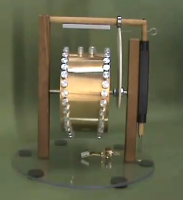
    ETERNAL POWER - YouTube
    Attached Files
    Last edited by wings; 12-04-2012, 03:32 PM.

    Comment


    • Do you see a correlation between these two devices


      Permanent Magnet Motor V-gate Re-gauging from Roobert33 - YouTube
      Hendershot did it
      Half of the Answer is knowing the right Question

      Comment


      • Originally posted by Dave45 View Post
        Do you see a correlation between these two devices
        Hendershot did it
        Did he ? Please explain.

        Hi Dave -
        Have you checked out the 'neutral zone' of an armature or keeper yet - where fractional physical movement induces instantaneous (non-linear) armature or keeper field reversal ?

        This is completely new to me, and is what I am presently investigating as per Wesley Gary's findings replicated by Chris above.

        So far I have observed this positional neutral zone field alternation close to a horseshoe magnet, but as yet I have been unable to induce similar near single neodi magnets.
        Nor am I aware of any neodi horseshoe magnets being manufactured/ available/ sold anywhere.

        Hi Chris.

        I note you mentioned making your own horseshoe magnet out of steel and neodi magnets and I can understand why.
        It appears to be the asymmetry at the horseshoe poles which leads to the 'neutral zone' phenomenon developing.

        I am about to try neodi magnets as pole face intensifiers on the ends of alnico horseshoes which should sink the reverse field nicely away from any working armature.

        Cheers ......... Graham.
        .

        Comment


        • Hendershot built an electronic version of the V gate, notice the positioning of the coils and magnets,
          Half of the Answer is knowing the right Question

          Comment


          • Neat reference -

            http://www.bearsoft.co.uk/new_site/hisch/em-mag.pdf
            .

            Comment


            • Graham,

              The neo's are simply too strong for this purpose. Even ceramics are at the edge of being overpowering, at least in the Gary configuration. You might try TINY neo's UNDER the horseshoe legs, i.e., at 90° to the ends.

              Dave45, your intuition serves you well. However, it's not the POSITION of the COILS, it's the position of the WAVE that moves through them.

              Chris

              Comment


              • Originally posted by Dave45 View Post
                Do you see a correlation between these two devices


                Permanent Magnet Motor V-gate Re-gauging from Roobert33 - YouTube
                Hendershot did it
                hello Dave45,
                clarence here-

                I was looking at the hendershot photo view you show in your post and it finally jumped out to me that there wasnt any capacitors inside the basket weaves! rather that was where the two transformers were placed and you could see their four wires leading in and out.! I also used the VIEW button on the top left of my computer and went to the 400% click and there is a whole lot of useful information that becomes available when you do that.

                I am at presently compareing all of the wire routeing that becomes apparent! also I noticed that all of the capacitors were outside the baskets! I noticed that the magnet and bar showed that the magnet was the type with the odd magnetron shape fron a radar type magnetron setup that he had salvaged! the buzzer coil setup was built on a bolt screw type adjustable araingement.

                there does seem to be a type of thin metal inner backing as an inside containment wall to the baskets. however I have not noticed any kind of wires leading from this metal area. just my observations for now I will get back with the wire routing when I am surely positive about what I see! till then LOL, mike,onward!

                Comment


                • Originally posted by clarence View Post
                  however I have not noticed any kind of wires leading from this metal area. just my observations for now I will get back with the wire routing when I am surely positive about what I see! till then LOL, mike,onward!
                  http://www.energeticforum.com/renewa...tml#post210755

                  Comment


                  • Hey Clarence I noticed that too, its said he built several different versions, I think the transformers would work better in the magnetic field of the basket coils than the caps.
                    I found these caps at mouser 1000 uf capacitor Film Capacitors | Mouser Im not sure if they will work what do you guy's think they are not electrolytic they are film used in dc filtering.
                    Half of the Answer is knowing the right Question

                    Comment


                    • Dave45

                      I believe this b&w photo even if looks old is not the original working device. Am I right GSM ? If so, posting such is a danger of distracting people from the right path of replicating original device into the oblivion of someone else replication attempts...

                      Comment


                      • Once the system was built it would be easy to move components around, Im planning on building the basket coils on separate plexiglass sheets so I can move there positions relative to the magnet.
                        The buzzer coils have my attention these coils are drawing from the electric field of the magnet,
                        According to science a magnetic field resist's change of current flow in an inductor, the magnetic field of the magnet is resisting change in the current flow of the buzzer coils by adding to the current, this magnetic orientation needs to be studied, this shows us how to draw energy from a permanent magnet.
                        Half of the Answer is knowing the right Question

                        Comment


                        • Originally posted by boguslaw View Post
                          Dave45

                          I believe this b&w photo even if looks old is not the original working device. Am I right GSM ? If so, posting such is a danger of distracting people from the right path of replicating original device into the oblivion of someone else replication attempts...
                          Hi Boguslaw.

                          There are only two photographs I believe to be genuine and non-distraction records of a working Mk3 Hendershot generator;-
                          one being the board demonstrated by Lester himself empowering a tube radio receiver;
                          the other being one with clamp tuning whilst an on-board lamp is illuminated.

                          We cannot counter the activities of those who willfully distract, and worse we cannot help those who become distracted, but PLEASE, will everybody here consider this fact -
                          Lester Hendershot constructed his generators using components manufactured in his day - so any circuit using 1,000uF 400Vac capacitors is NOT going to be a Hendershot generator, especially if the coil assemblies are widely separated, and not even tin/ferrous or chrome/ferrous metal cored !!!!!
                          Heck - anyone could run fine wires up a table leg to remotely illuminate a bank of incandescent lamps !
                          CRITICAL THINKING AND DISCERNMENT REMAIN ESSENTIAL AT ALL TIMES.

                          It has always been my understanding that field coupling between the Mk3 basket weave coil assemblies would be necessary, as indeed would have been the case with basket weave coil couplings to other windings in the Mk1-2.
                          Thus it is possible that Lester favoured this method of coil construction, not only because of reduced inter-turn self capacitance, but because when completed and varnished or waxed, these coils would retain their form even after the fine wooden supports had been cut away from their original construction base, hence allowing a completed assembly to be moved about and positioned as necessary.

                          Though stuck for 'hands-on' time here at the moment, I'm hoping to video the 'buzzer' 'neutral zone' field reversal reported by Wesley Gary, and yes Chris I do agree with you that this effect is indeed easier to observe when less powerful magnets are used.

                          Cheers ........... Graham.
                          Last edited by GSM; 12-10-2012, 12:32 PM.

                          Comment


                          • [QUOTE=Dave45;217930]
                            The buzzer coils have my attention these coils are drawing from the electric field of the magnet,
                            QUOTE]

                            Yes a first essential step as outlined by Chris.

                            The buzzer coils are transducing domain alignment change withing the armature, it being the armature which 'draws' upon the magnetic field potential, through alternately induced states of physical field domain alignments, followed by motional electrical kinetic coil transduction.

                            Cheers ......... Graham.
                            Last edited by GSM; 12-10-2012, 12:35 PM.

                            Comment


                            • Though stuck for 'hands-on' time here at the moment, I'm hoping to video the 'buzzer' 'neutral zone' field reversal reported by Wesley Gary
                              Will be interesting to view your findings, thanks for sharing. This weekend I played with a previous project I have been working on for awhile, it will all come together when its time.
                              Im going to wind the buzzer coils this week and play with them a bit, I cant afford the caps at the moment with Christmas and all, I thought of trying to make my own and have been researching it some, it seems doable consistency would be the trick.
                              Half of the Answer is knowing the right Question

                              Comment


                              • I would think the high capacitance is to bring the frequency down to usable levels the frequency of the magnets field is unusable in its present form.

                                GSM I like the idea of cutting the basket coils free from the board, why didnt I think of that good idea bro.

                                It got mighty cold in Texas today, my shop is frigid I need to borrow some of that magnets field to run my heater
                                Half of the Answer is knowing the right Question

                                Comment

                                Working...
                                X