Announcement

Collapse
No announcement yet.

Mr Lester J Hendershot's magnetic generator.

Collapse
X
 
  • Filter
  • Time
  • Show
Clear All
new posts

  • GSM
    replied
    Originally posted by citfta View Post
    Hi guys,

    Chris had asked me a few weeks ago to look at this thread since I am a ham operator. I guess he thought that would give me some kind of inside knowledge. Sorry Chris I haven't really studied any radio circuits in years. I have been very busy getting moved into a new work shop. Tonight I was too tired to do anymore so I started studying the Pdf that was posted a few posts back.

    Chris and Graham I agree with most of your ideas about the Mark 1 version. I do have a couple of thoughts I would like to add. In the sketch on page 37 the wire going to the center of L6 is shown as going to the bottom of the "resonator". I think that may be correct if it was actually going to a contact that was touching the resonator. Then when the resonator was pulled towards L4 the circuit from the resonator to L6 would be broken. Just like a normal buzzer contact.

    Now whether it connects there or at the top where is the energy coming from to energize L6 and neutralize the magnets field? I think there must have been some kind of antenna or energy gathering device for this to work. Maybe it was only a small plate of metal to get things started but I don't see it working without some kind of energy actually going to L6.

    Thanks for inviting me to join the thread. I'll try to at least keep up with what is going on as I work to get the rest of my stuff moved and the new shop set up. Maybe later I can join you guys building a working free energy device!

    Respectfully,
    Carroll
    Hi Carroll.

    I wonder if I need a different download, or if different versions of the same publications have differently numbered pages.

    I printed off this one last year, and setting out several pages beside each other is invaluable for overviewing the bigger picture in a way that single page computer viewing simply cannot provide.
    http://www.rexresearch.com/hendershot2/HendershotMystery.pdf

    My page 37 shows four different tuning oscillator sections, there being an 'antenna' connection to the brass end plate of all Mk2 possible illustrations, with same connection to the resonator.

    My page 19 shows a wire from the 'antenna' tapped to L6 centre.

    My page 33 shows antenna wire 5 going to resonator core, as per Mk2.

    Whilst it is possible there was a 'buzzer' contact on the resonator core, I have not come across that being stated.
    Last edited by GSM; 10-19-2012, 08:39 AM.

    Leave a comment:


  • GSM
    replied
    Originally posted by john_g View Post
    Hi All

    So it could be that the 500khz was used as a switch for the magnetic field?
    Or maybe the earth field was a diversion.

    Anyway, just thought I'd share!

    Regards

    John
    Hi John,

    500kHz might be a good frequency to listen to EM radiated lightning, but what are the field strengths from distant strikes - uV/m !!!!!
    Re that map, I live in the grey coloured region, with dull damp ion earthing weather to match, also 6 months cold, hence I need a source of energy.

    Do not be distracted by *expensive* offerings of HV oscillators capable of capturing but a few extra 'free' milliwatts. If we get the Hendershot generators sussed, that same outlay will provide 100s of watts.

    500kHz was mentioned as the self resonant frequency of Hendershot Mk3 coils too, but that was measured in isolation before interconnects and the 7.8nF tuning capacitor were added; these must have brought high oscillation frequency components down to circa 100kHz.

    In his Mk1, Hendershot wavewound coils also likely self resonated around 500kHz, though here they are additionally connected to the output load, so again I doubt very much they pulse resonated anywhere close to that during operation.

    Hope you stay on board and become 'hands-on' here.

    Cheers ......... Graham.
    Last edited by GSM; 10-19-2012, 07:06 AM.

    Leave a comment:


  • ChrisW
    replied
    Welcome, Carroll!

    Greetings, Carroll!

    Glad you could join us! Sounds like you're still busy getting the new workshop set up. I'm sure you'll enjoy it when it's finally complete and all the dust is but a memory.

    As stated previously, I'm quite sure that when things are properly aligned physically, the device will be self-starting due to the magnetic interactions in such close proximity. As for L6, I'm inclined (right now) to say that it gets its current from the basket weave coils (since it's physically in series with them); my earlier description was one step behind in the sequence of things. In other words, the current passing through L6 is not the CAUSE of action, it's the EFFECT of action.

    I was thinking a couple nights ago that the honeycomb coils (L8A and L8B) almost certainly had to have a large number of turns, but in reading the patent application earlier this evening, it states (in the Mark II section) that they only have ONE turn each. Hmmm! That's almost hard to believe. Granted, that's still a lot of wire due to all the vertical zig-zagging, but it hardly seems enough. Heh-heh. I can almost hear the voice of Tim Taylor in my head saying "More power! Arh-arh-arrrrh!"

    I'll be working on the feedback section over the weekend. Pictures coming soon!

    Speaking of which, can someone kindly type up a quick tutorial on uploading pics (embedding them, that is), just to make sure I don't screw it up.

    More to come...
    Chris

    Leave a comment:


  • citfta
    replied
    A couple of thoughts

    Hi guys,

    Chris had asked me a few weeks ago to look at this thread since I am a ham operator. I guess he thought that would give me some kind of inside knowledge. Sorry Chris I haven't really studied any radio circuits in years. I have been very busy getting moved into a new work shop. Tonight I was too tired to do anymore so I started studying the Pdf that was posted a few posts back.

    Chris and Graham I agree with most of your ideas about the Mark 1 version. I do have a couple of thoughts I would like to add. In the sketch on page 37 the wire going to the center of L6 is shown as going to the bottom of the "resonator". I think that may be correct if it was actually going to a contact that was touching the resonator. Then when the resonator was pulled towards L4 the circuit from the resonator to L6 would be broken. Just like a normal buzzer contact.

    Now whether it connects there or at the top where is the energy coming from to energize L6 and neutralize the magnets field? I think there must have been some kind of antenna or energy gathering device for this to work. Maybe it was only a small plate of metal to get things started but I don't see it working without some kind of energy actually going to L6.

    Thanks for inviting me to join the thread. I'll try to at least keep up with what is going on as I work to get the rest of my stuff moved and the new shop set up. Maybe later I can join you guys building a working free energy device!

    Respectfully,
    Carroll

    Leave a comment:


  • ChrisW
    replied
    Focus

    John, and all contributors to this thread:

    While your enthusiasm and creativity is appreciated and lauded, I'd very much like to keep this thread on topic and focused on Hendershot and his work. We have something on the table now that holds great promise and potential.. Let's do our best to stay focused and avoid wandering off into the forest.

    Thanks for your understanding....
    Chris

    Leave a comment:


  • ChrisW
    replied
    Hey John,

    There's no shortage of RF and atmospheric devices in the history of FE devices. If the psychopaths hadn't taken over at the turn of the last century, we'd have structures capturing the energy that's abundant all around us; instead, we have nuclear plants poisoning the planet and its inhabitants.

    Hendershot's work is unique in that it doesn't require woo-woo to explain it (which is not to say that woo-woo is a bad thing, other than its requirement of a budget that would finance small nations, along with access to unique and exotic materials, the best minds on the planet, etc.). Hendershot's design is simple, affordable and low-tech. Even if the Mark I only provides enough power to run a small lamp or a few dozen LEDs, it's one less bulb on the grid and one step closer to self-reliance for all of us.

    The above leaves me wondering two things: 1) how small can it be made, and 2) how LARGE can it be made? One's imagination can go wild with questions like these.

    More to come...
    Chris

    Leave a comment:


  • john_g
    replied
    Lighting Map

    Thought this was of interest - a map of world lighting strikes. Note that Congo/Rwanda has the highest world rate - maybe linked to their appalling circumstances?

    Leave a comment:


  • john_g
    replied
    Hi All

    Most of you are far more experienced than me but I thought I’d share my thoughts with you all. I must admit that it has been some time since I had a look at the Hendershot device, and looking at other devices I think I can see some common threads occurring, though maybe at odds with the excellent research here.

    I’m wondering if Pat 2143437 may hold some clues? You will see the D shaped device with coils/magnets. This transforms an incoming ac wave to an output pulse – maybe a variation of the buzzer used?

    Re the 500khz, this is the frequency of lightning pulses. In this PDF, ELECTROMAGNETIC SIGNATURES OF LIGHTNING NEAR THE HF FREQUENCY BAND explains:

    https://www.doria.fi/xmlui/bitstream...pdf?sequence=1

    So it could be that the 500khz was used as a switch for the magnetic field?
    Or maybe the earth field was a diversion.

    Anyway, just thought I'd share!

    Regards

    John

    Leave a comment:


  • ChrisW
    replied
    Simplicity

    Graham,

    Yes! While everyone back in the day was piling on the woo-woo about psychic powers, earth's magnetic field, mystique and mumbo-jumbo, they overlooked the obvious. It's shocking how "science" just pulls down its pants and excretes an enormous, stinking pile of dung on someone who discovers the simple and obvious. 'Oh, that's not possible," they say. Well, I salute those brave souls who had the courage to say "Well, that magnet on the refrigerator is holding up a piece of paper. Isn't that WORK being done?" Response from "science:" A big, flatulent "phhhhhhhtttttt."

    The most amazing and remarkable thing about the Mark I is that it's ALL being done with coils. No capacitors, relays, semiconductors, none of it!

    If everything's positioned properly, it's quite likely that the small amount of ambient EM noise in the environment could get the oscillations started; otherwise simply injecting a short pulse from a small battery would do the trick. Hell, one little solar cell could accomplish that.

    Your idea of using a small spring to sharpen up the response is excellent. Once you've proven that the idea works, how about replacing it with a hall effect sensor and a transistor? Speed! (Finding an appropriate spot to ground it is the only issue I foresee with that idea).

    You're probably right about another thing. "They" probably obfuscated the whole thing with their dung piles so you WOULDN'T see and recognize the obvious. Sad, pathetic little control-freak psychopaths. It almost makes you feel sorry for them. Almost.

    Well, the beans have been spilled, the cat is out of the bag -- insert your own metaphors here. It's clear what we must now do. Let the work begin, let imagination run wild!


    Chris

    Leave a comment:


  • GSM
    replied
    Originally posted by ChrisW View Post

    The "antenna" is nothing more than a bloody counterweight! It provides enough "gravitational energy" (that phase used very much with tongue in cheek) to pull the vertical "resonator" away from the end of L4's core. The "antenna" and resonator strip are one piece of metal with a 90° bend in it.

    Chris
    'Antenna' - yes a mechanical return force makes sense.
    So that 'antenna' could even be an adjustable torsion bar spring+mounting arrangement for the vibrator leaf - enabling better defined and higher frequency vibration characteristics ?
    Now that really would look like a little wire antenna !

    Could it really be that the Mk1 is so basic, and that we have been so misguided by those texts ?

    Cheers ............. Graham.
    .

    Leave a comment:


  • ChrisW
    replied
    I can see clearly now, the rain is gone

    Greetings, Graham,

    You've brought up some good points, and indeed, you're very much on the right track with the Mark I.

    Graham, the operation of the Mark I is so simple I'm surprised I didn't come up with the design myself. ANYONE on this forum with a good understanding of coils and magnets can "get" the concept by studying the Mark I, with their "monkey mind" turned OFF. It's NOT complex. Yes, I still have a few questions about some of the particulars, and these questions will be answered by empirical data and observation.

    In confirmation of your assessment that Hilton contains some rather wild assumptions, perhaps even BS, yes, I concur. That whole gigahertz-broadband thing is an exercise in bovine scatology, to quote a famous American general.

    The "antenna" is nothing more than a bloody counterweight! It provides enough "gravitational energy" (that phase used very much with tongue in cheek) to pull the vertical "resonator" away from the end of L4's core. The "antenna" and resonator strip are one piece of metal with a 90° bend in it.

    There must be enough turns on L6 to cancel out M7's magnetic field at both poles. Thus, L6 is wound like one of Tesla's coils, i.e., from the middle outward, in opposite directions. When L6 is energized (M7's field canceled), L13 and L14 are active, establishing a crosswise field east and west, if you will. This is analogous to moving the compass needle with one's finger into the east/west direction. This causes the resonator to be attracted to L4's core, effectively grounding out L6, which restores M7's field, thus the proverbial compass needle swings back into north/south alignment. In essence, it's the power of making and breaking of M7's magnetic field which makes the whole thing work. The honeycomb coils "see" the changing magnetic field and act like any coil does in a changing magnetic field.

    I probably didn't do justice to the device in my explanation, but that's the gist of it. It's the cancellation and restoration of M7's field, at the same time, flipping the polarity of the L13 and L14 coils, that cause a moving, if not rotating, magnetic field through the honeycomb coils.

    Ponder on this, you'll see it. It's not magic, it's simply having enough turns in the right places to convert a current into a magnetic field of the proper polarity.

    Chris

    Leave a comment:


  • GSM
    replied
    Originally posted by ChrisW View Post
    Greetings, Graham,

    Last night I was reading the patent draft; it leaves much to be desired. One thing I did notice, something that Hilton did not catch, apparently, is the description of L6, wherein it states (paraphrasing) that a wire is attached to the middle of the INNER windings. Doesn't this imply that an OUTER layer might exist? Why use the word INNER if there is no OUTER?

    Chris
    Hi Chris,

    In concurrence with your stated thoughts I too am now studying the Mk1.
    My reasons -
    - Known to be light of weight for power generated, hence efficient of materials.
    - Once the principles are figured out, it would not take hours or weeks to tune up like the Mk3 does.

    Something else I have noted from the notes, and relating to the Mk1 -
    Lester's wife is reported to say it worked only in the N-S direction, whilst he himself stated that the rotary motion was produced in an E-W direction.

    Two points arising.
    Was his wife looking at the toy plane, and Lester looking at coil alignments ?
    Even then, could Lester have told his wife to align the wings N-S, and not the fuselage ?

    Yesterday I wrote here about 'professional liars', these being people who will controllingly look you in the eye and bare facedly speak lies as if they are the truth, for 'professionals' are free to lie when they know that you have no way of challenging their statements either directly, or subsequently via a Court of Law. The experience of such an occurrence IS life changing, and this is exactly what happened to Hendershot in his pursuit of that Patent application, which he was likely encouraged to file for 'commercial' reasons.
    Poor Lester fell into a veritable viper's pit, and from that moment on, not only was he controlled, but the information about his Mk1 and Mk2 generator designs were controlled too.

    Thus I have come to believe that the notes formally published about the Mk1 and Mk2 designs exist only because they contain deliberate disinformation, for anything else would have been made to disappear !

    Additionally, separated drawings of portions of the circuit in isolation over-ride our mind's-eye abilities to focus upon the whole, especially when the 'complete circuit' representation is not correct either !
    There is even written "possible broad-band gigahertz receiver" where the central L6 assembly resides, but it is impossible for multiturn inductors to transduce gigahertz !

    Getting back to your observation Chris, and that L6 tuning coil where you spotted the description of its centre tap wire being attached to the middle of the 'inner' winding:
    So maybe there are two separate windings of outwardly overwound electrically centre-tap balanced layers upon a common former, or, just an internal centre tap.
    Either way, if the other L6 connections came from opposite ends and there was an internal centre tap, then L6 must have had an 'odd' number of layers greater than one.

    I still want to check out the winding/ field alignments of L6 with respect to L13 and L14, and other resonator aspects.
    Could Lester's mechanically tuned magnetic resonator assemblies be replaced by a more conventional tuned L-C arrangement, possibly an updated one energised by a transistor oscillator, as in direction finding equipment ?

    L6 is also shown to be wound around M7, thus indicating a permanent magnetic core,
    and yet a permanent magnet core cannot but render assymmetrical any coil induced field, unless,
    that magnetic core has a deliberately weak field such that all it might do is cancel the Earth's natural field and leave L6 working entirely naturally within the honeycombs ?
    Or could it be that there are a pair of polarly opposing magnets glued together which appear like a normal magnet at their outer ends, but where the L6 overwind could then induce a resultant rotating field within the honeycombs ?
    If L6 is to do no more than electromagnetically energise a physically resonant metallic element, is it merely influencing the field of L6, or is there some other undocumented circuit coupling ?

    Is it possible that an L6 induced alternating or rotating field could cyclically augment the field of the simultaneously energised honeycomb winding,
    and thus spatially energise L13 and L14 equally but oppositely,
    which might then serially energise L4,
    and thence the L19 + L22 + L25 windings,
    all of these constituting a 360 degree phase shifted feedback loop between output and L6, this being a requirement for self sustainably of oscillation ?

    As I mentioned before, I believe that the transformer laminations stated to surround L19 and L25 are deliberate disinformation to ensure that replicators could never succeed, though there might well have been a silver painted grained wooden frame to support those fine wire windings, this giving the impression of transformer laminations. Certainly no gigahertz possilities here, and thus not with the directly connected L6 and honeycombs either !

    As per 'The Hendershot Mystery' notes -

    http://www.rexresearch.com/hendershot2/HendershotMystery.pdf

    Page 21, figure 3.3 and page 23 figure 3.4 (without external laminations as indicated) are similar. These might operate mutually out of phase in different planes of polarisation, and thus amplify the potential necessary to re-empower the page 19 figure 3.2 circuit ?

    Lester steadfastly explained that the principle empowering his generator relied upon alignment with the Earth's N-S magnetic field, but with E-W component inducement of a rotating field. Yet both of his Mk1 and Mk2 designs have coils vertically aligned as well, possibly facilitating triple axis augmentations without mutual interferences.

    Hope all you folks can understand my ramblings, and maybe even expand upon my thoughts.

    Cheers ........... Graham.
    .
    Last edited by GSM; 10-18-2012, 10:53 AM.

    Leave a comment:


  • GSM
    replied
    Hi John,

    Nice one !

    A thin but powerful neodi magnet on the centre limb of a standard 'E' transformer core would make a nice buzzer with A-B windings and sprung centre pivoted armature !

    Cheers ......... Graham.

    Leave a comment:


  • GSM
    replied
    Hi Boguslaw,

    Magnetic current is one of those flawed descriptions which has not been brought into the fold of atom fundamentals.

    Electrons orbiting an atomic nucleus constitute tiny magnets.
    In soft iron these are random until aligned by a field.
    In magnetised substances the molecules preserve electron spin alignment through the molecular structure.

    Put a soft iron keeper on a magnet and the permanent field will align electron orbits in the keeper.

    Like charge motions attract, opposite repel, hence like electron spins attract.
    Like spins within the molecular structures (domains) pull a keeper to a magnet, and also give rise to the phenomenon of magnetostriction.

    There is no magnetic current flowing through a magnet keeper, but it will remain attracted for as long as the magnet remains polarised, which is assisted by closing the field through the keeper.

    All magnetic effects and properties can be reduced to atomic characteristics, and thus it becomes easy to understand why heat causes a magnetic to lose strength.

    Must check out page 45.

    Cheers .......... Graham.

    Leave a comment:


  • john_g
    replied
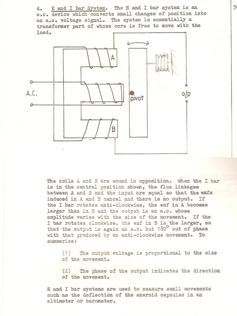
    E & I bar System

    Hi

    Not sure if this is helpful or not, but I thought about the E & I bar system the other night - dug it out from my old course note - sort of thinking out loud as they say!


    Regards

    John

    Leave a comment:

Working...
X