 Tweet
Tweet
thx1138: I think I might have misinterpreted your question. If you mean the kraft paper that is the initial layer on the stainless steel cylinder, I always just used kraft paper available from hobby or craft stores like Michael's or Hobby Lobby. One turn, secured with a tiny piece of tape. Last time, I think I actually secured it with the hot paraffin wax used to seal them up.
-
-
What I've read said the layer next to the inner metal former was "heavy white paper". I was asking about the actual capacitor dielectric paper that goes between the foils. From what I understand it is a very pure cellulose that is specially dried. Everything I've seen at the hobby stores is recycled paper so I'm guessing it could have just about anything in it.Originally posted by ProfessorTinkerer View Post
I have a friend who built asphalt highways his whole life. I mentioned to him that I had seen an article about using recycled tires in the asphalt and he replied that it sounded good but it was kind of like making an angle food cake with 10 lbs of onions because you already had the onions on hand - it just didn't work. I look at this in same way - the wrong materials are going to end up with a bad result.
I've found quite a bit about the capacitor paper on the internet but they are all industrial sources. I read that Hendershot had problems getting the electrolyte out of the paper so I've been trying to find new capacitor paper to avoid that problem. But I guess I'll have to open up some more capacitors.Comment
-
Extrapolation
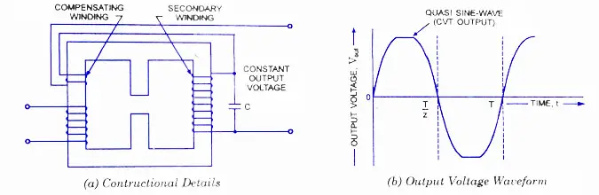
I was recently having a discussion with the chief engineer where I am employed about CVTs or Constant Voltage Transformers. He sketched out his rendition on the blackboard and like the pic here, it had three windings, except in his drawing, the center gap was closed with the 'resonance' winding wound on it, connected to the AC capacitor. Then, a Ta Da moment happened. Look familiar? Sure, the H-shot cap/coil assembly isn't necessarily 'ferro-resonant' (no real iron mass), but the topology is very similar. Could we make a guess that the H-shot cap/coils are really CVTs, only at a much higher frequency? The cylindrical cap and the outer winding serve as the resonance feedback for the other three windings? Couldn't help but notice the similarity, as I had never noticed this aspect before. Food for thought.
Comment
-
Professor Tinkerer: I've seen some Hendershot schematics that show the capcoil cap connections similar to what you show but I haven't spent any time with them yet. I may get back to that later.
I've finished my build except for the capcoil caps. I thought I would do some testing while I think about those capacitors. The testing has shown me a couple of things of interest.
I'm using a 120V, 60Hz variac to feed variable voltage power into the circuit like the J. G. Gallimore schematic shows as a startup mechanism on the right side of the ringer coils.
Following the idea that someone posted that the capcoils were just eye candy to distract from the true functioning of the device I used no capacitor, 1.3uF and 7.8nF off the shelf capacitors in my tests while taking readings at 30, 60, 90, and 120 volts and different spacings of 3/4" to 0" from the ringer coils to the magnetron armature and with the armature removed and the coils even with the magnet poles and inside the magnet poles.
The capacitors definitely make a difference but I didn't see any marked improvement with them. I'm thinking a may need much higher frequency AC for my testing. Considering Lester's relationship with the air force and the fact that the magnet is a magnetron magnet, I'm thinking 400Hz might be better - that being the frequency for most aviation power. But I'm not sure how to build a variable voltage, variable frequency, pure sine wave AC power supply. It's one of the things I'm looking into because the commercial units I've seen are in the $1000s. I have a function generator but it is far too weak to use for any testing.
Noticing that the ringer coils had a wider side-to-side spacing on the one photo of the working Hendershot device and all other photos I've seen (Aho, Skilling, and Mark Hendershot), I also varied that spacing and found that the ringer coils need the wider spacing. They were shown where the their cores were about half way between the center of the magnet and the outside poles. That setup gave immediate results of about 20% increase in throughput. Moving them out to a position centered on the end poles of the magnet gave slightly more improvement - 1 to 2% more.
I tried different ringer coil mounting materials as well. The coil cores have tapped holes in one end and I mount them to the adjustment sled with stainless steel non-magnetic screws through the mounting material into those threaded holes. I suspected that using the permalloy mount that came with the coils would be the best. But that was wrong. Changing from permalloy to aluminum mounting material gave another 20% improvement. I think that's because the permalloy mount was sucking magnetic flux out of the coil cores so it wasn't inside the portion wound with wire. Changing the mounting material to a non-magnetic material left more magnetic flux in the permalloy cores so gave more output. I also tried perf-board and that gave another 1 to 2% improvement. I think that's because the flux into the aluminum was setting up eddy currents.
I don't have a very good method of making the ringer coil to magnetron armature adjustment so those 1 - 2 % improvements may just be adjustment differences in the armature gap and could be discounted.
I've only tried one schematic so far and don't have anything useable yet. But I will keep plugging along.
Thinking about the capcoil caps and having destroyed too many caps looking for paper, I've decided to take another route. In one of the web sites I found on dielectric constants of various materials they say that Teflon has the same dielectric constant as dry paper - 2.0. Interestingly, that's the same as paraffin also. So I'm thinking that as long as the Teflon film is the same size and thickness as the paper it should work okay. I could not find the original Pyramid combined cap but I did find individual Pyramid caps on ebay and took them apart. The paper is 0.003" thick measured with a vernier micrometer after letting them dry for a month. So I guess I'll try the same thickness Teflon which is plentiful. Opinions anyone?Comment
-
Hendershot Capacitor Build
Hendershot Capacitor Build:
Here are some pics of my build process.
This was the choice of caps I had.
The one with the plastic cover was out of a Blaupumkt colour TV and knew it was damaged as the aluminium container had split but used this as an example of what was inside.

Chose this one as it appeared to suit the bill nicely as it was 4" in length - note the ruler at right hand side.
Removed the top with a small hacksaw and immediately saw that it was centralised in the big can by tar and so had to heat to remove but was much easier then expected.
The tar simply came away once cut off with the first paper wind.
Note the different sizes and the voltage ratings and my choice was the higher voltage but the difference was the huge gap inside.

This is the aluminium foil after cleaning which was also simply done under a running tap using a kitchen scourer but gently.
The cap as Hendershot made had two ends 1" apart at the centre and this is showing how I joined contacts to the cap foil by using pie dish 0.1mm aluminium and used it bent over with the cap foil inside the bend and simply poked a sharp scriber through many times to make contact and this appears to have worked well and is similar to what the manufacturer actually does.
Capacitor value was close to the 7,800pF that Hendershot achieved but note here the length just happened to be just over 182" and all I had to do was cut in half to get the 91" required.

Final shot of the finished product and you can see the two cap leadouts at rhs unit.
The two transformers used here are also from the Blaupunkt and are horizontal driver types (had two) which would be directly equivalent to what Lester was using.
My 'resonator' here is a 4 volt Multivibrator and was the setup that accidentally gave an 11kv spark due to a loose and sparking joint.
However was not able to make the unit resonate.
300 to 500 Watt output and 43khz gets a mention.

Hope this helps in some way and was fun to build and mess with but had to go on to better possibilities which I am currently working on.
The 'resonator' is my only problem here and have not come up with one that can actually induce a voltage into the twin coils.
A great learning experience.
Good luck with your builds.
SmokeyComment
Comment