Announcement

Collapse
No announcement yet.

Mr Lester J Hendershot's magnetic generator.

Collapse
X
 
  • Filter
  • Time
  • Show
Clear All
new posts

  • Focus

    John, and all contributors to this thread:

    While your enthusiasm and creativity is appreciated and lauded, I'd very much like to keep this thread on topic and focused on Hendershot and his work. We have something on the table now that holds great promise and potential.. Let's do our best to stay focused and avoid wandering off into the forest.

    Thanks for your understanding....
    Chris

    Comment


    • A couple of thoughts

      Hi guys,

      Chris had asked me a few weeks ago to look at this thread since I am a ham operator. I guess he thought that would give me some kind of inside knowledge. Sorry Chris I haven't really studied any radio circuits in years. I have been very busy getting moved into a new work shop. Tonight I was too tired to do anymore so I started studying the Pdf that was posted a few posts back.

      Chris and Graham I agree with most of your ideas about the Mark 1 version. I do have a couple of thoughts I would like to add. In the sketch on page 37 the wire going to the center of L6 is shown as going to the bottom of the "resonator". I think that may be correct if it was actually going to a contact that was touching the resonator. Then when the resonator was pulled towards L4 the circuit from the resonator to L6 would be broken. Just like a normal buzzer contact.

      Now whether it connects there or at the top where is the energy coming from to energize L6 and neutralize the magnets field? I think there must have been some kind of antenna or energy gathering device for this to work. Maybe it was only a small plate of metal to get things started but I don't see it working without some kind of energy actually going to L6.

      Thanks for inviting me to join the thread. I'll try to at least keep up with what is going on as I work to get the rest of my stuff moved and the new shop set up. Maybe later I can join you guys building a working free energy device!

      Respectfully,
      Carroll
      Just because someone disagrees with you does NOT make them your enemy. We can disagree without attacking someone.

      Comment


      • Welcome, Carroll!

        Greetings, Carroll!

        Glad you could join us! Sounds like you're still busy getting the new workshop set up. I'm sure you'll enjoy it when it's finally complete and all the dust is but a memory.

        As stated previously, I'm quite sure that when things are properly aligned physically, the device will be self-starting due to the magnetic interactions in such close proximity. As for L6, I'm inclined (right now) to say that it gets its current from the basket weave coils (since it's physically in series with them); my earlier description was one step behind in the sequence of things. In other words, the current passing through L6 is not the CAUSE of action, it's the EFFECT of action.

        I was thinking a couple nights ago that the honeycomb coils (L8A and L8B) almost certainly had to have a large number of turns, but in reading the patent application earlier this evening, it states (in the Mark II section) that they only have ONE turn each. Hmmm! That's almost hard to believe. Granted, that's still a lot of wire due to all the vertical zig-zagging, but it hardly seems enough. Heh-heh. I can almost hear the voice of Tim Taylor in my head saying "More power! Arh-arh-arrrrh!"

        I'll be working on the feedback section over the weekend. Pictures coming soon!

        Speaking of which, can someone kindly type up a quick tutorial on uploading pics (embedding them, that is), just to make sure I don't screw it up.

        More to come...
        Chris

        Comment


        • Originally posted by john_g View Post
          Hi All

          So it could be that the 500khz was used as a switch for the magnetic field?
          Or maybe the earth field was a diversion.

          Anyway, just thought I'd share!

          Regards

          John
          Hi John,

          500kHz might be a good frequency to listen to EM radiated lightning, but what are the field strengths from distant strikes - uV/m !!!!!
          Re that map, I live in the grey coloured region, with dull damp ion earthing weather to match, also 6 months cold, hence I need a source of energy.

          Do not be distracted by *expensive* offerings of HV oscillators capable of capturing but a few extra 'free' milliwatts. If we get the Hendershot generators sussed, that same outlay will provide 100s of watts.

          500kHz was mentioned as the self resonant frequency of Hendershot Mk3 coils too, but that was measured in isolation before interconnects and the 7.8nF tuning capacitor were added; these must have brought high oscillation frequency components down to circa 100kHz.

          In his Mk1, Hendershot wavewound coils also likely self resonated around 500kHz, though here they are additionally connected to the output load, so again I doubt very much they pulse resonated anywhere close to that during operation.

          Hope you stay on board and become 'hands-on' here.

          Cheers ......... Graham.
          Last edited by GSM; 10-19-2012, 07:06 AM.

          Comment


          • Originally posted by citfta View Post
            Hi guys,

            Chris had asked me a few weeks ago to look at this thread since I am a ham operator. I guess he thought that would give me some kind of inside knowledge. Sorry Chris I haven't really studied any radio circuits in years. I have been very busy getting moved into a new work shop. Tonight I was too tired to do anymore so I started studying the Pdf that was posted a few posts back.

            Chris and Graham I agree with most of your ideas about the Mark 1 version. I do have a couple of thoughts I would like to add. In the sketch on page 37 the wire going to the center of L6 is shown as going to the bottom of the "resonator". I think that may be correct if it was actually going to a contact that was touching the resonator. Then when the resonator was pulled towards L4 the circuit from the resonator to L6 would be broken. Just like a normal buzzer contact.

            Now whether it connects there or at the top where is the energy coming from to energize L6 and neutralize the magnets field? I think there must have been some kind of antenna or energy gathering device for this to work. Maybe it was only a small plate of metal to get things started but I don't see it working without some kind of energy actually going to L6.

            Thanks for inviting me to join the thread. I'll try to at least keep up with what is going on as I work to get the rest of my stuff moved and the new shop set up. Maybe later I can join you guys building a working free energy device!

            Respectfully,
            Carroll
            Hi Carroll.

            I wonder if I need a different download, or if different versions of the same publications have differently numbered pages.

            I printed off this one last year, and setting out several pages beside each other is invaluable for overviewing the bigger picture in a way that single page computer viewing simply cannot provide.
            http://www.rexresearch.com/hendershot2/HendershotMystery.pdf

            My page 37 shows four different tuning oscillator sections, there being an 'antenna' connection to the brass end plate of all Mk2 possible illustrations, with same connection to the resonator.

            My page 19 shows a wire from the 'antenna' tapped to L6 centre.

            My page 33 shows antenna wire 5 going to resonator core, as per Mk2.

            Whilst it is possible there was a 'buzzer' contact on the resonator core, I have not come across that being stated.
            Last edited by GSM; 10-19-2012, 08:39 AM.

            Comment


            • Hi Graham,

              It was late when I was typing that post. I should have said page 37 of the Pdf which is actually page 33 of the original document. It is labeled figure 3.8. It looks like there is a little dot where the wire number 5 touches number 2 the "resonator". The dot made me think it might be a contact rather than an actual connection. Earlier in the document the writer mentions this and says he thinks it is a mistake and so he redrew it to the top. I am not so sure about that. If the resonator actually moves and I think it does then it could be like a buzzer contact but I have only just started trying to figure all of this out so I may be way off base in my ideas. Sorry for the confusion on the page numbers.

              Later,
              Carroll
              Just because someone disagrees with you does NOT make them your enemy. We can disagree without attacking someone.

              Comment


              • Hi All,

                Hendershot did understand - (like Tesla did, others and some subscribers here too) - until maybe he thought -
                "I give up trying to start a business. With my physical strugglings and all this wheelchair push-pulling - like my Mk3 generator is perfected and I'm going to share it with all my fellow humans."
                Thus, and VERY sadly .......... his-story ......... was made !

                The worst part about all of this are those dark forces who beleive they are 'it', whilst actually they are mere parasites. It is they who paranoiedly suppress the whole of humanity by ensuring that our children do NOT become properly educated, and watch us to ensure we do not remain free to develop beyond the limitations agreed between their cabalistic dictatorships.
                ___________________

                Yes Hendershot was THE No.1 exponent of NMR generators.

                And that was 50+ years ago !!!!!

                He knew he could offer the future which all mankind still so desparately needs .... and yet .... his knowledge 'died' before he could share it after he filed for that last circuit Patent.

                The same will happen today to anyone who attempts to start explaining Hendershot or similar technology, though Hendershot's was not only the first, but the best too.

                Through his deep natural intuition and endless cups of coffee Hendershot demonstrated a degree of success not achieved by Tesla, Hubbard, Moray or any other lone inventor since then.

                Henderhot's success through all versions of his generators came via the analogue characteristics of his resonant magnetic 'buzzer'. Characteristics which cannot become obvious to those who are not 'hands-on' innovators, and characteristics which simply cannot be replicated via the supposedly equivalent delay-lines of flip-flop oscillating digital switches and power controlling circuitry; nor currently be demonstrated operating with his novel coilpacitors by even the most powerful of computer simulators either !!!!!

                In spite of confusing published notes, I can see from the re-wiring within his already published final Patent application, that Hendershot had indeed worked out exactly what both he and his circuit were doing.

                Every clue to replicate has already been published in 'The Hendershot Mystery' booklet, though definitely not the real modus operandi. Also, had I known at outset what I know now, I would not have written all that I have in this thread, for Hendershot's little generator boards are so far beyond what I first imagined; and TPTB know this too !!!!!

                Sadly I simply cannot allow myself to risk being drawn to suggest any more answers, for I have no wish to be tagged as one who might contribute to the downfall of present day societies via promoting the construction of free energy generators, and this is why I will not be posting any more upon this, nor upon other lesser potential equipments either.

                After so much taxing effort in gaining this 'sorted' knowledge I will be having much more time to share and enjoy what is left of my life endeavours with my family, friends etc.,
                and hopefully my Internet Domain Name Server connection will not, as it has been recently, mysteriously repeatedly dropped out without any traceable faults being identifyable by my ISP. As if - LOL !

                So, and as we all keep paying our taxes, I wish every one of you success in your own individual investigations .... and .... a fond farewell.

                Adios amigos !

                ____________________
                He who believes - needs to talk: He who knows - knows not to. GSM.
                .
                Last edited by GSM; 10-20-2012, 11:42 AM.

                Comment


                • Bravo!

                  Dearest Graham, and all,

                  To you, Graham, I exclaim "Bravo!" Your sentiments were well expressed, clearly and succinctly. My deepest and sincerest thanks for starting this thread, as it was the impetus needed to think through the entire process, to return to the Mark I, to put myself in Lester's shoes and walk as he walked. Like so many others, I too, at first, started right in with the Mark III, with no understanding of the Mark I and its foundational design. For those who will blaze this path, YOU CANNOT REACH THE MARK III WITHOUT FIRST UNDERSTANDING THE MARK I.

                  To the parasites who would attempt to enslave us through their fakery and psychopathic wet dreams of world domination, I would say this: YOU HAVE ALREADY FAILED. No amount of brainwashing, indoctrination, chemical adulteration of the air, food and water supplies, will EVER suppress the human spirit. We are NOT our bodies of flesh. YOU know it and WE know it. You may destroy our vehicles, but you will NEVER destroy US. In the end, yours will be an empire of dirt. Long may you reign over it.

                  To all, the cat is now out of the bag. Take what I have learned and shared with you and BUILD it. Persevere. You WILL succeed. When you do, don't thank me, thank Lester Hendershot. Put the name Hendershot on your device so that his name will be remembered. Share then your knowledge with those who are deserving of it, do not cast your pearls before the swine. Last, a quote from the Desiderata: Walk placidly amid the noise and the haste, and remember what peace there may be in silence.

                  I too, shall now bow out of this thread. To all, be strong, be brave, be the light that burns through the darkness in the days ahead.

                  In love and light,
                  Chris

                  Comment


                  • Graham and Chris

                    Sad to see you both go, but many thanks for your wisdom.

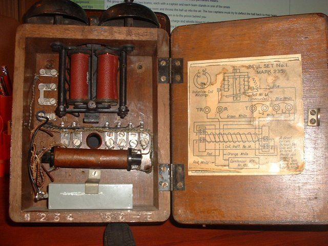
                    For general interest here is a picture of an early telephone set around the time of Hendrshot.


                    Regards

                    John

                    Comment


                    • Sorry, I have to ask : where can I find " published final Patent application" ?

                      Comment


                      • Pdf document

                        Hi Boguslaw,

                        The application I think they are talking about is near the end of the Pdf that is linked to in post 111. The Pdf is about the mystery of the Hendershot device.

                        Carroll
                        Just because someone disagrees with you does NOT make them your enemy. We can disagree without attacking someone.

                        Comment


                        • Originally posted by wings View Post

                          Coupling between Current and Dynamic Magnetization from Domain Walls to Spin Waves ?:

                          http://igitur-archive.library.uu.nl/...1/lucassen.pdf
                          I have been going through and adding all of the links from this thread to my Hendershot folder. The drawings in the first section of that link are good Wings, especially on page 10 (p16 of 86 in .pdf)

                          It seems Hendershot stopped using coffee tins as an internal core for his Mk3 because they stopped working due to 'corrosion'. However the download PDF notes clarified this was not just corrosion, but pin holes right through the tin.

                          I do hope everyone is thinking hard about Hendershots designs.

                          Cheers ........... Graham.
                          Last edited by GSM; 10-24-2012, 04:41 PM.

                          Comment


                          • Telephone Bell Ringer

                            Hi All

                            I've uploaded a video showing a telephone bell ringer connected to a oscilloscope - which may give some clues as to why this may be useful. I forgot to mention in the video the replacing of the ball arm with a spring weight/ pendulum. Coils are 500 ohm each at 10,000 winds approx. By flux switching a current is generated.

                            Some old phones used bi filer winding, so maybe, although not borne out by the Hendershot diagram, an initial pulse of current started the armature oscillating, going through a few cycles (collecting generated current) before again being re-energized.

                            Anyway - just a thought.

                            Video at:

                            bell ringer - YouTube

                            Regards

                            John
                            Last edited by john_g; 10-24-2012, 07:02 PM.

                            Comment


                            • Chapter 5, page 56 of the download PDF (linked a few posts above) shows the Mk3C circuit drawn by Patent Attorney Edward O'Brian.

                              It is clear that Mr O'Brian was not intending to create a technical translation, yet he still managed to accurately commit to paper the full nature of the jumble of wires and components presented to him on that non-running Mk3C board.

                              Downloaded page 56-58 notes, and the redrawn circuit diagram plus the 'modified' circuit diagram appearing on the page 57, do not come anywhere near clarifying Hendershot's, Aho's or Mr O'Brian's work.

                              Actually, if you have printed-off page 57 then you should bin it and replace it with a copy of the circuit linked below. Though do first satisfy yourself that my drawing is the same as that on page 56, for not only will this new drawing clarify that that original board was not the 'hotchpotch' claimed by the author of 'The Hendershot Mystery' notes, but also that the original page 56 drawing is likely a good representation of construction layout.

                              Cheers .......... Graham.
                              Attached Files

                              Comment


                              • old documents
                                Attached Files

                                Comment

                                Working...
                                X