Announcement

Collapse
No announcement yet.

Mr Lester J Hendershot's magnetic generator.

Collapse
X
 
  • Filter
  • Time
  • Show
Clear All
new posts

  • Watch out for DISINFO !!!!!

    From Ed Skilling - A Story of Free Energy - August 1962. Original page 20.

    The Capacitors C1 and C2 are the most difficult to build .....
    The foil from two capacitors Pyramid electrolytic TM58 must be removed ......
    A TM58 capacitor should measure, including foil and paper, 91+1/8 long and 2+3/4 in. wide.
    Wipe off excess electrolytic .....
    One side of the paper holding the foil will be full length, the opposite side will be split with terminal connections appearing at each end of the split portion.
    The capacitors that were used in the early experiments had a gap between the split foil of 3/4 of an inch.
    After insulating the cylinders, wrap the capacitor foil and paper around each of the cylinders.
    Start at one end with the long unsplit foil on the inside and wrap the full length onto the cylinder.

    "capacitor foil and paper" singular !!!!!
    Drawing shows two 'Original terminals of capacitor.'


    If the correct tensions were applied while wrapping the capacitor paper and foil, the measured capacity should be 0.0078uF.

    NOT ANYWHERE does it state to wind more than the single long foil plus paper.
    NOT ANYWHERE is there mention of any other capacitance value.
    That 7.8nF is the cylinder to foil value I estimated yesterday.
    One of the re-used solder tags clearly went directly to the cylinder as per the photo in Post#387 above !


    Short circuits of the capacitor will render the results useless ....

    This would short out the winding fields before they could energise the sleeve core.

    For accuracy the capacitors should be measured with a reliable capacitor bridge.
    (for balance between flip-flopping magnetic pulse energised core-cap assemblies)

    I have suggested that the Fe of the sleevecore is magnetic field induced to emit beta radiation.
    Beta radiaction meeting aluminium foil will generate a potential with respect to source.
    Connection of the sleeve core and aluminium foil terminals to a positively phased feedback winding will ........


    The Art of Lying is to not tell lies,
    but to create 'truth' using half-TRUTHs !

    So be careful whose 'truth's you BELIEVE,
    and figure out why you were told them !

    GSM: March 2013.


    Cheers .............. Graham.
    Last edited by GSM; 10-16-2013, 10:39 PM.

    Comment


    • More Disinfo.

      I recently showed this link -
      http://library.liberaenergio.org/fil...t_in_Farbe.doc

      However I just realised that this representation also includes disinfo.

      Everyone here - do save youselves a copy of this - these are photographs of the last 'known-to-operate' device examined.

      So what was done to it to throw everyone off ?
      They made out that there was a third core-cap connection or photos deceive ?

      Look at the foils supposedly coming out from between the breadboard and the windings -
      'Supposedly' these are from an assembled core-cap element foil as it is lowered into an already wound coil-set ?
      How on earth could anyone manage this ?
      Also, how come those foils appear pristine when all else around is marked from reconnections ?

      To me those foils were either pushed in beneath the windings before the photographs were taken, and thus before Crusty diligently traced them out as part of his new circuit diagram;
      or only photographic parallax makes them appear as shown.

      They are not additional capacitor winding connections.

      The only capacitance present here would be that between the Fe core and the Al overwind, and that would not change from the 7.8nF quoted, no matter how many insulated turns of Al foil were used to capture the circumferential spin cycle energisation of Fe released Beta emission.

      Thus to me the only question here relates to foil thickness and how many turns are required in order to capture all of Beta emission, whereafter coincidental field energisation of Auger electron avalanches within the foil could increase the electron charge, which is then used as positive feedback to maintain both oscillation and output.

      The third capacitor on Crusty's drawing in this link does not exist, though a core connection is conceivable in order to initiate oscillation.

      Cheers ............. Graham.
      Attached Files
      Last edited by GSM; 10-18-2013, 09:57 AM. Reason: Add image.

      Comment


      • Template for coil

        The attached PDF is a template to be printed out and used for marking points for the dowels in the coil. Use a thumb tack in the center point and another thumb tack somewhere in the periphery to keep it from rotating. Then take a punch or nail and mark the center of each dowel, remove the template, and drill the dowel holes.

        When printing, make sure it is printed at 100% and landscape. Check the diameter of the printed image and adjust the PDF scaling if necessary. It worked OK for me as is but I've only tested it on one printer.

        This is generated by a computer program so if you need a different diameter and/or #of dowels PM me with an email address, the dowel center to center diameter, dowel diameter, and # dowels and I'll change the parameters to generate another one.
        Last edited by thx1138; 06-19-2014, 09:50 PM.

        Comment


        • Originally posted by thx1138 View Post
          The attached PDF is a template to be printed out and used for marking points for the dowels in the coil. Use a thumb tack in the center point and another thumb tack somewhere in the periphery to keep it from rotating. Then take a punch or nail and mark the center of each dowel, remove the template, and drill the dowel holes.

          When printing, make sure it is printed at 100% and landscape. Check the diameter of the printed image and adjust the PDF scaling if necessary. It worked OK for me as is but I've only tested it on one printer.

          This is generated by a computer program so if you need a different diameter and/or #of dowels PM me with an email address, the dowel center to center diameter, dowel diameter, and # dowels and I'll change the parameters to generate another one.
          Hi thx1138.

          http://www.energeticforum.com/attach...5-15-16ths.pdf

          That is an excellent piece of artwork, and being scalable could of course be used for cores other than Hendershots original size. I hope it is widely shared, with author acknowlegdement of course.

          I have before mentioned an Fe > Mn > Fe > Mn ............ oscillation at atomic level via magnetic induction of electron spin-axis rotation causing electron capture.

          I also mentioned likely neutrino involvement due to the Fe > Mn isotope having very similar mass, with possible free space neutrino involvement related Mn > Fe recovery and Beta emission.

          My thoughts are thus because the aluminium overwind in the Hendershot will develop charge as it transduces any Beta or X-ray region photonic output from the base iron centre core into an electrical feedback for the 4th winding. Manganese and iron are closely related, thus the also magnetic manganese isotope is a likely stepping stone for perfectly tuned atomic oscillation within an iron based magnetic field.

          http://www.energeticforum.com/attach...on-capture.jpg

          We are taught about electron capture and K capture, but never about any reverse activity, and yet there is absolutely no reason why this cannot happen within the internal atomic gravityational relationships within domain spun magnetic fields, still with energy release due to the constant neutrino flux availability.

          Electron - Proton Interaction

          What is positron capture

          I'm still waiting for coils etc. to be delivered, and it took me four hours to find my geiger counter after a new cold water tank had been installed in the roof space. No hurry though !

          Cheers ........... Graham.
          Last edited by GSM; 10-22-2013, 11:20 AM.

          Comment


          • Scalability

            Originally posted by GSM View Post
            Hi thx1138.
            ...being scalable could of course be used for cores other than Hendershots original size. I hope it is widely shared, with author acknowlegdement of course.
            I wouldn't reccomend using it to build different sized coils because it will change the geometry. The reason I mentioned scalability was to make sure that people would get the correct size on their own printer. It should be scaled to 5 15/16" diameter that the dowels are placed on.

            I guess it could scaled up or down OK as long as the wire size is scaled appropriately also but using the same size wire on a different sized pattern would change the geometry of the resulting basket weave.

            That's why I added the last paragraph in the original post.

            I don't need acknowlegdement. Just hope people will build it so it can be figured out.

            Still trying to catch up on the previous posts in this thread. I'll be there soon.

            Comment


            • Magnetic Oscillators

              Last year I hands-on replicated Wesley Gary's neutral zone.

              With a horse-shoe magnet there is a *neutral line* dead centre between a horse-shoe magnet's arms which is neither N nor S.

              Now here I wish to make a point:-
              The drawing of so called field strength lines can lead to incorrect perceptions of what really happens with magnetic fields, for people who have been conditioned to draw lines of flux almost always get this aspect wrong with respect to the magnet itself by erroneously apportioning their *external* either N or S related field strength measurements as if relating to the magnet itself !

              The field strength between the poles of a horse-shoe magnet remains *substantial*.

              Yes the externally measured polarity might be zero, but the flux between the magnet arms is not.

              This is like having two plates charged at say +/- 100Vdc;
              the externally measured centre line charge potential might be zero, but the field in V/m on that centre line between the plates is not !

              ( Exactly the same misconceptions can apply within the minds of those indoctrinated with a classic understanding of electromagnetic wave radiation and field strengths, hence engineers who became qualified or gained licences for these applications proved that they were obliged to accept a flawed education ..... though that is not the topic here. )

              Now Wesley Gary additionally published via his Patent that there is a neutral line at some distance away from the pole faces of a horse-shoe magnet.

              Wesley Gary's Magnetic Motor
              http://www.energeticforum.com/renewa...ine-space.html

              I noted that this neutral zone varies with
              magnet strength,
              armature dimensions - and -
              the direction of the Earth's magnetic field in which the magnet and armature are aligned, this being due to the fact that a ferrite or soft iron armature summates all flux !

              Thus an oscillating soft iron bar within a horse-shoe magnet's neutral zone could equally be arranged to be within the neutral zone of horse-shoe transducer coils whereby back-EMF from a motor or L-C reactive circuit could mechanically 'tune' the endlessly free transfer of magnet *charge* from a permanent magnet via the soft iron armature.
              As per the Mk3 Hendershot Magnetronic Generator.

              Looking back at Lester Hendershot's Mk1 toy aeroplane, this ran only when aligned with compass North, which suggests that the Earth's magnetic field was polarising an element operating within the neutral zone of a magnet.
              But suppose *one* of the poles of an horseshoe magnet construction involved spring steel, and this was physically changing its own dimension through being an oscillating bar magnet, with the transducing armature/ winding fixed ?
              Or a magnet, or some magnetic material linked to or in the field of a magnet, is induced to vibrate beside, or end-on with, or close to a wound armature separately already summating Earth field flux ?
              Could not a bar magnet be made to oscillate via the sideways E-W field of a cored inductor thus energised, as Lester himself stated, and this physically alternate a contribution of the Earth's magnetic field via soft iron core magnetisation within a transducer winding ?

              Thus regarding the second stage of Hendershot's Mk1 generator design:
              Instead of a fixed horseshoe magnet and an overwound soft iron keeper being oscillated throught the neutral zone as by Wesley Gary,
              what about the overwound soft iron keeper being extended to become like a closed magnetic loop - transformer laminates *without the centre core* - exactly as described in Hendershot's first generator circuit,
              with the externally oscillating 'magnet' for this second stage of his generator within the body of his model aeroplane being a pair of series connected solenoids as energised by the buzzing magnet and coils situated above the model wheels:
              The field induced across one end of a square transformer core could also pass through the other, though this via a parallel horse-shoe core arrangement over a bar armature.

              As I do not have a workshop I could not easily test any of this for myself, and thus I find these thoughts most difficult to express. Hopefully however, there are others here who could not just expand via discussion, but take this further on their own benches, for what might have been interpreted by Patent Office employees could easily have had quite different physical properties within the invisible magnetic domain.

              Cheers ................ Graham.
              Last edited by GSM; 10-26-2013, 11:47 AM.

              Comment


              • Hendershot build comparisons

                I'm still working through the attachments and referenced docs, but getting there.

                I'm wondering if anyone has put together a document that does side-by-side comparisons of all of the L. Hendershot, AHO, Skilling, and M. Hendershot versions. At this point I'm pretty confused. I think that's mostly because the documentation is so fragmented - refer to Appendix X for this drawing and these other Y drawings and this other appendix for this other drawing, etc.

                I'm thinking of doing that comparison document on the generator but it looks like a large task. I would like some suggestions for which documents to include and which to exclude and why you think so.

                I also had a thought on the coil template I did earlier. It would be a good idea to make 4 of them when you do it. Three would not have the holes drilled all the way through and the fourth one would have the holes drilled all the way through and slightly larger. #1 would be the base for coil A and #2 would the base for coil B. #3 would be used to keep the dowels aligned by placing it on top of the dowels after you insert them in teh base (1 or 2) and while you are winding or, if your'e using glue, while the glue sets in the base. #4 with the holes drilled a little larger and all the way through would just be used to compress the coil windings while you're winding, i.e. do a turn and push #4 down to snug the new turn against the lower turn while you are working the slack out of the basket weave.


                Originally posted by GSM View Post
                Last year I hands-on replicated Wesley Gary's neutral zone.

                With a horse-shoe magnet there is a *neutral line* dead centre between a horse-shoe magnet's arms which is neither N nor S.

                Now here I wish to make a point:-
                The drawing of so called field strength lines can lead to incorrect perceptions of what really happens with magnetic fields, for people who have been conditioned to draw lines of flux almost always get this aspect wrong with respect to the magnet itself by erroneously apportioning their *external* either N or S related field strength measurements as if relating to the magnet itself !

                The field strength between the poles of a horse-shoe magnet remains *substantial*.

                Yes the externally measured polarity might be zero, but the flux between the magnet arms is not.

                This is like having two plates charged at say +/- 100Vdc;
                the externally measured centre line charge potential might be zero, but the field in V/m on that centre line between the plates is not !

                ( Exactly the same misconceptions can apply within the minds of those indoctrinated with a classic understanding of electromagnetic wave radiation and field strengths, hence engineers who became qualified or gained licences for these applications proved that they were obliged to accept a flawed education ..... though that is not the topic here. )

                Now Wesley Gary additionally published via his Patent that there is a neutral line at some distance away from the pole faces of a horse-shoe magnet.

                Wesley Gary's Magnetic Motor
                http://www.energeticforum.com/renewa...ine-space.html

                I noted that this neutral zone varies with
                magnet strength,
                armature dimensions - and -
                the direction of the Earth's magnetic field in which the magnet and armature are aligned, this being due to the fact that a ferrite or soft iron armature summates all flux !

                Thus an oscillating soft iron bar within a horse-shoe magnet's neutral zone could equally be arranged to be within the neutral zone of horse-shoe transducer coils whereby back-EMF from a motor or L-C reactive circuit could mechanically 'tune' the endlessly free transfer of magnet *charge* from a permanent magnet via the soft iron armature.
                As per the Mk3 Hendershot Magnetronic Generator.

                Looking back at Lester Hendershot's Mk1 toy aeroplane, this ran only when aligned with compass North, which suggests that the Earth's magnetic field was polarising an element operating within the neutral zone of a magnet.
                But suppose *one* of the poles of an horseshoe magnet construction involved spring steel, and this was physically changing its own dimension through being an oscillating bar magnet, with the transducing armature/ winding fixed ?

                Or a magnet, or some magnetic material linked to or in the field of a magnet, is induced to vibrate beside, or end-on with, or close to a wound armature separately already summating Earth field flux ?
                Could not a bar magnet be made to oscillate via the sideways E-W field of a cored inductor thus energised, as Lester himself stated, and this physically alternate a contribution of the Earth's magnetic field via soft iron core magnetisation within a transducer winding ?

                Thus regarding the second stage of Hendershot's Mk1 generator design:
                Instead of a fixed horseshoe magnet and an overwound soft iron keeper being oscillated throught the neutral zone as by Wesley Gary,
                what about the overwound soft iron keeper being extended to become like a closed magnetic loop - transformer laminates *without the centre core* - exactly as described in Hendershot's first generator circuit,
                with the externally oscillating 'magnet' for this second stage of his generator within the body of his model aeroplane being a pair of series connected solenoids as energised by the buzzing magnet and coils situated above the model wheels:

                The field induced across one end of a square transformer core could also pass through the other, though this via a parallel horse-shoe core arrangement over a bar armature.

                As I do not have a workshop I could not easily test any of this for myself, and thus I find these thoughts most difficult to express. Hopefully however, there are others here who could not just expand via discussion, but take this further on their own benches, for what might have been interpreted by Patent Office employees could easily have had quite different physical properties within the invisible magnetic domain.

                Cheers ................ Graham.
                "...thus I find these thoughts most difficult to express." I think I'm with you on this but a diagram in Paint or something would be very useful. Even a photo of a hand drawn diagram would be helpful. As they say, a picture is worth a thousand words and would help people from going off in the wrong direction by misinterpreting your meaning. I find that drawing a diagram of something helps me clarify exactly what it is I'm thinking and how to describe it. I use Paint a lot just because it's easier to redo something on the computer than to have a bunch of scratch outs on a hand drawn one or having to start over.

                GSM: After going through all the posts in this thread, I think you and Aspden are thinking pretty much the same thing but you call it "neurino flux" and he calls it "aether" - that great unseen, nearly impossible to detect "something" that fills the universe. You might try looking at his work again and every time you see the word "aether" just substitute "neutrino flux" to get it into your terms.

                Comment


                • spring

                  Can a spring be made to have 2 opposite levels of magnetism?
                  There is a spot where there's neither pole.
                  A ring magnet has the opposite pole ,in the hole.( that rhymes).
                  Couldn't a coil spring be placed over the hole , in opposite polarity of its'( the holes') pole orientation.
                  As the spring gets pushed away ,its' field strength weakens, to a point where it collaspe's, and it starts over???
                  artv

                  Comment


                  • Originally posted by thx1138 View Post
                    I'm wondering if anyone has put together a document that does side-by-side comparisons of all of the L. Hendershot, AHO, Skilling, and M. Hendershot versions. At this point I'm pretty confused. I think that's mostly because the documentation is so fragmented

                    I'm thinking of doing that comparison document on the generator but it looks like a large task. I would like some suggestions for which documents to include and which to exclude and why you think so.
                    Hi Thx. No I don't think this has been done before, and you already mention the main reporters. Personally I don't think that any can be excluded, though discernment must remain essential.

                    I also very much like your idea in relation the winding hole templates.

                    Originally posted by thx1138 View Post
                    "...thus I find these thoughts most difficult to express." I think I'm with you on this but a diagram in Paint or something would be very useful. Even a photo of a hand drawn diagram would be helpful. As they say, a picture is worth a thousand words and would help people from going off in the wrong direction by misinterpreting your meaning.
                    I do so agree with you about this, but I am almost at the Forum limit for allowed upload memory space, and I do not want earlier photos etc. to drop from server memory, as I have seen happen here before with other contributors on long running threads.
                    As of today this is particulary concerning due to some related findings I should like to share related to Wesley Gary's neutral zone, and indirectly to the Hendershot Buzzer.

                    Hence my post here -
                    http://www.energeticforum.com/renewa...tml#post242176

                    in relation to the text and Wesley’s genuine *real world free energy generator* machine almost half way down this page –

                    Wesley Gary's Magnetic Motor


                    Originally posted by thx1138 View Post
                    GSM: After going through all the posts in this thread, I think you and Aspden are thinking pretty much the same thing but you call it "neutrino flux" and he calls it "aether" - that great unseen, nearly impossible to detect "something" that fills the universe. You might try looking at his work again and every time you see the word "aether" just substitute "neutrino flux" to get it into your terms.
                    This is an aspect I have considered before, especially with regard to Tesla and TH Moray, but to me the 'classic' Aether is such a 'No-No' that I cannot permit myself to make assumptions about other people's understandings, especially when they make unclarified claims involving an Aether.

                    Yes I will catch up on Aspden, but just at this moment my mind is on Hendershot 'buzzer' magnetics, as per the Mk3, for I shall need to wind myself the two 20awg series connected solenoid buzzer coils in order to examine aspects of pulsed reactivity as per Wesley Gary.


                    There are no clear photographs of Hendershot’s magnetic buzzer, though there are comments that it works similarly to an old fashioned earphone.
                    Now it is my opinion that the Hendershot armature cannot be in direct contact with the magnet poles, for this would lead to it becoming magnetically saturated, and thus more difficult to vibrate.
                    If gapped from the magnet pole pieces via paper or card spacers, it would then be possible to induce within the armature exactly the same field reversals as occur with a Wesley Gary arrangement, such that the buzzer solenoids both induce and transduce permanent magnet empowered armature field reversals.

                    Thus questions come to mind here –
                    Can a Hendershot buzzer empower a high efficiency single phase magnet alternator via a series capacitor *once the alternator has been run up to a speed coincidental with buzzer resonant frequency*, this by returning a phase shifted magnet induced power pulse to the motor, after the motor back-EMF has temporarily and cyclically reversed the buzzer armature field ?
                    Three resonators for three phase magnet alternators ? Or two with single phase power output ?
                    Was it this type of armature field impulse generating magnetic buzzer arrangement which really fed Hendershot’s centre coil empowered Mk2 magnet motor at the Air Force demonstration; also the Spirit of St Louis aeroplane motor after it had been spun up via the higher power petrol motor essential for take-off ?
                    The Mk3 generator was far too unreliable for airframe usage, and with magnet alternators having circa 95% efficiency, it would not take much power in the way of synchronous magnet empowered drive in order to ensure continuous motor operation.

                    This why single phase magnet alternators are almost as difficult to obtain as neodimium horse-shoe magnets and flat soft iron armatures ?

                    Model-T Fords and the earlier original 1.6 litre twin opposing cylinder Model-A both utilised large flywheel based magnet alternators. Was some kind of a 'pacing resonator' also included during the first year of production such that a pair of cow magnets (approx 1/2" dia by 3" long each) could enable magnetic re-energisation.

                    Model T Magnetic Modification

                    http://upload.wikimedia.org/wikipedi..._Figure_11.png


                    Originally posted by shylo View Post
                    Can a spring be made to have 2 opposite levels of magnetism?
                    There is a spot where there's neither pole.
                    A ring magnet has the opposite pole ,in the hole.( that rhymes).
                    Couldn't a coil spring be placed over the hole , in opposite polarity of its'( the holes') pole orientation.
                    As the spring gets pushed away ,its' field strength weakens, to a point where it collaspe's, and it starts over???
                    artv
                    Took me a while to figure that one Shylo, but I think the answers are 'Yes' and 'Yes'.


                    Cheers ................... Graham.
                    Last edited by GSM; 10-29-2013, 08:52 AM. Reason: Added 3-phase questions.

                    Comment


                    • Public Service Announcement

                      Originally posted by GSM View Post
                      I do so agree with you about this, but I am almost at the Forum limit for allowed upload memory space, and I do not want earlier photos etc. to drop from server memory, as I have seen happen here before with other contributors on long running threads.
                      As of today this is particulary concerning due to some related findings I should like to share related to Wesley Gary's neutral zone, and indirectly to the Hendershot Buzzer.
                      Hey @ALL,
                      There is a way to avoid upload limits completely. Get a free Photobucket account. Upload your pictures there. They have a tool (Get Links) that creates a forum link for the picture. Click the IMG word and it copies. Then paste in your post. Picture will display in your post as if you uploaded it in the forum and others can copy it as if it was there. But, it's not! No limits! I have been doing this for a couple years now. Works great. Link in my signature is a picture that resides at Photobucket.
                      Good Luck,
                      Randy
                      Last edited by tachyoncatcher; 10-28-2013, 09:37 PM.
                      _

                      Comment


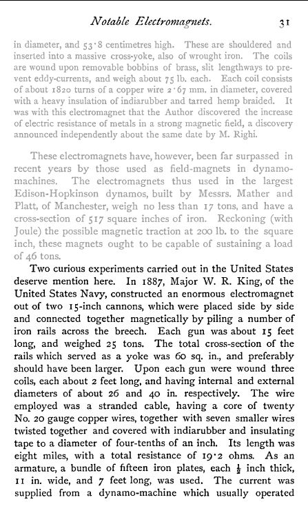
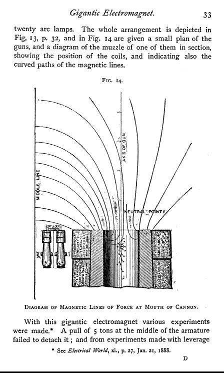
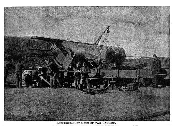
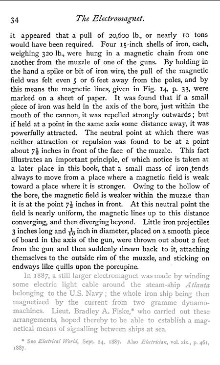
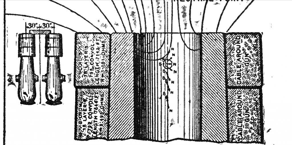
                      • I found this experiment interesting examining the neutral zone. Has anyone got a copy of the 1888 The Electrical World?:


                        Comment


                        • Sourcing material for build

                          I'm trying to locate materials to build the Hendershot device shown on PDF page 45 of "From The Archives Of Lester J. Hendershot".


                          I have some questions:
                          1. I'm not able to locate the dual 40-80 MFD, 450V caps so I'll just use separate caps with those ratings. Is that probably the reason that different photos show a different number of caps. I'm thinking the photos showing 3 caps are actually 3, 40 uF caps, with 2 in parallel to make the 80uF one. Is that right?

                          2. The drawing specifies "20 AWG Insulated Solid" for L1 and L2. Should these be copper? It doesn't say. Does anyone have insulated 20 AWG from the 50's or know where to find specs of that era? I'm wondering about the insulation thickness since it will affect the spacing between the wires. They didn't have the plastics back then that we have today so I'm wondering what the insulation was made of and how thick it was. I saw in one of the documents it was "Belden" wire and they still make it today but it uses plastic insulation. The reason I ask is that I recently replaced some wire going to a well pump that was installed in the mid 70's and it had some kind of rubber insulation and a #10 wire was roughly 1/4" outside diameter - much larger than today's plastic insulation.

                          3. Does anyone know specifically what type of material was used in the U shaped magnet , i.e. AlNiCo, Samarium Cobalt, etc? I saw somewhere that it was from a radar magnetron. Has anyone been able to confirm that it was or was not from a radar unit? That's an interesting question regarding LJH's working with the air force in the ealy days. Of course radar wasn't developed until the 40's but that is one of those coincidences that kind of jumps out at me.

                          4. Some drawings and photos show what appears to be a third pole in the middle of the magnet and some do not. Has anyone confirmed that one way or the other? I noticed in the photo of Mark Hendershot's magnet that it was different but then his device didn't work as far as I know.

                          5. Since today's iron mostly has some carbon in it I'm wondering if it would be better to use Paul Babcock's idea of using steel bird shot to make the iron bar or if anyone has a source for the kind of iron needed.

                          6. I'm looking for 30's, 40's, 50's telephones to get the ringer coils. Does anyone have a source for those parts or today's equivalent?

                          7. I saw the AHO notes about sealing the L4 cap-coil with parafin. Does that have any electret properties? I've seen electrects made of combinations of waxes over metal and was wondering if any of that info applies in the Hendershot device.

                          Any assistance/clarifications will be greatly appreciated.

                          Comment


                          • Originally posted by john_g View Post
                            I found this experiment interesting examining the neutral zone. Has anyone got a copy of the 1888 The Electrical World?:
                            Hi John, What a wonderful piece of electromagnet history you have there.
                            A cannon that would fire out small pieces of iron without need for explosives - 'hands-on' reporting !

                            You know – few people investigate beyond what they are shown/ taught, such that the majority who do not work hands-on with coils (and even many who do) still don’t realise that whilst the field within a standard spiral wound coil is more concentrated than the field outside of it, its polarity is also completely reversed.
                            Thus at the tubular ends of a spiral coil winding the field direction quite literally turns through 180 degrees around the end turns with respect to the coil axis !
                            Where does this leave those who merely draw imaginary field strength lines ?

                            The writer of that book used the same term as did Wesley Gary - neutral zone;
                            and yet in both field related examinations there were similar reactions due to iron being placed within a magnetic field.

                            There was not an axial 'neutral zone' generated by the cannon slightly out from its energised open end -
                            the still extremely powerful funnel shaped cannon field induced electron spin orbit alignments within the iron object in a non-linear manner.
                            This caused the object itself to develop a longitudinally differential field which enabled its resting in a position of minimum reactivity.

                            It was the resultant force which became neutral - not the cannon's field - and hence today I think that today we would not use that term neutral in the same way when discussing magnetic fields;
                            hence in that magnetised cannon field situation I think that words like minimum and null would be more appropriate.

                            Cheers .............. Graham.
                            Last edited by GSM; 10-30-2013, 09:22 AM.

                            Comment


                            • Originally posted by thx1138 View Post
                              I'm trying to locate materials to build the Hendershot device
                              Any assistance/clarifications will be greatly appreciated.
                              Much to discuss here, back shortly.

                              Cheers ................ Graham.

                              Comment


                              • Originally posted by GSM View Post
                                Hi John, What a wonderful piece of electromagnet history you have there.
                                A cannon that would fire out small pieces of iron without need for explosives - 'hands-on' reporting !

                                You know – few people investigate beyond what they are shown/ taught, such that the majority who do not work hands-on with coils (and even many who do) still don’t realise that whilst the field within a standard spiral wound coil is more concentrated than the field outside of it, its polarity is also completely reversed.
                                Thus at the tubular ends of a spiral coil winding the field direction quite literally turns through 180 degrees around the end turns with respect to the coil axis !
                                Where does this leave those who merely draw imaginary field strength lines ?

                                The writer of that book used the same term as did Wesley Gary - neutral zone;
                                and yet in both field related examinations there were similar reactions due to iron being placed within a magnetic field.

                                There was not an axial 'neutral zone' generated by the cannon slightly out from its energised open end -
                                the still extremely powerful funnel shaped cannon field induced electron spin orbit alignments within the iron object in a non-linear manner.
                                This caused the object itself to develop a longitudinally differential field which enabled its resting in a position of minimum reactivity.

                                It was the resultant force which became neutral - not the cannon's field - and hence today I think that today we would not use that term neutral in the same way when discussing magnetic fields;
                                hence in that magnetised cannon field situation I think that words like minimum and null would be more appropriate.

                                Cheers .............. Graham.
                                Graham

                                Thanks for that explanation. I have made an enlargement of the canon mouth area, as some details of the magnetic field alinement within the bore, did not show up well on the previous picture.

                                Regards

                                John

                                Comment

                                Working...
                                X