Part G
Really !
well apparently someone better tell my mentor that his part G is not suppose to work in his 2 year running 5 kilowatt device.
i'll be sure to tell him if i can get him to stop laughing so hard.
would you like to try again.
now that's funny.
MM
Announcement
Collapse
No announcement yet.
Re-Inventing The Wheel-Part1-Clemente_Figuera
Collapse
X
-
Originally posted by marathonman View Post
I noticed back in your post #1298 you wrote about your study of inductance. Very good. Because you rely on inductance and inductive reactance in your partG design, I suggest you take your studies further and learn about mutual inductance. Mutual inductance will have some influence on the primary coils but because they are on an open core, the coupling will be low to moderate. However on the toroid the coupling of coils will be nearly perfect, k = .98-.99.
When the wiper brush on the toroid winding is positioned at 12:00 noon or #8, and is connected to primary coil N passing maximum current that coil, it is also connected to the primary coil S via 2 halves of the toroid winding in parallel. On the surface, one would assume the reactance of the toroid coil will reduce the voltage at 6:00 or #1, the connection to primary coil S thereby allowing only a low current flow to it. However due to mutual inductance between the 2 halves of the toroid coil, the effective inductance of the toroid coil between 12:00 (8) and 6:00 (1) is essentially zero. Therefore the reactance of the toroid is just the resistance, which is very low. So the voltage difference between 8 and 1 is very small and the currents to primary N and to primary S are not too different.
I tried to explain this to Ufo in post #1260 but it flew past him. Maybe you'll pick up on it. But I don't think the use of a toroid in either method will yield the results you guys expect. But seldom is my advice taken, so I standby and see what develops.
Good luck,
bi
Leave a comment:
-
no train one engine
Ask hanon why it's derailed.
Only one proof of concept not two. my mentor has a complete working device as i will soon.
I know what part G is and how it operates, it's the rest that don't know and seams to not want to know.
the whole 1908 patent is worded as to describe the device in its lowest (elementary) form, many can NOT get past that and are stuck at face value.Last edited by marathonman; 10-13-2016, 05:47 PM.
Leave a comment:
-
-
Originally posted by hanon1492 View PostUfo,
Yes. Figuera filed 4 patents in 1902 which were sold in few days to a banking union. All those pdf files are in my site in spanish and translated into english. Long ago you already tested the patent#30376, if you remember. In those patents he used NS polarity and used intermitent or alternating current.
Later in 1908 he filed his last patent few days before dying. In this patent he changed the intermitent current or alternating to the use of the 2 unphased signals created by the rotary commutator, and he never stated explicitly the polarity. He just wrote: rectangles N and S but nothing about North or South, words that he never used. He left it open speaking from the legal part of the patent. He could have also said rectangle A and B, 1 and 2 which would be the same legally. I think it was a patent notation trick to avoid plagiarist while protecting legally the machine. Later Buforn in his 5 latest patents in 1910,1911,1912,1913 and 1914 did the same. Never explicit the polarity and just used the same notation of rectangle N and S. This is really weird in my view. 6 patents in all and no sentence stating the polarity explicitly.
Yes, I remember that...the only thing I did not have "clear" at that point in time, (not until I read Ken Wheeler's Book)...is that no matter if we use pulsed DC or AC sine wave...we should never allow to drop field(s) to zero...and that fact -considered a huge error- I believe was not allowing Us to reach the sky high outputs...
Originally posted by hanon1492 View PostMy tests: I tested the system as in the 1902 patent with pulsed DC and NS polarity and all I got was a common transformer with performance close to perfect, as normally expected.
When I tested the 1908 patent with unphased signals and NS polarity I got close to zero. Both electromagnets were inducing in contrary. But when I tested with NN I got easily 30% yield, unexpected at first, and some higher numbers, always below 100% so far. I just tested two sets and I think I need more sets all togethers. The weird results were with NN polarity. That why I bet for that.
Were you allowing Fields to collapse?...Or dropping signals to minus?
Originally posted by hanon1492 View PostAnyway, although I think that NN is the right polarity, I encourage everyone to build the system and test all possibilities and see: NN , NS, SS,.. it is a matter of flipping a couple of wires to test all polarities. The best is to test all possibulities and then measure and decide. But I continue supporting the NN polarity because it is the one which worked to MM, to his mentors, and to some spanish forum members.
Regards
I have conducted several testing with NN and SS in a different set up...but relating to generate an output on a secondary based on these repulsion fields...and I tell you something...when you "back and forth" a repulse field you will obtain an "h" signal where the straight and higher spike of the "h" would reverse in every change of direction. Although I have not tested this "reciprocating" (linear back-forth) movement at higher frequencies...I have done it by using only one direction (rotation) at high speeds and so the "h" signal is always increasing and never reversing, so output is evolving into very high values that depend on the speed your prime mover could deliver.
I have also used an N-N on one end of rotor, as an S-S Field across at 180º, which simulates the fast reciprocating reversal...and it is bad news...signals cancel at output.
But, like you are saying...we will have to test all possibilities with a full model built.
Thanks and Regards
UfopoliticsLast edited by Ufopolitics; 10-13-2016, 12:29 PM.
Leave a comment:
-
Originally posted by marathonman View Postbunch of bone heads.
i see your brain is getting in the way of a proper build.
Originally posted by Ufopolitics View Post"Sorry, but the more I read, the less I can find any place where it reads N and N', or S and S' but instead "rectangles N and S" through the whole patent."
oh yeh, i have all been lying to everyone and my 10's of thousands of hours of research was all in vein. f-in please, give me a f-in break.
the intelligence level just dropped 20 points on this thread and i am growing tired of unintelligent closed minded individuals.
for future reference please pull you heads out of your asses and use your brain for more then an ass hat.
if i wanted this stupidity i would of went back to OU. sorry Doug.
MM
But take it easy friend, take something, whatever and relax...
It has taken me over 1300 posts to build several machines and conduct several experiments on this forum, every one, backed up by many, many videos still available on my you tube chanel...
At any point I have mentioned on that post above (directed to Hanon) that I do not believe that a N-N or a S-S would not work. I was the first here to say that a repulsion field would work.
It was just my opinion and question based on what I have read from the original patents, in their original language.
Between a Repulsion or an Attraction Primary Exciting Field ...which one would work better in order to produce-generate a higher final output result...is just "four bolts away" in my set up, to reverse both primaries and check which one of the two fields would work better as generating much higher output...and that would be the one and only thing that would dictate the way I would be reproducing the rest of the "Figuera Modules"...no matter how much anyone here scream, jump or cry... trying to change methods, it won't happen, not on my end.
By the way, I have thought about another way, regardless of which field (repulse or attract) and that has to do with the iron core design between primaries and secondaries...but I still have to make it happen and then check it out to conclude if it would or would not work better...still on my mind. But I believe it would amplify output even more. Again, I could be right or wrong...only testing would tell me the answer.
Regards and let's relax a bit...there is no way to be able to work "patiently" in an "altered" state of mind...
UfopoliticsLast edited by Ufopolitics; 10-13-2016, 12:28 PM.
Leave a comment:
-
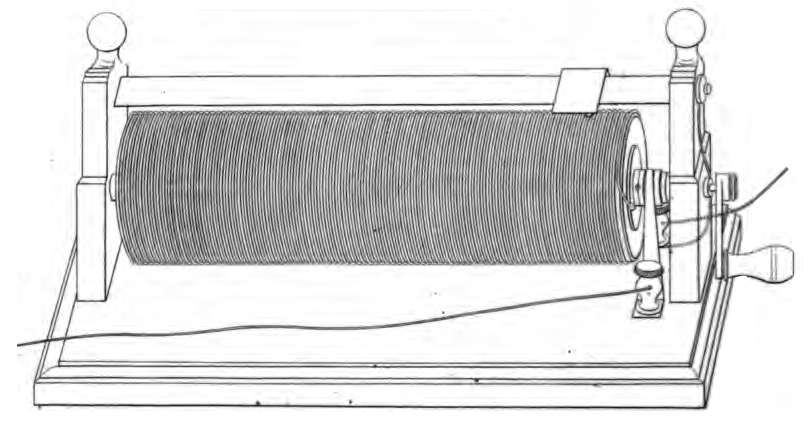
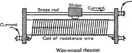
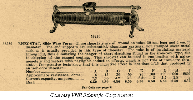
I post below the images of some rheostats from the beginning of 20th century or last part of the 19th century.
You can compare them with the patent. Although beeing rheostats to change the ohmic resistance they were built as coiled wire.
Last edited by hanon1492; 10-13-2016, 11:47 AM.
Leave a comment:
-
Ufo,
Yes. Figuera filed 4 patents in 1902 which were sold in few days to a banking union. All those pdf files are in my site in spanish and translated into english. Long ago you already tested the patent#30376, if you remember. In those patents he used NS polarity and used intermitent or alternating current.
Later in 1908 he filed his last patent few days before dying. In this patent he changed the intermitent current or alternating to the use of the 2 unphased signals created by the rotary commutator, and he never stated explicitly the polarity. I can not explain the difference between 1902 and 1908 patents. In 1908 he never stated the polarity, he just wrote: rectangles N and S but nothing about North or South, words that he never used. He left it open speaking from the legal part of the patent. He could have also said rectangle A and B, 1 and 2 which would be the same legally. I think it was a patent notation trick to avoid plagiarist while protecting legally the machine. Later Buforn in his 5 latest patents in 1910,1911,1912,1913 and 1914 did the same. Never explicit the polarity and just used the same notation of rectangle N and S. This is really weird in my view. 6 patents in all and no sentence stating the polarity explicitly.
My tests: I tested the system as in the 1902 patent with pulsed DC and NS polarity and allI got was a common transformer with performance close to perfect, as normally expected.
When I tested the 1908 patent with unphased signals and NS polarity I got close to zero. Both electromagnets were inducing in contrary. But when I tested with NN I got easily 30% yield, unexpected at first, and some higher numbers, always below 100% so far. I just tested two sets and I think I need more sets all togethers. The weird results were with NN polarity. That why I bet for that.
Anyway, although I think that NN is the right polarity, I encourage everyone to build the system and test all possibilities and see: NN , NS, SS,.. it is a matter of flipping a couple of wires to test all polarities. The best is to test all possibulities and then measure and decide. But I continue supporting the NN polarity because it is the one which worked to MM, to his mentor, and to some spanish forum members.
RegardsLast edited by hanon1492; 10-13-2016, 12:09 PM.
Leave a comment:
-
Quote;
"By the way as far as I know you dont have yet a working toroid part G."
There you go again, your brain getting in the way, typical Hanon running his mouth with no facts to back it up.
Mm
Leave a comment:
-
Originally posted by marathonman View Postbunch of bone heads.
i see your brain is getting in the way of a proper build.
Quote;
"Sorry, but the more I read, the less I can find any place where it reads N and N', or S and S' but instead "rectangles N and S" through the whole patent."
and it's taken you 1300 plus post to realize this. good god dude what are you smoking???
oh yeh, i have all been lying to everyone and my 10's of thousands of hours of research was all in vein. f-in please, give me a f-in break.
the intelligence level just dropped 20 points on this thread and i am growing tired of unintelligent closed minded individuals.
for future reference please pull you heads out of your asses and use your brain for more then an ass hat.
if i wanted this stupidity i would of went back to OU. sorry Doug.
Quote;
"Well we can see that the toroid is going to be difficult to tune, especially in the case of a rotary brush touching sequentially turn to increase/decrease the inductance. Your choice... Tune= Wind + Test + Rewind to adjust the proper number of turns required"
and this of course coming from an expert builder that has built many, many things, part G's and of course you got this graph from a real part G. please by all means don't let me get in the way of your BRAIN getting in the way.
i think from now on i will just watch the morons trip on their shoe laces and laugh at the stumbling as it is quite entertaining .
MM
By the way as far as I know you dont have yet a working toroid part G. First built it, and later tell how to do it and how to operate it.
You have to realize that here people need a simple device as proof of principle. If successful later they will upgrade it for better performance, as you intent with the toroid.
Besides our difference I hope to see you in the forum. We have a common goal : Figuera . I will love really to see you here or in OU and see you sharing your succedding. Then you can insult us and those insult will be the best I could ever listen, because I will really happy
Leave a comment:
-
Ignorance
bunch of bone heads.
i see your brain is getting in the way of a proper build.
Quote;
"Sorry, but the more I read, the less I can find any place where it reads N and N', or S and S' but instead "rectangles N and S" through the whole patent."
and it's taken you 1300 plus post to realize this. good god dude what are you smoking???
oh yeh, i have all been lying to everyone and my 10's of thousands of hours of research was all in vein. f-in please, give me a f-in break.
the intelligence level just dropped 20 points on this thread and i am growing tired of unintelligent closed minded individuals.
for future reference please pull you heads out of your asses and use your brain for more then an ass hat.
if i wanted this stupidity i would of went back to OU. sorry Doug.
Quote;
"Well we can see that the toroid is going to be difficult to tune, especially in the case of a rotary brush touching sequentially turn to increase/decrease the inductance. Your choice... Tune= Wind + Test + Rewind to adjust the proper number of turns required"
and this of course coming from an expert builder that has built many, many things, part G's and of course you got this graph from a real part G. please by all means don't let me get in the way of your BRAIN getting in the way.
i think from now on i will just watch the morons trip on their shoe laces and laugh at the stumbling as it is quite entertaining .
MMLast edited by marathonman; 10-13-2016, 10:44 AM.
Leave a comment:
-
@Hanon
Hanon,
I have some doubts about Figuera's Later Two Patents...
I am very familiar with the 1908 that you have on your site...however, I have found a former one (1902) which is basically the same exact thing, except there is much more detailed explanations about His set up...
The Spanish reference site where I have found it, is below:
FIGUERA'S PATENTS
And the basic issue I have found on this earlier patent is quoted in a short fragment below, so please refer precisely to my underlined and bold sentences:
El procedimiento queda, pues, reducido a establecer un circuito inducido independiente, dentro de la esfera de acción o atmósfera magnética formada entre las caras polares, de nombre contrario, de dos electroimanes, o series de electroimanes, accionados por corrientes intermitentes o alternas.
Therefore, the procedure is reduced to set an independent induced circuit, within the sphere of action or magnetic atmosphere conformed by the polarity faces of opposite names, from two electromagnets or series of electromagnets, activated by intermittent or alternative currents.
So, I understand by two magnetic polarity faces of "opposite names" as "alike" poles...plain and simple, which means North and South.
Now, could you please show me where it is written (in the Spanish Patent from 1908) about "like" poles facing each others as the Inducing electromagnets?
Sorry, but the more I read, the less I can find any place where it reads N and N', or S and S' but instead "rectangles N and S" through the whole patent.
You also have that Patent from 1902 (#30375) in your website here
Thanks in advance
Regards
Ufopolitics
Leave a comment:
-
Originally posted by seaad View PostWoW! Hanon. What a picture! Are you a teacher?
Arne
Leave a comment:
Leave a comment: