Announcement

Collapse
No announcement yet.

Re-Inventing The Wheel-Part1-Clemente_Figuera

Collapse
X
 
  • Filter
  • Time
  • Show
Clear All
new posts

  • marathonman
    replied
    Spin Direction

    It is Exactly the same thing. the two bar magnetic fields are opposing and if one is pushed farther away from the wire, is exactly the same as an electromagnet's currant being reduced. one magnet is brought closer while the other farther away in unison.

    I'm not trying to sound rude but is this your dogma taught brain talking or is it your research talking because they are two entirely different things.
    not only does the patent say they are opposing, William Hopper proved it with opposing fields but my OWN research proved it to be so.
    i have thousands upon thousands of hours of research into the Figuera Device and it's function and there is not one person in this forum that can make me think other wise.

    the observed spin directions alone prove i am right as a North/South electromagnet set up has opposing induced in the Figuera device and North/North set up has induced in the same direction supporting one another. i would suggest you dig a little deeper into spin directions and the Figuera device before you bring a sponge cake to a knife fight.
    Metaphorically speaking of course, no disrespect intended.
    please study spin directions and pic.


    MM
    Attached Files
    Last edited by marathonman; 09-07-2016, 06:48 PM.

    Leave a comment:


  • Mario
    replied
    Originally posted by marathonman View Post
    the PDF is William Hooper's work on motional Electric fields. skip to his test he did with magnets chapter 7 if you want, but it's all good research. his test with magnets are exactly what is happening in the Figuera device.MM
    Hi MM,

    to me it doesn't seem to be the exact same thing? You said in the CF device there are opposing magnet poles, while one is increasing the other is receding, in unison.
    The experiment in the book describes 2 parallel bar magnets which, when moved away simultaneously in opposite directions from the wire placed in the centre, will induce a current in the wire. This is not what is supposedly happening in the CF device. If we were to do the same process in the CF device, meaning increase and decrease the 2 opposing primaries in sync, we wouldn't get anything in the secondary coil.

    Mario

    Leave a comment:


  • marathonman
    replied
    Oh, well please enlighten us with math hanon.
    granted not complete but not wrong.
    the 14.8 lbs force or what force you are dealing with is what the secondary sees , the primaries have to be calculated from that point.
    the end result is lbs force per kilowatt.

    but by all means show us with examples.
    Last edited by marathonman; 09-06-2016, 08:04 PM.

    Leave a comment:


  • hanon1492
    replied
    Originally posted by marathonman View Post
    it takes 14.8 lbs force shifted back and forth for every kilowatt of power produced so at 15 kilowatt that is 222 lbs force devided by how ever many cores you have
    Hi,
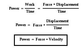
    To compute the power you need to know the force and the velocity of the magnetic lines moving along the induced coil back and forth. So for example for 60 Hz inducer frequency and a induced coil length of L inches and supposing that the magnetic lines move along the whole coil length one way and the way back in every cycle, then each second you have a movement of 2•L•60 inches/sec. Therefore that force is related to power for certain frequency and for certain induced coil length.


    Power = Force • Velocity


    Last edited by hanon1492; 09-07-2016, 12:31 AM. Reason: Added relation to frequency and coil length

    Leave a comment:


  • marathonman
    replied
    Research

    The best thing for someone to do is read my synopsis post 873, read all the patents and watch Hanon's video on the shifting of the opposing fields.
    with those items in your mind you will get a good mental picture of what is going on with the Figuera device. from there you can read William Hooper's great take on Motional Electric fields and his excellent description of what is happening in the Figuera device. it took 70 years for some to figure this out, WOW !

    the PDF is William Hooper's work on motional Electric fields. skip to his test he did with magnets chapter 7 if you want, but it's all good research. his test with magnets are exactly what is happening in the Figuera device.

    elcheapo; you have to have currant change in order for the Figuera device to work. you stated that voltage and currant didn't change, i thought this is how CF mitigated lentz, he changed intensity of the currant with part G and used two opposing electromagnets that has no drag. every one is to occupied with lentz when other things are more important.

    MM
    Attached Files
    Last edited by marathonman; 09-06-2016, 08:11 PM.

    Leave a comment:


  • marathonman
    replied
    Quote; "I understand very clear the way you are seeing this patent, and honestly I believe you are actually improving it by "recycling" the energy back to the inductors on the "R" box, making Part G also a source...since Figuera states this feed comes from an External Source (written "foreign" in the patent translation)."

    I wish UFO but no, i just interpret what i see, it is all Figuera's genius not mine. it took me three years and the help of a colleague to figure out Figuera's genius device.
    i agree your bolded paragraph is one of the essential elements of the Figuera device. the statement in the patent saying "any variation will produce currant flow", while being true, is not completely true for the Figuera device. he then states "an orderly fashion" which is entirely correct. if the two electromagnets are not in complete unison all induction will drop to the peak of the rising electromagnet. this very statement i just made has been verified by my own research. so the best and easiest way to accomplish this feat is to wind a core in a variac fashion allowing both feeds to be varied in unison.

    referring to the coils, one should wind the primaries with as little self inductance as possible. the reason for this is if the primaries have high self inductance, the coils will take to long to respond to currant change. on the other hand if the coils are wound with a little thicker wire, fewer winding's and use a little more currant, the coils will have low self inductance therefore respond much quicker to currant changes. also with fewer winding's comes less resistance in which is a good thing.
    something to keep fresh in your mind is part G controls the currant at all times not the primaries, so when constructing part G remember all power supplies are built to handle the load plus extra head room, meaning use thicker wire on part G then your primaries coils have.
    plus your core of part G has to handle more watts then supplying the primaries, example;
    lets say your part G is wound to put out 100 volts at 5 amp peak for the increasing electromagnet and 2.5 amp for the decreasing electromagnet. that is 7.5 amp at 100 volts = 750 watts of power. i myself would have a part G core of no less than 1250 va rating at minimum and would probably use 1500 to 2000 va rated core. always give your self extra head room.
    your part G will become the power supply when started and power supply removed so keep this in mind when constructing part G.

    this is just a guide line when constructing your device, each device might use a little more currant while others might use less currant. the final specs will be up to the builder what he feels comfortable with.
    it takes 14.8 lbs force shifted back and forth for every kilowatt of power produced so at 15 kilowatt that is 222 lbs force devided by how ever many cores you have or what force you feel comfortable in dealing with. that 222 lbs can be split between 7, 8, 10, or even 12 or more, it is all up to you.
    another thing to remember is each primary has to handle 1/2 of the secondary output example, lets say 222 lbs devided by say 8 cores is 27.75 lbs force per core shifted back and forth so each primary is accountable for 13.875 lbs force. so wind your primaries to produce 13.875 lbs force or what ever your goal may be.

    MM
    Last edited by marathonman; 09-06-2016, 02:43 PM.

    Leave a comment:


  • Ufopolitics
    replied
    Coils Specīs...

    Originally posted by Turion
    What we are lacking here are the specifics of the "Best" coil that will act as the two electromagnets and the "Best" coil to place in the generator position. If anybody has THAT information, it would be greatly appreciated. I believe there is plenty of research that will need to be done to determine the best two coils to use, and to me that it a first step.

    Dave
    Dave,


    As in any Exciter-Generator arrangement, the Inducing coils (Exciters) should be done with finer wire, multifilar if possible to magnify magnetic field, higher resistance, so, many turns, in order to be fed with lower voltage-amperage.

    The Generating Coils (Secondary) should be the opposite, higher gauge and lesser turns, lower resistance, etc.

    The "very" specifics on the exciting coils are dictated EXACTLY by the power supply you would be using (Ohms Laws).

    Tesla recommended this same spec's on his generators patents, as he cited "coarse" as higher gauge and "finer" for smaller gauge.

    Only real building and testing will give you the exact number of turns as the size of the appropriate ferromagnetic cores.


    Hope this helps you.


    Regards


    Ufopolitics
    Last edited by Ufopolitics; 09-06-2016, 12:34 PM.

    Leave a comment:


  • BroMikey
    replied
    Originally posted by marathonman View Post
    again i thank you for your post but i think newcomers are being
    confused at the notion of resistors in this device

    BroMikey; two opposing magnet or electromagnet's will always
    put out more than a single one will. Walter Russel stated our coils
    are wound wrong, wasting 50 % E field to magnetism. Figuera
    figured out how to add that lost 50 % back making it 100 %.
    no standard generator can touch this level.

    PS. if not in opposing mode ie. N/N or S/S double intensity E fields
    will not form. if using N/S the currants will buck each other and
    output will be less than half of the previous stated.
    I am still trying to comprehend your thesis. But thanks 4 the simple
    version. I like the easy versions first and repeated. That PJK stuff
    is often messed up totally. It's better than a 6th grader with a crayon.

    I have found many details worst than the Patents that threw me for
    a loop, but Patrick did the best he could having to many to post.

    I am watching for an experiment so I can do it here.
    Last edited by BroMikey; 09-06-2016, 02:11 AM.

    Leave a comment:


  • hanon1492
    replied
    Originally posted by kEhYo77 View Post
    Hanon, are you 101% sure that this is the case with N and S poles being wrong? I know the patent says that it is a simplified drawing.
    To me the whole drawing looks more and more like rectangular coils from top view. The wires touch to those rectangular lines and in the center of each coil there is an indication of what magnetic field of that coil is facing the top, the bottom is hidden and is opposite. Also, it look to me that the resistor array part might have been a cylindrical, cored inductor consisting many turns between taps and working as a variable choke. I'll try to check something similar on my setup.
    I am not trying to sway you or anything, I'm just seeing what I see.
    Hi Kehyo,

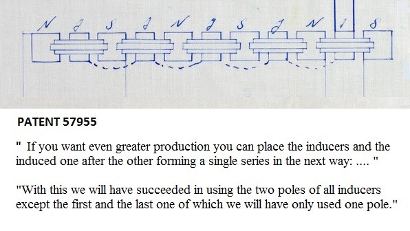
    At the beginning I thought the same as you. But later studying the 5 patents filed by Buforn, Figuera's partner, after 1908 when Figuera died, I realized that they tried to used straight coes, especially this is seen in the 1914 patent when Buforn piled many electromagnets and coils in order to use BOTH poles of each electromagnet while the basic design just uses one pole. Please study this page:

    https://figueragenerator.wordpress.c...orn-post-1908/


    But again I repeat that the secret is to use both electromagnets in repulsion: North-North or South-South.

    North-South will not work. I explain it in this very important link https://figueragenerator.wordpress.c...nterpretation/
    Last edited by hanon1492; 09-06-2016, 12:50 AM.

    Leave a comment:


  • Elcheapo
    replied
    Control Circuit

    Hi Gang.

    Would just like to share some of my work with everybody.

    Being in electronics all my life, I thought I'd try out a solid state circuit for the C.F. device.
    I'm pulsing a cd4029 counter with a 555 chip. This counter is bi-directional so I set it up to count
    from 1 to 8 in sequence and then keep reversing at the end of each count.
    For each of the 8 counts I have two 500 ohm pots connected in parallel across a 12 volt line. One pot to set the gate
    voltage of mosfet A. And one to set the voltage of mosfet B. These power fets sets the amperage levels of coils A & B.
    So for 8 pulses we need 16 pots. We can't just wire all these pots to the gates all together.We have to isolate them
    some way so that each adjustment is independent of all others. The circuit I use consists of one 2n222 transistor
    and 3 pc817 opto-couplers which are all used as electronic switches.
    A positive going pulse from the counter turns on the 2n222 which then turns on (or off) all 3 opto-couplers.
    The 3 coupler led's are connected in series across a 5 volt line controlled by opto 1. When the led turns on, the emitter-collector junction then conducts.
    One of these junctions turns the 12 volts to the 2 pots either on or off.
    The other 2 couplers controls the adjusted voltage to the 2 mosfets. So the gate of each mosfet has 8 wires going to it
    with only one wire at a time being active. We need 8 of these circuits to do the job.
    Using an ammeter in the drain line I adjusted the pots like so: Coil A: 9,8,7,6,5,4,3,2 amps. Coil B :2,3,4,5,6,7,8,9 amps.
    With the circuit turned on, total current drain was 11 amps which is the difference between the 2 coils.
    So with this setting, the source voltage and amperage never change. I thought this was how C.F. mitigated the Lenz effect.
    But when measuring the secondary voltage all I got was a big zero. Oh I could measure some by unbalancing the circuit.
    Tried exchanging wires on one of the primaries but still zero.
    Because of this complete voltage cancellation, I think the coil placement is all wrong. CF said that the secondary coil
    should be between the 2 primaries. But that could be either parallel or perpendicular.
    I, like many others on here are using "C" sections from old transformers for the core. The magnetic field is closely
    contained within such structures. CF definitely said that this is NOT a transformer.
    If we are trying to extract energy from the environment by using a varying magnetic field, then it stands to reason
    that the magnetic field should have as much exposure to the environment as possible.
    I therefore think that all coils wound on a straight core is the way to go.
    Hanon has some very good posts on this subject, so I'll be doing a lot of reading before going any further.

    Leave a comment:


  • Ufopolitics
    replied
    Originally posted by Wistiti View Post
    UFO, my point with the bucking field is it will negate the lenz effect..
    It is the way i see it but as i have said before, testing will reveal the truth! And dont worry it also goes for me! I will try it soon. 👍
    Anyway, lets share our result! 😊

    Wistiti,

    I LOVE REPULSION (Bucking) FIELDS, my Friend!!

    I have made a Generator which only works based on Repulsion Fields...

    And so, I do agree they are MUCH BETTER than Attract Fields.


    Regards


    Ufopolitics

    Leave a comment:


  • Ufopolitics
    replied
    Thanks MM

    Originally posted by marathonman View Post
    Ufopolitics;

    Yes sir i do and thank you kindly.

    "BUT", if i may add, that the commutator bars and resistor referred to in the patent are actually thick winding's on a core. it says it is, in it's elementary form for understanding and is just a drawing.
    i think people are getting confused as the term resistors being referred to on a continuous basis. PJK even states in his book and this incorrect assumption is confusing people when they come here.
    part G is actually both in the drawing in its higher form and has many functions, that is why part G can NOT be omitted or replaced.

    1. it split the DC currant into two separate feeds.

    2. each feed has opposing fields allowing each feed to be varied separately in unison.

    3. allows the inductive force from the declining electromagnet being shoved out of the secondary core into it's own core, then to be stored in the core of part G like an inductor to be used at the next half rotation. part G is constantly fed from all declining electromagnets every half turn of the brush.

    4. becomes the power supply for the entire system after initial start.

    as you can see part G is very valuable to the Figuera device.
    also as you might gather part G does not have a lot of winding like a regular variac. in Hanon's video he used a variac with DC and verified this as only a 1/4 turn varied the currant from zero to full.

    again i thank you for your post but i think newcomers are being confused at the notion of resistors in this device.

    BroMikey; two opposing magnet or electromagnet's will always put out more than a single one will. Walter Russel stated our coils are wound wrong, wasting 50 % E field to magnetism. Figuera figured out how to add that lost 50 % back making it 100 %. no standard generator can touch this level.

    PS. if not in opposing mode ie. N/N or S/S double intensity E fields will not form. if using N/S the currants will buck each other and output will be less than half of the previous stated.
    Thanks MarathonMan,


    I really hate to disagree with you about the Resistors part...it is stated as "Resistencia" which means Resistance...then the "R" inside the box stands for Resistors Box. This way a variation in the positive feed will cause different levels of Field Intensities across both Primary Coils.

    However, I agree it is just a drawing...and even if they were resistors...are not "represented" properly as a real resistor symbol...and look more like small coils.

    But, anyways even being coils and cores acting as inductors, like you have interpreted, they will still add a variable resistance feed, just like you wrote, splitting the high end feed in two.

    I understand very clear the way you are seeing this patent, and honestly I believe you are actually improving it by "recycling" the energy back to the inductors on the "R" box, making Part G also a source...since Figuera states this feed comes from an External Source (written "foreign" in the patent translation).

    The main point and reason why I have posted here is not about the discussion on each particular detail about this specific patent...but mainly to make everyone notice that Figuera emphasizes very clear about his device Moving the Virtual Magnetic Fields in-out of the Induced (secondary) coils and cores, producing currents, while all Coils and Cores generating the Magnetic Fields to do the excitement at the Induced (secondary) are ALL completely static.

    I have also some other disagreements about N-S and N-N differences,... but I will not post them here as I consider they are off topic, as could create confusion...so, by no means I want to interrupt your excellent work here.

    You understand perfectly clear the statement above in bold letters, and that to me is the most essential part, which reinforces my work.

    Please keep posting all your work as I will be just watching...


    Thanks again and kind regards


    Ufopolitics
    Last edited by Ufopolitics; 09-05-2016, 10:15 PM.

    Leave a comment:


  • Wistiti
    replied
    UFO, my point with the bucking field is it will negate the lenz effect..
    It is the way i see it but as i have said before, testing will reveal the truth! And dont worry it also goes for me! I will try it soon. 👍
    Anyway, lets share our result! 😊

    Leave a comment:


  • marathonman
    replied
    resistors

    Ufopolitics;

    Yes sir i do and thank you kindly.

    "BUT", if i may add, that the commutator bars and resistor referred to in the patent are actually thick winding's on a core. it says it is, in it's elementary form for understanding and is just a drawing.
    i think people are getting confused as the term resistors being referred to on a continuous basis. PJK even states in his book and this incorrect assumption is confusing people when they come here.
    part G is actually both in the drawing in its higher form and has many functions, that is why part G can NOT be omitted or replaced.

    1. it split the DC currant into two separate feeds.

    2. each feed has opposing fields allowing each feed to be varied separately in unison.

    3. allows the inductive force from the declining electromagnet being shoved out of the secondary core into it's own core, then to be stored in the core of part G like an inductor to be used at the next half rotation. part G is constantly fed from all declining electromagnets every half turn of the brush.

    4. becomes the power supply for the entire system after initial start.

    as you can see part G is very valuable to the Figuera device.
    also as you might gather part G does not have a lot of winding like a regular variac. in Hanon's video he used a variac with DC and verified this as only a 1/4 turn varied the currant from zero to full.

    again i thank you for your post but i think newcomers are being confused at the notion of resistors in this device.

    BroMikey; two opposing magnet or electromagnet's will always put out more than a single one will. Walter Russel stated our coils are wound wrong, wasting 50 % E field to magnetism. Figuera figured out how to add that lost 50 % back making it 100 %. no standard generator can touch this level.

    PS. if not in opposing mode ie. N/N or S/S double intensity E fields will not form. if using N/S the currants will oppose each other and output will be less than half of the previous stated.
    Last edited by marathonman; 09-08-2016, 05:34 AM.

    Leave a comment:


  • Wistiti
    replied
    I think the polarity of the primary field really mathers... It must always be in
    Bucking ... Test it, i think it is the best way to see it! 😉

    Leave a comment:

Working...
X