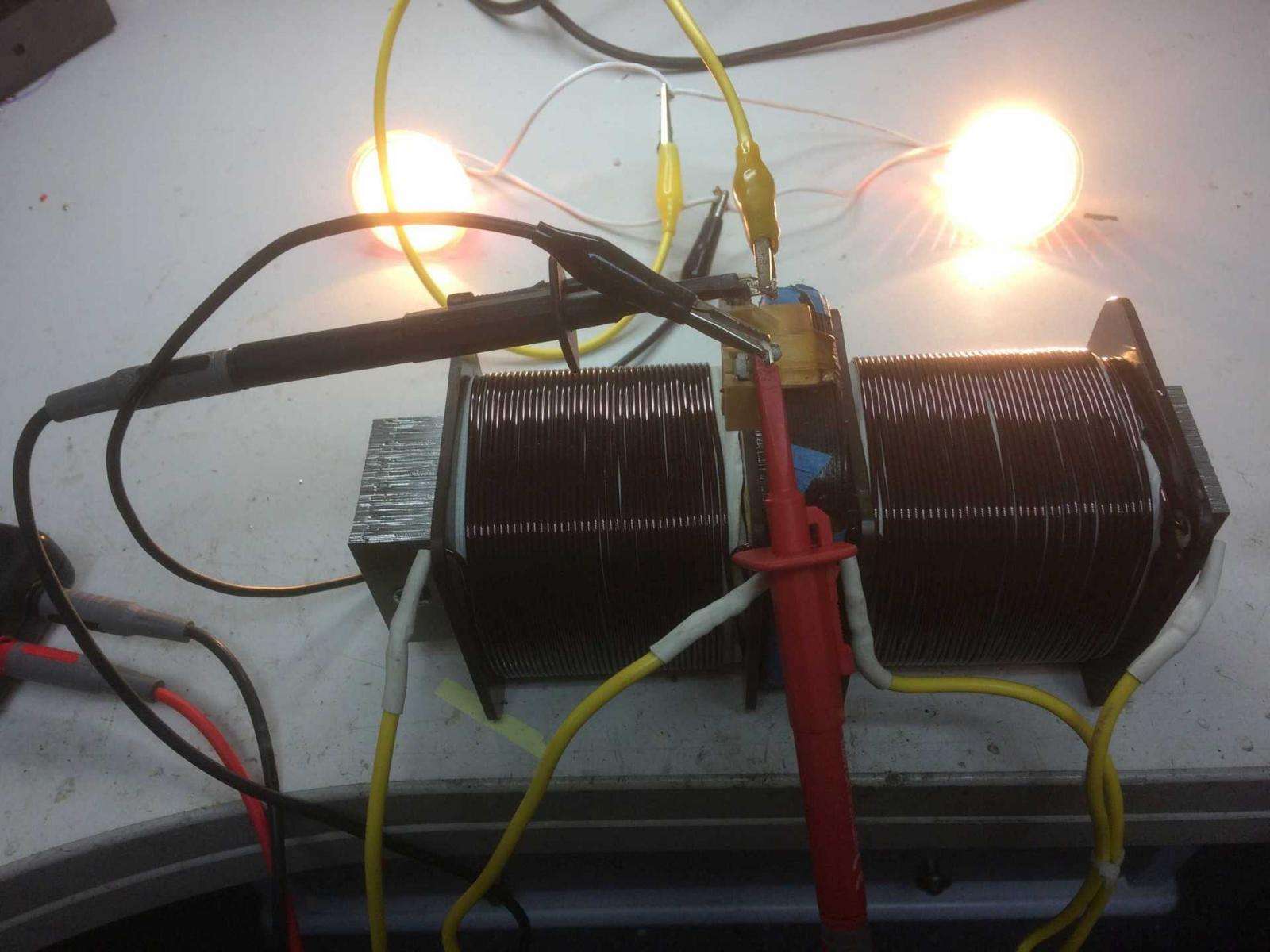
V & I on scope
Hi Ufo,
Here's a diagram:

So channel A is current (measuring millivolts across the shunt) and channel B is voltage. The source, represented by the circle with sinewave in that diagram, is your power supply (PSU). The ground is the PSU negative terminal. Ground is common between channels A & B.
If for your test condition the scope shows straight lines (DC) then note the magnitude and check against digital meters on the PSU. If those match then you can move the scope to the output and do a similar measurement.
Hope that clears it up.
bi
Originally posted by Ufopolitics
View Post
Here's a diagram:
So channel A is current (measuring millivolts across the shunt) and channel B is voltage. The source, represented by the circle with sinewave in that diagram, is your power supply (PSU). The ground is the PSU negative terminal. Ground is common between channels A & B.
If for your test condition the scope shows straight lines (DC) then note the magnitude and check against digital meters on the PSU. If those match then you can move the scope to the output and do a similar measurement.
Hope that clears it up.
bi


 capisci?


Comment