Announcement

Collapse
No announcement yet.

Re-Inventing The Wheel-Part1-Clemente_Figuera

Collapse
X
 
  • Filter
  • Time
  • Show
Clear All
new posts

  • Magnetic Amplifier to create two unphased signals

    Hi all,

    I am pretty sure that with a magnetic amplifier (saturable reactor) we can get the two opposite signals needed for the Figuera´s 1908 patent. For example: an audio amplifier (push-pull) may be implemented with a magnetic amplifier.

    Idea: use a rectified AC signal as input to a magnetic amplifier in order to regulate the output signal with negative feedback, (negative gain) so that an increase in the input will make a decrease in the output (see attached sketch)

    Some important facts about mag amp:

    "The magnetic amplifier, like the vacuum tube and the transistor, is an electrical control valve where a smaller current controls another circuit´s larger current"

    "With a magnetic amplifier you can control AC load current only. For DC applications it is possible to control an AC current and rectify the output"

    "Magnetic amplifer control circuits should accept AC input signals as well as DC input signals. The DC input signal is called "bias". The most effective way to apply bias to a saturable core and also allow AC input signals to control the magnetic amplifier is to use a bias winding"

    I attach an schematic to clarify this idea. The schematic is just to show the main idea. It is not a working design because I am not an expert (maybe someone more skillfull into mag amps may design a working device...). The main advantage is that this will be a very easy implementation. Any expert around here?


    Magnetic Amplifier Overview (Trinkaus,2006)

    Magnetic Amplifier (link 1)

    Magnetic amplifier (link 2)

    Magnetic Ampifier (link 3)

    Magnetic Amplifier (link 4)

    Directory with some books

    Regards
    Last edited by hanon1492; 01-15-2014, 12:00 AM.
    https://figueragenerator.wordpress.com/

    Comment


    • serialisation

      As was established, transformer action, i.e. the power output of a transformer depends on the change of the magnetic field strength.

      The following is a quote from Duncan's document http://dnp.s3.amazonaws.com/b/b5/Dun...20doughnut.pdf
      The Basic formula for the magnetic field strength in a core is as shown here
      H= 0.4 x Π x N x I ÷ ℓ

      Where
      H = magnetic field strength in oersted
      N = number of turns
      I = DC current in Ampere [A]
      Π = pi = 3,14....
      ℓ = mean magnetic path length in centimeter [cm]

      Now let me ask you a question do you see voltage or power involved in that formula at all ?
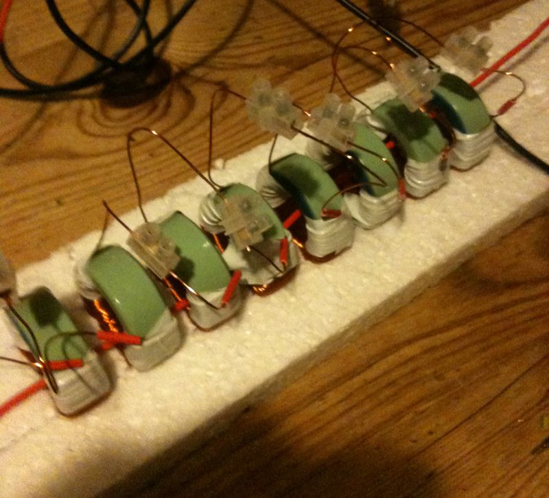
      Keep this in mind when looking at the serialized wiring of the transformer-generators at the bottom of this image by Arto Heino http://artojheino.yolasite.com/resou...lement66b2.jpg
      All the individual primaries of the transformers are connected in series.
      That means that in the Figuera-commutator only one pair of brushes is used and these two brushes supply the signal to all the transformer primaries.

      Why are there so many primaries? And why are they connected in series? Why not just one transformer?

      It is because the (change of) Amps generates the output. And the Amps can be reused and it does not matter how many coils you put in series, they will all get the full amount of current and they will all generate the full magnetic field strength, regardless of the fact that the voltage gets divided in a serial setup.
      Imagine several watermills along the course of a water conductor i.e. river. Serialized mills which will all receive the same amount of water (current). More watermills along the river, more energy.

      So a Figuera setup with just one transformer will not give you overunity, but the serialization of several of his transformer-generators will.

      I guess my main message is: Do not try with only one transformer.
      Two transformers: double output.
      Last edited by marxist; 01-16-2014, 01:59 PM.

      Comment


      • Ignoring something

        Hi marxist,

        Duncan in his overly simplistic view is ignoring a well known fact. If you double the number of turns in order to double the flux (field strength) you also have to double the input voltage to maintain the same current as you had before. It is true the current times the turns is all you need to calculate the strength of the flux but the current is directly dependent upon the voltage applied to the coil.

        Respectfully, Carroll
        Just because someone disagrees with you does NOT make them your enemy. We can disagree without attacking someone.

        Comment


        • exactly

          Hi Carroll,
          Originally posted by citfta View Post
          ...If you double the number of turns in order to double the flux (field strength) you also have to double the input voltage to maintain the same current as you had before. ...
          This is correct and it contains the answer to the question:
          Originally posted by marxist View Post
          Why are there so many primaries [in Figuera's desigh]? And why are they connected in series? Why not just one transformer?
          Keeping the content of your post in mind, I think this can be answered as follows:
          Instead of having just one transformer and putting more turns on its primary coils - which is counter-productive, as you point out - it is beneficial to use a great number of serialized low impedance primary coils of independent transformers.

          If one follows this design each individual primary is operating at (relatively) low voltage but full Amperage, generating maximum flux change.
          The output of all these transformers will be additive, avoiding the need to increase turns per coil.
          Last edited by marxist; 01-17-2014, 09:46 AM.

          Comment


          • Hi,

            The use of a high number of turns per coil may be ineffective because once the electromagnet reaches its saturation point there won´t be any increment in the magnetic field. Therefore instead of using one electromagnets with 7•N coils well above its saturation it would be better to used 7 electromagnets with N coils and keep each one below the saturation point. If you use thick wire then the resistance will be low and the power used will be very low (apart from the heat dissipated in the resistor)

            As with batteries, if you join them in series you would be increasing the output voltage. If each stage gives 15-20 volts then the seven stages will give 110 volts, which was the standard in the Spanish electrical network in that time. In my view, each stage should be overunity but the overall device was designed to reach 110 volts and have a sinusoidal shape (with the use of the conmutator and the resistors) in order to use the output current in the electrical network for any kind of motor or appliance.

            Regards
            https://figueragenerator.wordpress.com/

            Comment


            • As far as DC resistance goes it doesn't matter if you put all the wire on one big
              core or use many small cores with less wire in series. When you add coils in
              series the DC resistance is added together so more voltage is required to
              produce more current.

              Voltage is not in the formula for magnetic field strength because it doesn't need to be.

              Just to show it's not all about magnetic field "strength". We have a list of properties and terms to describe them.

              Some of the other important factors are

              1) Magnetic flux. Total Magnetism

              2) Flux density. The concentration of the flux within a certain area.

              3) Flux linkage. How well the flux from one winding links to the other/s.

              Source
              Transformers Part 1 - Beginners' Guide to Electronics

              2. Magnetic Core Terminology
              This list is far from complete, but will be sufficient to either get you started or scare you away. I have included the symbols and units of only three of the entries below, since most are of no real interest.

              Coercivity - is the field strength which must be applied to reduce (or coerce) the remanent flux to zero. Materials with high coercivity (e.g. those used for permanent magnets) are called hard. Materials with low coercivity (those used for transformers) are called soft.

              Effective Area - of a core is the cross sectional area of the centre limb for E-I laminations, or the total area for a toroid. Usually this corresponds to the physical dimensions of the core but because flux may not be distributed evenly the manufacturer may specify a value which reflects this.

              Effective length - of a core is the distance which the magnetic flux travels in making a complete circuit. Usually this corresponds closely to the average of the physical dimensions of the core, but because flux has a tendency to concentrate on the inside corners of the path the manufacturer may specify a value for the effective length.

              Flux Density - (symbol; B, unit; Teslas (T)) is simply the total flux divided by the effective area of the magnetic circuit through which it flows.

              Flux linkage - in an ideal inductor the flux generated by one turn would be contained within all the other turns. Real coils come close to this ideal when the other dimensions of the coil are small compared with its diameter, or if a suitable core guides the flux through the windings.

              Magnetomotive Force - MMF can be thought of as the magnetic equivalent of electromotive force. It is the product of the current flowing in a coil and the number of turns that make up the coil.

              Magnetic Field Strength - (symbol: H, unit; ampere metres (A m-1)) when current flows in a conductor, it is always accompanied by a magnetic field. The strength, or intensity, of this field is proportional to the amount of current and inversely proportional to the distance from the conductor (hence the -1 superscript).

              Magnetic Flux - (symbol: ; unit: Webers (Wb)) we refer to magnetism in terms of lines of force or flux, which is a measure of the total amount of magnetism.

              Permeability - (symbol; µ, units: henrys per metre (Hm-1) is defined as the ratio of flux density to field strength, and is determined by the type of material within the magnetic field - i.e. the core material itself. Most references to permeability are actually to 'relative permeability', as the permeability of nearly all materials changes depending upon field strength (and in most cases with temperature as well).

              Remanence - (or remnance) is the flux density which remains in a magnetic material when the externally applied field is removed. Transformers require the lowest possible remanence, while permanent magnets need a high value of remanence.

              I mention these here for the sake of completeness, but their real importance is
              not discussed further in Section 1. Section 2 of this article will revisit the terms, and their importance is somewhat enhanced in context.
              In DC terms if you want 1 Ampere to flow through a coil with 10 Ohms
              resistance then you need to apply 10 volts.

              If you add another 10 Ohms (double the resistance) and want to keep the
              same current then you will need to apply twice the voltage or 20 volts.

              Online Conversion - Ohm's Law Calculator

              This goes without saying and so it is not needed to be even mentioned by
              those in the know.
              Hence if we have 10 coils with 1 Ohm resistance in series and we want 1 ampere DC
              through them then we have 10 Ohms DC resistance and will require 10 volts applied.

              However each coil will have an equal fraction of the total magnetism
              and the field strength in each would be the same as if 1 volt was applied to
              one coil. As 1 volt applied to 1 Ohm will cause 1 ampere of current.

              Cheers
              Last edited by Farmhand; 01-17-2014, 10:37 PM.

              Comment


              • Hi
                I’m with Hanon on the operation of the device and I think some people are not thinking outside of the normal box. If we look back at the last 100 years just about everything electrical is built to a price – never for maximum efficiency, it has to compete in our crazy consumption market place. So will adding extra coils increase resistance? Well if the coils are of the same gauge then - yes, but for those in the know, the solution is then to use thicker wire thus the overall resistance remains the same. But go a step further and reduce the resistance even further, now our current raises, so to prevent that we may need to meter/limit the voltage/current into the circuit.
                In a ‘normal’ transformer the secondary when in a circuit is opposing the primary as the total energy transfer takes place over one core – increase the core numbers and look for a small portion of energy transfer in each coil – anyway that’s my thoughts.

                Regards

                John


                Comment


                • Yes by all means lower the resistance of the coils is a good idea for sure, I like
                  my coils to have as least resistance as possible, This is why I used 1 mm wire
                  in the secondary and extra coils of my Tesla coil, the resistance of the
                  secondary and the extra coil is only about 3 Ohms I think which means the "Q"
                  is quite high. Not many Tesla coils have a DC resistance so low in the
                  secondary and extra coil (if they have one). A high resistance high power
                  resonator will get hot and waste power.

                  Still the fact remains with DC resistance if you add coils in series the resistance
                  of each coil will add and Ohms law will determine the voltage required to cause a
                  certain current.

                  My question is where will the voltage come from to cause the current ?

                  It's not like people must lose a leg or something to accept this, it's no big deal it just is.

                  Tesla often commented about how low the DC resistance was in some of his
                  HF generators and this is what gave him good efficiency.

                  Cheers

                  Comment


                  • DC resisitance

                    Hi Farmhand,
                    I was connecting coils in series today, But these were AC,
                    But when checking the resistance of the individual coils, the values were higher than when connected in series with more coils??
                    If your adding more resistance ,by adding another coil , why does the R go down?
                    Something just don't seem right.
                    artv

                    Comment


                    • If you can do that many of us will be interested as to how. It is easy to make a
                      simple mistake when experimenting. I made a doozy just a day ago which totally
                      invalidated my experiment and caused me to have to remove a video and
                      apologize for posting it, by my own will as I realized my silly mistake.

                      If you can add two coils together in series and lower the DC resistance then a lot of
                      people will like to see that.

                      If you add them in parallel it will halve the resistance. So the reverse applies if
                      you can add two coils together in parallel and increase the resistance that would
                      also be interesting.

                      Cheers

                      Comment


                      • must be a mistake

                        My meter ,or the leads I'm using must be faulty.
                        1 coil is .8 ohms ,the second is 1.2 ,added in series they should read 2 ohms?? Why else would it read 1ohm with them connected series?
                        But I check the meter with a known resistance ,and it reads true.
                        Do magnetic fields change resistance?
                        Also when connecting coils in series to generate , a coil needs to see the same magnetic polarity as its' next ,in order to add?
                        Two coils wound the same way , seeing opposite magnetic poles should produce opposite parts of the sine-wave, If at the same time should cancel??
                        Mine are adding , it must be a mistake?

                        artv

                        Comment


                        • Hi all,

                          The user Bajac at overunity.com (Wonju at EF) has achieved overunity with COP = 3 in his design of the Figuera generator. Follow this link to see the results:

                          Results with COP = 3 (Figuera generator)

                          There is still much work to do and to improve...

                          Regards
                          https://figueragenerator.wordpress.com/

                          Comment


                          • Hi Shylo if there is an AC or a DC current even of small magnitude it does affect
                            resistance. I can confirm that from measuring ground resistance, if I measure
                            with the leads one orientation I get a high reading and the other I get a low
                            reading. Some resistance meters do not like coils I think. Low meter battery maybe ?

                            The magnetic effects of two opposite coils will cancel only if they are on the
                            same core and wired to produce the opposing magnetic effect in phase, two
                            coils on different cores but excited by the same magnets/current will add the voltage if in
                            series and add the if current in parallel (polarity may still matter but the
                            magnetic effects will not cancel each other in separate cores.

                            If you have separate coils all wound the same way and connected in series as the north /south magnets excite the coils AC will be produced.
                            But if connected in parallel and there is one coil for each magnet then you might need to use two parallel sets of alternate coils, then connect one set to the other reversed.

                            Sounds like your getting into some experiments, everyone learns something
                            from experiments. Even the so called "expert" engineers.

                            Cheers
                            Last edited by Farmhand; 01-23-2014, 05:55 AM.

                            Comment


                            • Originally posted by hanon1492 View Post
                              Hi all,

                              The user Bajac at overunity.com (Wonju at EF) has achieved overunity with COP = 3 in his design of the Figuera generator. Follow this link to see the results:

                              Results with COP = 3 (Figuera generator)

                              There is still much work to do and to improve...

                              Regards
                              Thanks for the link Hanon, it's looking quite promising.

                              Regards

                              John

                              Comment


                              • If do not want the students listen to the radios instead of pay more attention to their studies and what their teachers are teaching then using the audio jammer is a helpful method.
                                Last edited by ChasityLvan; 01-26-2014, 09:44 AM.

                                Comment

                                Working...
                                X