MM quote:
Seaad;
While you may get some good results from your Ferrite core the amount of Ferrite you need for a reasonable output will be astronomical
compared to Iron or Lamination's. just saying, happy Figuering.
MM; My problem is not the size of ferrite. Think of the core size and wattage transfered in a TV HV-Transformer!
It is the lack of OU (max 104%)
But with silicon steel or similar, NO OU AT ALL! I got below 90% efficiency with iron.
Arne
Announcement
Collapse
No announcement yet.
Re-Inventing The Wheel-Part1-Clemente_Figuera
Collapse
X
-
Originally posted by hanon1492 View Post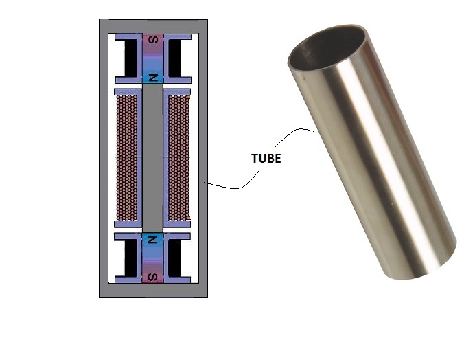 Exactly MM, nail it down!!Originally posted by marathonman View Post
NO DISRESPECT TO NO ONE BUT Sorry to spoil the lovely parade, the device above WILL NOT WORK.
Reason 1.
Primaries are way, way to small to even reach the middle of the secondary let a lone reach the opposite side. very little field strength will reach the end.
MM
But this FACT is stated in the 1908 Patent Drawing...however, Mr Bright Hanon...decided to change it to his own concept...
[IMG] [/IMG]
In Figuera actually that "RATIO" bolts down to 2X on Primaries to 1X on Secondaries...it was written since 1908...:
[IMG] [/IMG]
It is exactly like I wrote before...Hanon's Observation and Interpretations are down to Zero...
But Hanon will still argue with Us about him being right...
No wonder Hanon has not being able to show any working Figuera Device...in like how many years by now??!!
@MM, Glad you've got a good rest...batteries recharged...great!!
UfopoliticsLast edited by Ufopolitics; 01-06-2017, 03:34 PM.
Leave a comment:
-
Wrong Move
Hanon;Originally posted by hanon1492 View PostBistander,
You are right that your proposal to reduce the path thru air will create a much powerful field. But I think that if you use one configuration as the one shown in the image below (which represents your proposal) you will have the same air path whether you move the magnetic lines closer or further from each electromagnets in its movement. In that case the reluctance (which is the main resistance to the magnetic flow) will be the same independently of the distance along the induced coil and the field lines will not move at all IMHO. We have two magnetic forces fighting. In order to move the colliding plane back and forth they need some variable reluctance to overcome. If that reluctance is always the same I think we wont get any field movement, no matter the current modulation that you use.

In this case I only see a possibility if the permeability of the induced core is smaller than the perneability of the two electromagnets core, maybe nickel, ferrite or other metal with lower permeability than soft iron or magnetic steel (used as electromagnet cores)
Maybe Figuera was forced to used a huge reluctance (air path) and thus his electromagnets were weak and he needed 7 groups in series to have a pretty good output. From my test I can say that even with weak electromagnets with huge air path a good induction can be achieved with this method
Quote; "About MM statements he also manifested that with resistive wire and 100 watts input he got 300 watts in the induced coils. If you are interested I can look for the exact post and quote it again."
everyone is well aware of my post as you have repeatedly posted it numerous times. you still don't get it do you.????? with resistors it will never be self sustaining something you apparently can not grasp. Figuera's system is CLOSED LOOP SYSTEM.
NO DISRESPECT TO NO ONE BUT Sorry to spoil the lovely parade, the device above WILL NOT WORK.
Reason 1.
Primaries are way, way to small to even reach the middle of the secondary let a lone reach the opposite side. very little field strength will reach the end.
Reason 2.
the so called cylinder you plan on installing on the outside will magnetically ground themselves out.
electricity and magnetic fields always take the shortest or least path of resistance no mater how you roll the dice. so by you installing the cylinder on the out side you give the magnetic field from both electromagnets a SUPPER HIGHWAY HOME..... the quickest path to the South pole thus you will be loosing probably 3/4's of your magnetic field through that cylinder of magnetic death.
The whole reason Figuera used the open air design was restrict the change of currant between the primaries. see with the large air path it will have a higher degree of reluctance, resistance to change. so by restricting the change the field will be more easily controllable to currant fluctuations. that and the fact that two primaries add up to the secondary output..... remembering the output supply is split between them both.
the magnetic field will will still retain 80 to 90 % of it's intensity all while being moved from side to side with very little effort as the reluctance air path restricts the change so the primaries retain their magnetic field SEEING VERY LITTLE CHANGE.
Seaad;
While you may get some good results from your Ferrite core the amount of Ferrite you need for a reasonable output will be astronomical
compared to Iron or Lamination's. just saying, happy Figuering.
MMLast edited by marathonman; 01-06-2017, 03:15 PM.
Leave a comment:
-
E-core
Hi hanon,Originally posted by hanon1492 View PostBistander,
You are right that your proposal to reduce the path thru air will create a much powerful field. But I think that if you use one configuration as the one shown in the image below (which represents your proposal) you will have the same air path whether you move the magnetic lines closer or further from each electromagnets in its movement. In that case the reluctance (which is the main resistance to the magnetic flow) will be the same independently of the distance along the induced coil and the field lines will not move at all IMHO. We have two magnetic forces fighting. In order to move the colliding plane back and forth they need some variable reluctance to overcome. If that reluctance is always the same I think we wont get any field movement, no matter the current modulation that you use.

In this case I only see a possibility if the permeability of the induced core is smaller than the perneability of the two electromagnets core, maybe nickel, ferrite or other metal with lower permeability than soft iron or magnetic steel (used as electromagnet cores)
Maybe Figuera was forced to used a huge reluctance (air path) and thus his electromagnets were weak and he needed 7 groups in series to have a pretty good output. From my test I can say that even with weak electromagnets with huge air path a good induction can be achieved with this method
The tube you show is not what I had in mind with E-core. I'll try to get a diagram with better explanation. And I guess I don't understand your coments about variable reluctance. Typically that involves moving iron. Or saturation. Neither of which are evident in the work by CF.
Regards,
bi
Leave a comment:
-
Wrong Again...Hanon.
Hanon,Originally posted by hanon1492 View PostI think your interpretation of the result from your test is wrong. PSU show the output power in V and I which are delivering. Therefore if your test is increasing V and I in the PSU it is a sign that your device is cosuming more and more power, not the contrary as you are interpreting that power is send from the electromagnets to the PSU.
About MM statements he also manifested that with resistive wire and 100 watts input he got 300 watts in the induced coils. If you are interested I can look for the exact post and quote it again.
You tend to run your mouth without really "engaging" it properly with your brain...which in your case is very small...Which causes your huge IGNORANCE...and ignorance is daring, blunt, most of times like in your case.
First Of ALL, REGULATED PSU's have something called A REGULATOR CIRCUIT
ANY REGULATED Power Supply NO matter if Linear or Switched have something called "Voltage Regulator", which means that whenever you reach that V Value with its potentiometers it creates what is called a LIMIT...and that LIMIT works for either Volts or Amps...and so, it is not allowed to "self increase randomly"...just like that, unless the regulator at PSU is damaged or malfunctioning...otherwise it would not be called "REGULATED POWER SUPPLY".
Second: POSITIVE AND NEGATIVE FEEDBACK CONTROL
MOST REGULATED PSU's have NEGATIVE FEEDBACK CONTROL, But NOT ALL HAVE POSITIVE FEEDBACK CONTROL.
Negative Feedback Control is required to prevent "Droops" on the system being tested...search for droop failures.
It occurs when the load being tested demands MORE from the Power Supply can feed...as PSU tries to keep up with load being tested until the OVERLOAD PROTECTION CIRCUIT is then triggered...and PSU shuts down to prevent further damage to itself and to equipment being tested.
Must PSU's do not have a Positive Feedback Control...and this is VERY SIMPLE to be tested:
Install a Brushed Motor to a PSU, no matter if switched or linear, and while it is ON...BUT with ALL Dial Knobs at Zero...meaning, showing exactly ZERO Volts and ZERO Amps, MEANING ZERO OUTPUT...Then start turning your motor shaft...do it faster...and faster....and you will notice the either digital or analog meters start to raise up...if you turn your motor one direction Volts will increase...and if you turn motor the opposite spin then amps will increase.
THAT MEANS YOUR PSU HAVE ABSOLUTELY NO POSITIVE FEEDBACK CONTROL.
And like I wrote before, MOST PSU's do NOT have a Positive Feedback Control. Unless they are dedicated to power generation or power regeneration equipment.
One of the bigger problems you have...is your LACK OF EXPERIMENTING, which, of course, CONTRIBUTES to your complete LACK OF ANALYSIS, FEEDING YOUR IGNORANCE GALORE.
And then, on top of all the above...you dare to tell ME, I am wrong in my analysis...incredible!!
@Bistander or Citfta...Please guys, could you ILLUSTRATE Hanon about his wrong concepts?...appreciate it...that way He may believe what I have written above...many thanks in advance!!
UfopoliticsLast edited by Ufopolitics; 01-06-2017, 02:51 PM.
Leave a comment:
-
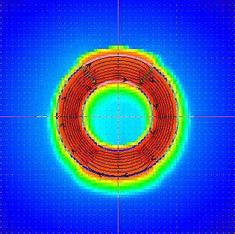
Toroid fields
Originally posted by Cadman View Post
Hi CM,
Notice similarity and difference between your simulation and iron powder pattern. One difference is the lack of iron powder inside the ring even though that is where the powder was dumped. But the simulation shows lines inside. Curious disagreement. I'll add the source vid for the iron pattern.
Regards,
bi
http://www.energeticforum.com/redire...%3D-2vAMmn2WzI
Leave a comment:
-
Good result; Figuera "Transformer" with open ends
I have got good results with a thin ferrite rod; Figuera "Transformer" with open ends but in the 5kHZ range. http://www.energeticforum.com/293596-post1326.html / ArneAttached Files
Leave a comment:
-
Bistander,Originally posted by bistander View PostHi CM,
I hear you. Not much of a magnetic circuit with so much path thru air and associated high reluctance. You might consider adding back iron. Thinking like an E core with center leg near middle coil and two end legs up against outside ends of primary cores. Use cross section area of E equal to that of coil cores. I think something like that could direct a lot of the dense flux (red area) thru the secondary wires.
Regards,
bi
You are right that your proposal to reduce the path thru air will create a much powerful field. But I think that if you use one configuration as the one shown in the image below (which represents your proposal) you will have the same air path whether you move the magnetic lines closer or further from each electromagnets in its movement. In that case the reluctance (which is the main resistance to the magnetic flow) will be the same independently of the distance along the induced coil and the field lines will not move at all IMHO. We have two magnetic forces fighting. In order to move the colliding plane back and forth they need some variable reluctance to overcome. If that reluctance is always the same I think we wont get any field movement, no matter the current modulation that you use.

In this case I only see a possibility if the permeability of the induced core is smaller than the perneability of the two electromagnets core, maybe nickel, ferrite or other metal with lower permeability than soft iron or magnetic steel (used as electromagnet cores)
Maybe Figuera was forced to used a huge reluctance (air path) and thus his electromagnets were weak and he needed 7 groups in series to have a pretty good output. From my test I can say that even with weak electromagnets with huge air path a good induction can be achieved with this methodLast edited by hanon1492; 01-06-2017, 12:35 AM.
Leave a comment:
-
Originally posted by Ufopolitics View Postthe Switching PSU kind of "automatically" starts rising up Voltage and Amperage....to a point of acceleration where huge sparks start appearing at commutator.
And it was very interesting as funny to see that the more I speed up the small motor...the higher PSU will display its V&A...
I think your interpretation of the result from your test is wrong. PSU show the output power in V and I which are delivering. Therefore if your test is increasing V and I in the PSU it is a sign that your device is cosuming more and more power, not the contrary as you are interpreting that power is send from the electromagnets to the PSU.Originally posted by Ufopolitics View Posta resistor set up would NEVER, EVER be able to self sustain.
About MM statements he also manifested that with resistive wire and 100 watts input he got 300 watts in the induced coils. If you are interested I can look for the exact post and quote it again.Last edited by hanon1492; 01-06-2017, 12:23 AM.
Leave a comment:
-
Well, glad to see Software is good for that analysis on Toroid with repulsive poles...as it should be "instructed" that toroids have almost no magnetic losses...so can not just "vaporize" that flux right?...;DOriginally posted by Cadman View PostThank you sir.
Thanks Ufo, I'm doing much better for now.
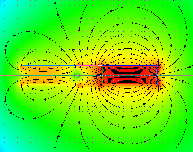
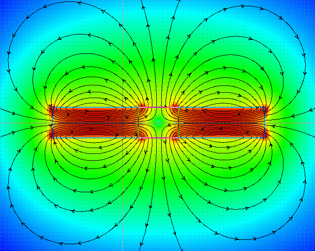
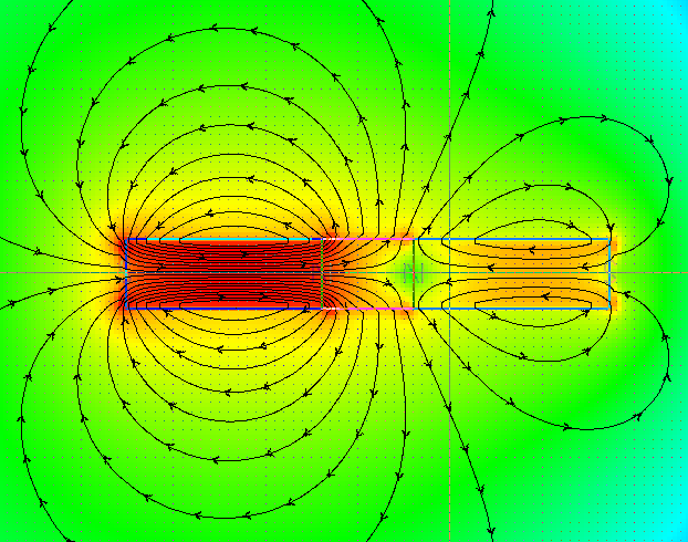
I do hope your theory is proven as you say. But software might not be useless for this, look at these. This what I AM building. It's a toroid cut into four pieces. Two coils, 248 turns, span 110 degrees each, two inducers at 70 degrees each.
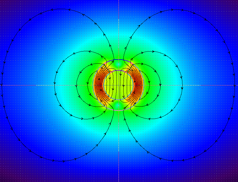
1 amp each coil.
But look at this, dropping the current 0.01 amps to 0.99 amp on the left coil.
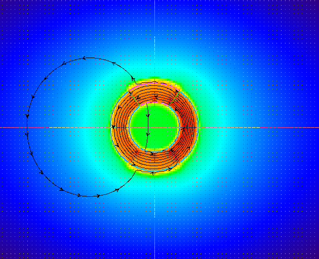
0.99 amp in left coil, 1 amp in right coil
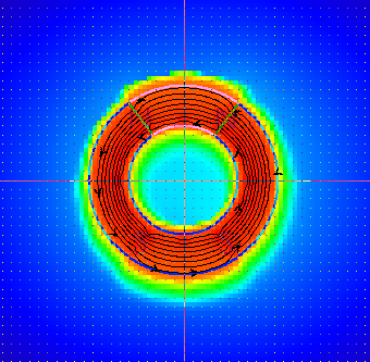
dropping to 0.5 amp in left coil
and this is reversed with 1 amp left, 0.5 amp right.
Notice the flux direction?
That's all for now.
Regards
Cadman
I am also working on something similar Cadman...as I have posted before...I call it Figuera TPU...
Regards and am very glad you are well now!
Ufopolitics
Leave a comment:
-
Thank you sir.Originally posted by bistanderVery nice CM. Well done.
Thanks Ufo, I'm doing much better for now.Originally posted by Ufopolitics View PostThanks Cadman,
Sorry to read you have got disappointed based on Software Results...
Problem I see is that there are absolutely No Software, No Scientific proven fact...which realizes that between those two North Poles is originated a High Pressurized Compressed Field (And I am calling "A Field" to this common pressurized area between Both Norths...Unfortunately Science has not recognized that fact yet...but that Flux Density ONLY exists between N-S Poles...and that is simply not true!...I guarantee I DO can prove that fact.
And related to My Real Set Up...I am having good induction no matter what software says...and not working with Part G yet...I got my Linear PSU running and ready to go....am just finding the best Primary-Secondary-Primary size ratios...
Then what are you gonna be building then?
Regards and wish you are much better, health wise.
Ufopolitics
I do hope your theory is proven as you say. But software might not be useless for this, look at these. This what I AM building. It's a toroid cut into four pieces. Two coils, 248 turns, span 110 degrees each, two inducers at 70 degrees each.

1 amp each coil.
But look at this, dropping the current 0.01 amps to 0.99 amp on the left coil.

0.99 amp in left coil, 1 amp in right coil

dropping to 0.5 amp in left coil

and this is reversed with 1 amp left, 0.5 amp right.
Notice the flux direction?
That's all for now.
Regards
Cadman
Leave a comment:
-
Linear PSU Testing...
Hello to All,
I am conducting some tests stills with resistors...
But now that I am using my Linear PSU...I can confirm, for sure now, that the Voltage raise as Amps rise when accelerating-decelerating power switch shown on previous video with switching PSU...is very real, No PSU failure at all...and without touching the PSU dial buttons.
Which concludes that Primaries Constantly keep sending back power to source...and it is not reversed/negative power, but very positive increase.
And so, resistors can NOT do anything with this extra power...but send it back to source, while loosing some in heat, not much in my set up though....
Honestly it is not about a heat issue with resistors, these 300W Power Resistors with Heat sink I have barely gets even warm...but an Exciter System which could Recycle Power is what am talking about here AND THAT is definitively NEVER going to take place with resistors.
Which confirms what MM wrote once before to Hanon...that a resistor set up would NEVER, EVER be able to self sustain.
Therefore I am gonna proceed with Part G building and testing...with linear PSU.
Regards
UfopoliticsLast edited by Ufopolitics; 01-05-2017, 06:45 PM.
Leave a comment:
-
Originally posted by Cadman View PostHi Ufo
It's a simulation I ran to test the idea of the induced core swapping polarities, which this confirms.
The software uses amp turns only. V=I*R and I=V/R you know.
Yes I am using part G in real life.
However you might be surprised to know this sim convinced me to NOT build this set up! The flux strength put through center core is rather pathetic due to excessive reluctance in the air path, and this is what I expected to see. Unless you or MM or someone shows otherwise I consider this set up to be a dead end.
Don't misunderstand, I am still continuing with my build.
Regards,
Cadman
Thanks Cadman,
Sorry to read you have got disappointed based on Software Results...
Problem I see is that there are absolutely No Software, No Scientific proven fact...which realizes that between those two North Poles is originated a High Pressurized Compressed Field (And I am calling "A Field" to this common pressurized area between Both Norths)...Unfortunately Science has not recognized that fact yet...but that Flux Density ONLY exists between N-S Poles...and that is simply not true!...I guarantee and I DO can prove that fact.
And related to My Real Set Up...I am having good induction no matter what software says...and not working with Part G yet...I got my Linear PSU running and ready to go....am just finding the best Primary-Secondary-Primary size ratios...
Then what are you gonna be building then?
Regards and wish you are much better, health wise.
UfopoliticsLast edited by Ufopolitics; 01-05-2017, 06:37 PM.
Leave a comment:
-
Hi CM,Originally posted by Cadman View PostHi Ufo
It's a simulation I ran to test the idea of the induced core swapping polarities, which this confirms.
The software uses amp turns only. V=I*R and I=V/R you know.
Yes I am using part G in real life.
However you might be surprised to know this sim convinced me to NOT build this set up! The flux strength put through center core is rather pathetic due to excessive reluctance in the air path, and this is what I expected to see. Unless you or MM or someone shows otherwise I consider this set up to be a dead end.
Don't misunderstand, I am still continuing with my build.
Regards,
Cadman
I hear you. Not much of a magnetic circuit with so much path thru air and associated high reluctance. You might consider adding back iron. Thinking like an E core with center leg near middle coil and two end legs up against outside ends of primary cores. Use cross section area of E equal to that of coil cores. I think something like that could direct a lot of the dense flux (red area) thru the secondary wires.
Regards,
bi
Leave a comment:
-
Leave a comment: