Hi Ufo
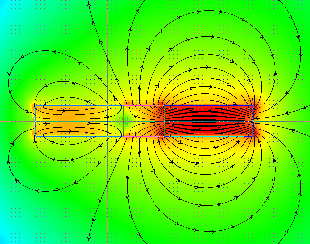
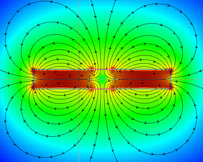
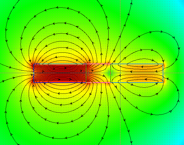
It's a simulation I ran to test the idea of the induced core swapping polarities, which this confirms.
The software uses amp turns only. V=I*R and I=V/R you know.
Yes I am using part G in real life.
However you might be surprised to know this sim convinced me to NOT build this set up! The flux strength put through center core is rather pathetic due to excessive reluctance in the air path, and this is what I expected to see. Unless you or MM or someone shows otherwise I consider this set up to be a dead end.
Don't misunderstand, I am still continuing with my build.
Regards,
Cadman
Announcement
Collapse
No announcement yet.
Re-Inventing The Wheel-Part1-Clemente_Figuera
Collapse
X
-
Originally posted by Cadman View Post
Hey Cadman!!
Fields look pretty well, sweeping length is perfect!!
Is that based on your real set up?...or just a simulation?
I am testing right now a very similar spec set, primaries are identical and secondary is just 1/2 inch longer...what voltage are you using with those amps?
And are U using Part G?
Could you please give some info?
Thanks Friend!!
UfopoliticsLast edited by Ufopolitics; 01-05-2017, 05:13 PM.
Leave a comment:
-
Leave a comment:
-
The magic of the Figuera generator is that makes possible to convert two variable magnetic fields in time in the electromagnets (dB/dt) into a variable magnetic field in space (in the induced coils), as happens in all generators ( emf = v • B ) moving back and forth the magnetic lines to create a relative velocity (v) between the lines and the wires, and, therefore creating induction by flux cutting the wires.

Leave a comment:
-
New Simplified Table
Agree...done deal!!Originally posted by bistanderChange "Rotary" to motion. There are linear generators (and motors).
[IMG] [/IMG]
I also changed the title...just a bit.
Regards
UfopoliticsLast edited by Ufopolitics; 01-04-2017, 08:04 PM.
Leave a comment:
-
Let's start opening Horizons...
Great Bistander!!Originally posted by bistander View PostUfo,
You put forth an argument but appear to agree. The motion generated voltage needs to be treated differently than the stationary induced emf. I agree both use a magnetic field and result in an emf.
Thought we tabled this.
bi
So, let's "Table" this for real...glad we reach an agreement!!
[IMG] [/IMG]
By the way...I should have called the Graph above not "Simplify" but "Generalize" the Induced EMF Process...
And of course, we could "complicate" the above graph...by adding Parameters Involved, Math Formulas, etc,etc..However, it will not change the Main View Order.
And please...if you do not agree with something on the above Graphic...even the colors...please let me know and I -for sure- will change it...
Regards
UfopoliticsLast edited by Ufopolitics; 01-04-2017, 04:06 PM.
Leave a comment:
-
Fields
Ufo,
You put forth an argument but appear to agree. The motion generated voltage needs to be treated differently than the stationary induced emf. I agree both use a magnetic field and result in an emf.
Thought we tabled this.
bi
Leave a comment:
-
Originally posted by bistander View PostG'morning Ufo,
If they are the same thing, why then is maximun induced voltage seen with primary field-secondary field alignment in a transformer and maximun generated voltage seen when main field-armature field is in quadrature in the generator?
Motion is the difference.
bi
Good Morning Bistander,
Well, like I wrote before in my last statement on my last post...:
Meaning FIELD CHANGES are simply originated by different Factors in your both cited examples above...and so, they Generate differently the resulting EMF.Originally posted by Ufopolitics View Post
BOTH EFFECTS ARE IDENTICAL, SAME NATURE...SAME ORIGINS...JUST DIFFERENT MANIFESTATIONS THROUGH DIFFERENT PARAMETERS.
AND SO, OF COURSE, SINCE DIFFERENT PARAMETERS ARE INVOLVED, THEN DIFFERENT MATHEMATICAL EQUATIONS MUST BE APPLIED...TO CALCULATE THE SAME EXACT EFFECT...A FIELD CHANGE TO OBTAIN AN EMF...SIMPLE.
Of course...and "Motion" means a Variation through Space/Time...which are different Parameters as the ones involved in Transformers.Originally posted by bistander View PostMotion is the difference.
However, this is an "apparent" difference...since in Transformers, the Time Parameter is dictated by a fixed frequency from the AC sine E.G: Sixty (60) cycles per second.
While in a Generator, the "right motion" is only achieved when rotor reaches a specific speed...3600 RPM's which derives in exactly same given example as above...60 Cycles per second.
What we are changing are the Parameters to obtain the same thing...the Field Change, which in turns generates the EMF...and so, different parameters to Change Field will result in different forms of EMF manifestations.
When I was carefully observing the waves obtained by my Figuera Set up on my Scope...I realized that the Signal obtained at output is just a "Mixed Result" from both simultaneously signals generated by both Primaries Inductors...and so, this output signal is completely different from the one generated by either an AC Transformer or an Electric Generator....that we could "smooth" it out and make it "appear" just like both devices mentioned?...of course we could...You and I know very well we could "modify" signal and make them all look the same way.
Let me try to put it in a more simple way...
The Field Changes or Field Variations (no matter the source is producing it) establish a Pattern, which Pattern in turn is "reproduced" on the Induced or Secondaries just like an "Echo"...or a Magnetic Resonance, which produces an EMF we can work with directly...meaning it is the "tangible" result...from an "Intangible Pattern" which is derived from the varying-changing magnetic field...
Hope it is better explained now...
Regards
UfopoliticsLast edited by Ufopolitics; 01-04-2017, 05:39 PM.
Leave a comment:
-
Fields
G'morning Ufo,
If they are the same thing, why then is maximun induced voltage seen with primary field-secondary field alignment in a transformer and maximun generated voltage seen when main field-armature field is in quadrature in the generator?
Motion is the difference.
bi
Leave a comment:
-
The Same, Exact Thing...different "Colors"...
Do not agree with the above AT ALL!!...:Originally posted by hanon1492 View PostFeynman speaking about two different phenomena in induction. Pay attention to the linked video.
One is manifested in transformers (flux changes: emf = A•dB/dt ) and other is manifested in generators (circuit moves: emf = v•B )
Feynman about two different phenomena in induction on Vimeo
NOT TWO DIFFERENT "PHENOMENA"...BUT JUST THE SAME, EXACT EFFECT!!
There are absolutely NOT TWO different phenomena there at all...BUT JUST ONE!!...BOTH, bolts down to the same, identical effect.
In BOTH there is a CONSTANT, COMMON FACTOR which is simply DEFINED AS: FIELD CHANGES, as stated in Faraday First Law to obtain an Induced EMF.
And so, WHATEVER MEANS we use to generate A FIELD CHANGE will produce an EMF.
We can generate FIELD CHANGES by variations from its source, like a Transformer which works only on AC Source, since AC is ALWAYS CHANGING.
OR, Like Figuera...Who discovered a NEW way to CHANGE FIELD by developing a NEW CHANGING SOURCE derived from a DC SUPPLY...
We can generate FIELD CHANGES by variations through SPACE/TIME like Generator does.
And there should be MANY OTHER WAYS to achieve a CHANGING FIELD...which We still have no idea could be possible...just because We have not discover them yet..
And by FRAGMENTING this SINGLE PHENOMENA into TWO...AS considering BOTH ARE DIFFERENT...ALL We are doing is LIMITING OURSELVES for ACCEPTING other new forms which could be discovered.
Your "view" above is just a CONSEQUENCE from the first statement you posted, and obviously agree with..."Two Different Things"...when BOTH are EXACTLY THE SAME DEAL...WITH DIFFERENT "COLORS".Originally posted by hanon1492 View PostAnd now my view: In transformers Lenz is manifested as an opposed field to the inducer field. In generators Lenz is manifested, not as an opposed field to the inducer electromagnets, but as a dragging in the moving armature which has to be overcomed with more mechanical energy. If nothing moves...
Then You write:Originally posted by hanon1492 View PostIn transformers Lenz is manifested as an opposed field to the inducer field.
In Transforner "nothing moves"...In Figuera "nothing moves"...then what makes you think that in Figuera, Lenz would not be manifested as it does in Transformers??!!Originally posted by hanon1492 View PostIf nothing moves...
Then You write:
Your above statement is completely DEAD WRONG!!Originally posted by hanon1492 View PostIn generators Lenz is manifested, not as an opposed field to the inducer electromagnets, but as a dragging in the moving armature...
In Generator Lenz IS manifested EXACTLY as TWO OPPOSED FIELDS, which CAUSES/RESULTS AS A Magnetic-Mechanical DRAG...
1- When Field Rotor (Inducer) IS MOVING AWAY from Induced Field, Lenz creates an OPPOSED MAGNETIC ATTRACTION, which opposes to the Rotor Movement.
2- When Field Rotor (Inducer) is APPROACHING to Induced Field , Lenz generates a MAGNETIC REPULSION FIELD, which OPPOSES to Rotor approaching movement.
In Generators, Lenz becomes TWO OPPOSED FIELDS/FORCES which Oppose to Rotor Mechanical Spin...
This is SO SIMPLE...BUT You COMPLICATE IT so much, just because of your completely OFF, then WRONG Conclusions...
BUT DO NOT FEEL BAD...THIS IS THE WAY IT HAS BEEN DONE FOR MORE THAN A CENTURY...
BOTH EFFECTS ARE IDENTICAL, SAME NATURE...SAME ORIGINS...JUST DIFFERENT MANIFESTATIONS THROUGH DIFFERENT PARAMETERS.
AND SO, OF COURSE, SINCE DIFFERENT PARAMETERS ARE INVOLVED, THEN DIFFERENT MATHEMATICAL EQUATIONS MUST BE APPLIED...TO CALCULATE THE SAME EXACT EFFECT...A FIELD CHANGE TO OBTAIN AN EMF...SIMPLE.
UfopoliticsLast edited by Ufopolitics; 01-04-2017, 06:22 PM.
Leave a comment:
-
Feynman speaking about two different phenomena in induction. Pay attention to the linked video.
One is manifested in transformers (flux changes: emf = A•dB/dt ) and other is manifested in generators (circuit moves: emf = v•B )
Feynman about two different phenomena in induction on Vimeo
From Richard Feyman, Nobel Prize Winner 1965, in his lectures Vol.2 Chapter 17:

"So the “flux rule”—that the emf in a circuit is equal to the rate of change of the magnetic flux through the circuit—applies whether the flux changes because the field changes or because the circuit moves (or both). The two possibilities—“circuit moves” or “field changes”—are not distinguished in the statement of the rule. Yet in our explanation of the rule we have used two completely distinct laws for the two cases—v×B for “circuit moves” and ∇×E=−∂B/∂t for “field changes.”
We know of no other place in physics where such a simple and accurate general principle requires for its real understanding an analysis in terms of two different phenomena. Usually such a beautiful generalization is found to stem from a single deep underlying principle. Nevertheless, in this case there does not appear to be any such profound implication. We have to understand the “rule” as the combined effects of two quite separate phenomena."
And now my view: In transformers Lenz is manifested as an opposed field to the inducer field. In generators Lenz is manifested, not as an opposed field to the inducer electromagnets, but as a dragging in the moving armature which has to be overcomed with more mechanical energy. If nothing moves...Last edited by hanon1492; 01-10-2017, 10:59 AM.
Leave a comment:
-
Matu,Originally posted by Matu View PostHola:
Perdona Ufo, es cierto, quizás me he precipitado pero he creído que esto podía confirmar tus experiencias, de todas formas comprobaré también con fuente externa, no obstante por si quieres comprobarlo, alimentando con baterías y teniendo todo en marcha sin carga en la inducida, mis baterías aumentan su voltaje, aunque no tengo colocados diodos.
Con baterias no me ha funcionado, sencillamente porque en un sistema de baja resistencia como este, las baterías arrojan todo su amperaje y esto no es bueno.
A eso precisamente me refiero...ese amperaje es demasiado alto debido a la baja resistencia ...y lo que pasa es que los núcleos de hierro se sobre saturan y entonces el campo magnético de repulsión deja de hacer su función inductora.Originally posted by Matu View PostMI parte G está hecha con hilo nicrom (barbacoa...
 ) 25 ohm y primarias de 2,3 ohm, pero también tengo otro con toroide de fleje de hierro de 45 vueltas de hilo de 1,2 milimetros, aunque en este caso el consumo se dispara hasta los 13 Amp.
Gracias por tu gran aportación al generador Figuera.
Saludos
Tienes que regular el amperaje a mucho menos, como 6 o 7 amperes máximo...y eso solo lo consigues con una fuente reguladora LINEAL, no Pulsada...ésta última no funciona...como la que muestro en el video arriba sólo funciona bien con resistores sin parte G...
Saludos
UfopoliticsLast edited by Ufopolitics; 01-03-2017, 08:29 PM.
Leave a comment:
-
Resistors and Diodes Test Video...
Hello to All,
And like I have promised before the short video on the testing...
[VIDEO]https://www.youtube.com/watch?v=P51Pi-VTlfA&feature=youtu.be[/VIDEO]
RESISTORS TEST WITH DIODES
And we have to understand the current flow is going at two different and opposite roads as passing through different resistance values, so it is understood amperage would fluctuate as well, I mean, that´s the point here.
What I find interesting is that at Low speeds amperage climbs up...as it does at very high speeds as well...as I show close to video's end...and like I said on video, it may be a failure from PSU, on its read out screen by being fooled by so fast changing currents directions plus stepping through different resistors values...PSU Signal Processor can not keep up with signals...but honestly can not tell for sure what´s going on here but speculation.
As when I put an Incandescent Bulb at output, Input nor motor speed change not even a bit...which is absolutely great...
I am definitively going to finish building another set or maybe two more, then connecting in series to this one...primaries and secondaries...and testing again...
Regards
UfopoliticsLast edited by Ufopolitics; 01-03-2017, 09:57 PM.
Leave a comment:
-
Traductor...
Hola:
Perdona Ufo, es cierto, quizás me he precipitado pero he creído que esto podía confirmar tus experiencias, de todas formas comprobaré también con fuente externa, no obstante por si quieres comprobarlo, alimentando con baterías y teniendo todo en marcha sin carga en la inducida, mis baterías aumentan su voltaje, aunque no tengo colocados diodos.
MI parte G está hecha con hilo nicrom (barbacoa...
 ) 25 ohm y primarias de 2,3 ohm, pero también tengo otro con toroide de fleje de hierro de 45 vueltas de hilo de 1,2 milimetros, aunque en este caso el consumo se dispara hasta los 13 Amp.
Gracias por tu gran aportación al generador Figuera.
SaludosLast edited by Matu; 01-03-2017, 07:45 PM.
Leave a comment:
-
Hola Matu, enhorabuena!!Originally posted by Matu View PostHola a todos:
Antes que nada quiero pedir perdón por escribir en español, no hablo ingles...
@All: Matu is saying hello as excusing himself for writing here in Spanish as He does not speak English...
Originally posted by Matu View Post@Ufo: Acabo de comprobar, que mis baterías cogen carga dejándolas un rato ( como 5 minutos), lo cual creo puede confirmar lo que vd. dice, sin embargo al cargar la secundaria se nos esfuma la magia... ensando: seguramente el exceso de energía en las primarias no es suficiente para compensar la carga, solo tengo conectado un conjunto.(espero haber entendido su mensaje con el traductor "San Google")... :RE:RE
Seguiremos investigando, un saludo desde Castilla la Mancha (la tierra de D. Quijote)... :abrazo:
Saludos
Castilla, la Mancha...la tierra del Quijote!!...bella tierra!!
Pero Matu, Yo estaba hablando del experimento de Figuera, sin baterias... estoy alimentandolo con una fuente externa (PSU en inglés Power Source Unit)
Lo que manifiestas es lo que llamamos una carga ¨superficial en baterias cuando se dejan en reposo...pero las lecturas son falsas...no duran lo suficiente.
En Figuera estoy experimentando un aumento de energía proveniente de los electroimanes excitadores (Inductores ó Primarios), cuando acelero el pequeño motor.
Abrazos
Ufopolitics
Leave a comment:


Leave a comment: