Hi guys,
@ Bitstander:-
I think what I do not get at the armature connection is an expected the dual output from a single input. I get the rotational magnetic field, and the impressed sinewave output.
@ Hi guys,
I think the conversation has developed into a fundamental dissection of basic principles. I am mindful of Tesla's comment that the Canary Islands should give a good environment for Clemente's device. Also, some time back I had a discussion on the energeticscienceforum about the Figuera generator. This discussion was centred on the collection of radiant/ambient energy using external collector shields. I did not quite understand the process at the time, but, since doing some work on Don Smith, I get the relevance. That is, the external field/space surrounding the device in question is the source of the energy:- the collectors operate in this zone. Therefore, I might conclude that, developing a regular sinewave output is the problem. It is the context of differential energies that seems to be where the issue of energy magnification might be resolved. That is, disturbing the background or surrounding space. Maybe, radient spikes are required?
I still do not quite get the motional electric fields yet. Perhaps, it is the way Hooper uses terms that have a different connotation to the way I might use them!
Regards
Dwane
-
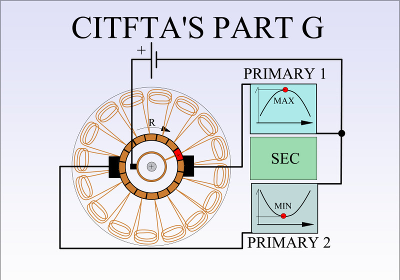
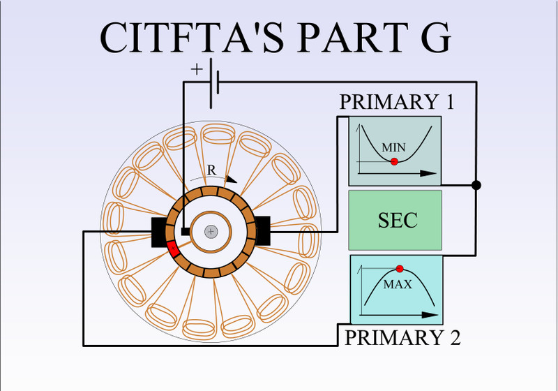
Some general aspects on Figuera and Part G.
Part G is just a remote controller to obtain Two Signals Opposed ALTERNATIVELY PLUS at UNISON, at 180� apart.
But the way Patent shows all independently set two primaries and just one secondary in the middle and all set apart from the others...does NOT work.
For the same Input to Two Primaries We could Induce Two Secondaries, but only LOOPED ALL FOUR within a TOROID CORE....then we have ONE MODULE.
I still have to test that set up with TOROID CORE...
Regards
UfopoliticsLeave a comment:
-
Well yes, I see your point, plus reason to be skeptic...and so am I.Originally posted by dragon View Post
I have been able to achieve a "hypothetical" OU with my set up...meaning if we read INDEPENDENTLY out Volts versus In Volts I get 50V IN versus 175V OUT...NOT LOADED.
And measuring (by shorting output with ampmeter) I get like 7-8 AMPS OUT using 2.0A at INPUT...no increase at INPUT.
Sounds wonderful right?
Well the issue is when LOADED Output (INCANDESCENT-HALOGEN BULB) Voltage DROPS way down too much...so like You wrote above: have to increase Input plus RPM at controller to satisfy load demand...but no longer OU.
I believe the issue I have is due to not having a closed core like a Toroid...I had OPEN CYLINDRICAL CORES on above test...so, I believe every cycle FIELD MUST RESTART from ZERO when output shorted by load...hence the V drop at load.
Interesting thing here is...that AMPERAGE remains the same at OU related to IN AMPS...versus OUT AMPS...with a FULL SHORT CIRCUIT from ampmeter.
All rotary generators have their field coils(INDUCED) enclosed within a Closed Core...so Field is not wasted in Space but remains within core...SO gets to a point where EXCITER is just moving EXISTING FIELD within core.
Regards
UfopoliticsLast edited by Ufopolitics; 09-07-2018, 05:17 PM.Leave a comment:
-
Excellent explanation... no offense intended simply my normal skepticism, unfortunately, it really doesn't help to explain the "extra" energy. Adding more secondaries simply requires more energy from the primaries to drive them so we are still at a loss in transformation ... how does one reduce the losses to achieve a unity ( or above ) outcome. Each one should exceed input thus adding to the total excess in output.Originally posted by Ufopolitics View Post
If we look at the diagram below, a generator patent from the late 1800's - series wound DC generator. In this case the armature coils would rotate inside the field coils. Current would begin upon rotation with either residual magnetism or another external initial excitation.
If we lock the armature in place and manipulate the field coils ( part G ) then we basically have a stationary generator. Now we have to create a force from the field coils equal to that of the force needed to rotate the armature through the original field. What we now have is a transformer. The field coils would operate with the lower voltage ( after the load ) with the current available dictated by the load. Using only the current available and the lower voltage provided after the load we need to transform the low voltage through the field coils to a higher voltage at the same amperage in the armature coils. How is that possible? As soon as we alter the voltage through the system the losses start showing up.
For instance if we have 100 watt bulb as a load and we're producing 120 volts at the armature but reducing the flow through the load to say 100 volts with 20 volts flowing through field coils we experience a major loss. We have .8 amps flowing through the circuit the bulb is absorbing 100 volts or 80 watts leaving us with 20 watts to manipulate the field coils. We need to take the 20 watts and manipulate it back into 120 watts to keep the cycle going....
There in lies my skepticism ....Last edited by dragon; 09-07-2018, 03:58 PM.Leave a comment:
-
Originally posted by dragon View Post
If We are gonna see each Module isolated (independently) from the rest (or just electrically connected in between through mere wires)...then of course...we must accomplish OU in just one.
But that's not the way it works...I mean common sense tells Us that "chaining" modules in a loop will result in 2 primaries for every 2 secondaries...
But MAIN adding in order to increase magnetic force/hence Output, would be when all independent modular magnetic fields ADD UP SPATIALLY because of the geometrical positioning in our design.
I have shown that before here...
UfopoliticsLast edited by Ufopolitics; 09-07-2018, 02:53 PM.Leave a comment:
-
If one "module" doesn't provide the outcome needed then adding more won't help. The extraordinary claims of 100 watts in to 20kw out would lead one to believe each "module" would/should deliver a 200:1 outcome...with 10 units each using 10 watts in giving 2000 watts out. Adding more modules increases the overall outcome. So, if your not achieving the results with one then your probably not going to achieve it with 2, 10, 50, or 100 modules.
There is always going to be conversion/transformation losses from one energy to another. What mechanism would allow even 100% transfer (unity) let alone a 200:1 transformation? The extra energy, if any, must come from somewhere....Leave a comment:
-
Sorry citfta I made a minor fault. I made my predictions from a G-part similar to the pic added. With yours G-module it is somewhat below 60-70.Originally posted by citfta View Post
Should be interesting to see MM:s latest G.part (When finished) with both + and - sweeping around.
https://overunity.com/12794/re-inven...4515/#lastPost
Regards ArneLeave a comment:
-
Hello Citfta,Originally posted by citfta View Post
Could you please share what your INPUT to Primaries Specs (Volts+Amps) are?
In general to ALL: Remember CF Generator is based on MULTIPLE MODULES of Primaries-Secondaries...so, do not expect to make it successfully w/ just one module.
Regards
UfopoliticsLast edited by Ufopolitics; 09-07-2018, 12:54 PM.Leave a comment:
-
Originally posted by seaad View Post
Hi seaad,
I am not even getting close to 50% out with the secondary and primary configurations I have tried. My part G is working fine at producing the opposing sine waves but the conversion between primary and secondary is very low. I have tried a couple of different coil arrangements and opposing as well as aiding magnetic fields. Have you found a way to get above the 60 - 70% you predicted?
CarrollLeave a comment:
-
The above Will work.
Maximum total efficiency between 60 - 70% (anyhow < 100%) in/out. (My prediction)
Please prove me wrong and tell me/us how the/any OU occurs.
Regards ArneLeave a comment:
-
Something on my mind!
Hi guys.
Dangerous territory. I have been thinking again!
1) Washing machine motor, with a single positive connection to the continuous winding of the armature, how does the alternate brush discriminate its 180degree phase with other brush?
2) Clemente's design is wasteful. Why have we not looked at primary oils wound on U shapes and then have two primaries cojoined with two secondary coils? Theoretical output times two?
3) have started reading William Hooper treatise on Motional electric fields. Not an easy grasp at first read! How would this fit in with Clemente's ideas?
Washing Machine motor hasn't arrived yet.
Regards
DwaneLeave a comment:
-
Hi Guys,
Are you sure this is fake? Is there not some sympathy with the devices we are talking about now? I must admit I have looked at some others last night. I particularly like this one, of which I posted a comment.
https://www.youtube.com/watch?v=I2i6vywEcNY.
This one really sucked in the "unclean"!
What is really good are the props and method. Casual work ethic, tired looking soldering iron and well used dirty glue gun. Brilliant!! This guy is a genius! He would have showed Hubbard a thing or two.
Thanks for the heads up on the field coils, doubt if I will see any of those lying about for some time. Still I can start looking.
Edit: youtube pays for videos? Where have I been all these years?
Regards
DwaneLeave a comment:
-
Yes, excellent video right!!??Originally posted by Dwane View Post
Oh!!..and we should also pay special attention to the type of wood utilized on such accurately built machine!!
IMHO the wood should have some kind of "specific" strength plus compactness which transmits properly all the frequencies involved...
Regards
UfopoliticsLast edited by Ufopolitics; 09-06-2018, 12:27 PM.Leave a comment:
-
Fake!!!
Dwane,
The video is a fake! UFO and I were just having fun making silly comments about it. Nothing as sloppily put together as that could possibly work like the video seems to claim.
To answer your questions though it appears the stator is from a multispeed induction motor similar to what is used in washing machines and dish washers. The armature looks similar to a universal motor such as used in power saws or vacuum cleaners.
Please don't waste any more time thinking about the video. It is like thousands of others that are posted to fool people that have no experience in electronics. The only purpose of the video is to try and get subscribers for his Youtube channel. The more subscribers he gets, the more money he gets from Youtube.
CarrollLeave a comment:

Leave a comment: