Announcement

Collapse
No announcement yet.

Re-Inventing The Wheel-Part1-Clemente_Figuera

Collapse
X
 
  • Filter
  • Time
  • Show
Clear All
new posts

  • cores

    MM,

    Thanks for the helpful info.

    So I guess your large square 1.5x1.5x3" cores is what gets you that large 25 ohm reactance. Mine are only at 6 ohms reactance. So got a long ways to go to make improvement.
    Hope you get the new unit working in the near future.

    Comment


    • Electromagnet force

      Originally posted by hanon1492 View Post
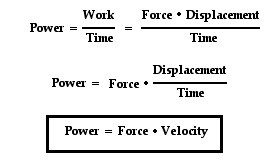
      The way to calculate it is with the equation: Power = Force • Velocity

      Taking as velocity the movement of the magnetic lines back and forth cutting the induced coil wires. Yo can go into further detail in this old post link. I recalculated that value of 14.8 lb/KW and I think it is adjusted for an induced coil length of 2 inches and a frequency of 60 Hz. If you are good with english units please confirm if I did it well or not. Thanks
      Hi hanon,

      Force does not relate power directly like you state. But I did find an article reducing certain properties to a generalized force statement as follows:

      The maximum force per unit area (which is pressure) which an iron core electromagnet can exert is approximately 145 lbf/in². See the physics section here: https://en.m.wikipedia.org/wiki/Electromagnet

      You had given a brief discussion on electromagnet force in post #1232 and included this from one of the references:


      Again you can see that the expression does not contain power or terms which could lead directly to a power or energy calculation. To do that, certain constraints must be defined.

      Originally posted by marathonman
      That 14.8 lbs force was given to me by meentor's figures but have lost contact to get all of equations. it had to do with horse power to watt conversion as explained to me. other conversions are necessary but i do not have them. all i have right now is the final outcome...... 14.8 lbs force per kilowatt. he was very specific about this.
      Perhaps MM could check with his source. Maybe I'm missing something and sure would like to know if that is the case.

      Regards,

      bi

      Comment


      • Originally posted by bistander View Post

        Again you can see that the expression does not contain power or terms which could lead directly to a power or energy calculation. To do that, certain constraints must be defined.
        Power = Force • Velocity is a basic physics equation for systems moving at certain speed overcoming a force against their movements, for example a car overcoming the force of the wind, or a generator rotating and overcoming the dragging force.. I think you have not clicked in the link I posted. There you find this image and quoted text:


        To compute the power you need to know the force and the velocity of the magnetic lines moving along the induced coil back and forth. So for example for 60 Hz inducer frequency and a induced coil length of L inches and supposing that the magnetic lines move along the whole coil length one way and the way back in every cycle, then each second you have a movement of 2•L•60 inches/sec. Therefore that force is related to power for certain frequency and for certain induced coil length.
        My calcs were for 2.5 inches length in the induced coil and frequency = 60 Hz.
        14.8 lb = 65.7 Newtons.
        2.5 inches =0.0635 meters

        P = Force • Velocity = Force • 2 • Length • Frecuency = 65.7*2*0.0635*60 = 500 watts.
        As this is just for one electromagnet, then the power of two electromagnets is 1000 watts. I am not sure if I must compute exactly (x2) or maybe lower because when one electromagnet is at maximum the other is not at the same strength. This is my doubt.


        Elcheapo, if one set of your electromagnets has an impedance of 6 ohms then at minimun impedance of the resistors or part G (0 ohms) your amperage for 50 volts will be 50/6 = 8.3 A. This will be your maximum current. Later you may add the amount of resistance wire you need to get to 50 ohms total and there you will have a minimun current of 1A, or any other value. I have the same concern as you have with a high intensity in that design. You always may reduce the input voltage but then you are not working with the same design as MM. There is something I do not understand...
        Last edited by hanon1492; 10-17-2016, 11:44 AM.
        https://figueragenerator.wordpress.com/

        Comment


        • Electromagnet force

          Hi hanon,

          Yes I follow your logic but it is flawed or invalid. I regret I lack the skills or knowledge to teach you. But please, show me one reputable scientist or engineer or academic using that power, force equation for an electromagnet. I believe the error comes from treating the magnetic field as an object.

          Regards,

          bi

          Comment


          • Originally posted by marathonman
            HANON;

            When i was conversing with your truly, he stated each electromagnet is accountable for half of the secondary output. the declining electromagnet should only be taken down just enough to clear the secondary while still retaining 80 to 90 % of it's strength. the flux traveling through air all the way back slows flux change allowing it to retain almost all of it's original flux field.

            hard to grasp at first i know.


            MM
            Good Morning MM, good morn to All,

            While I find your Mentor's first statement very clear and understandable...about each primary being responsible for half of secondary output...I really find it very hard to "grasp" that the retracting primary electromagnet is still retaining 80 to 90% of its strength.

            I am still conducting tests with just one primary...and when it is retracting I can easily pull the secondary core away from it...while when it is at max force...there is absolutely no way I can pull it at all!

            I really love the way Figuera "sees" and writes his observation on this part...As he considers that whenever an electromagnet is able to FULLY MAGNETIZE the INDUCED CORE, (which means when magnetic field has completely taken over the secondary core) is when Positive and FULL Induction takes place, as the opposite occurs when it retracts Field the effect reverses as so the induced EMF.

            So, I would understood as the retracting field should "give enough room" for the now expanding and stronger opposite field to take place over the same secondary iron core...and this way, the Total Induction output would really be split in half by both primaries.


            Anyways this is the way I see this effect without much complications.


            Regards


            Ufopolitics
            Principles for the Development of a Complete Mind: Study the science of art. Study the art of science. Develop your senses- especially learn how to see. Realize that everything connects to everything else.― Leonardo da Vinci

            Comment


            • Comm timing settings...

              Hello to All,

              As I am working now on the timing at commutator...I found out that by expanding the On timing at the Max Values, which is also the Min Value for the retracting one...and so by expanding this time the Full Max Induction reaches full peak at faster speeds...and so the retracting time descends a bit more as well. Therefore, I am achieving full displacement (penetration-retraction) of both fields now.

              As an example I am using a 20 segment comm, so I am allowing three segments for each Max-Min at 180º apart...and so, I have seven(7) above and seven(7) below contacts for the fluctuations in between.

              I am measuring the deflection angles with a horizontal line B&W CRT...and the problem is that by increasing the speed the angles get shorter, which means spatial deflections shortens...so we need to consider this fact to play with Max-Min ON time.

              There are many ways to solve this...as to replace comm by a bigger one with longer segments...but for now I rather keep playing with what I have without major complications.

              Just wanted to share this for those working with mechanical switching.


              Regards


              Ufopolitics
              Principles for the Development of a Complete Mind: Study the science of art. Study the art of science. Develop your senses- especially learn how to see. Realize that everything connects to everything else.― Leonardo da Vinci

              Comment


              • Originally posted by marathonman
                the declining electromagnet should only be taken down just enough to clear the secondary while still retaining 80 to 90 % of it's strength.
                Ideally it should be as you say. A small imbalance just move the two fields back and forth while almost retaining always the same magnetic pressure between both fields

                the flux traveling through air all the way back slows flux change allowing it to retain almost all of it's original flux field.
                I do not understand that statement
                https://figueragenerator.wordpress.com/

                Comment


                • Originally posted by marathonman
                  It could be he was actually referring to the E field, i'm not sure, i'll refer to my notes.
                  i have read that E fields remain for a time after stopping and that motors started after being shut off for less than three minutes start witth less currantt draw then from a cold start. this is an indication of reminant E field. so this also tells me E fields don't fluctuate like B fields do reacting much slower in closing that portal.

                  QUOTE;

                  "So, I would understood as the retracting field should "give enough room" for the now expanding and stronger opposite field to take place over the same secondary iron core...and this way, the Total Induction output would really be split in half by both primaries."

                  this is where the declining kick forward into part G takes place as the decreasing electromagnet gets shoved out of the secondary core confined in it's own core. whers is all that pressure to go??? to part G my friend.


                  something to think about.


                  MM

                  MM,

                  I know the way you picture this with part G...as it "absorbs" the retracting field from the declining e-magnet...

                  When we visualize a full Single Magnetic Field (like the primaries e-magnet) at Max values, and then when its currents are decreased to min values...we observe that the WHOLE Field kind of "shrinks" and that includes both poles and this process is "very symmetrical".

                  And this is an issue I am also observing here...as I keep getting Negative Spikes during this process which keep increasing at higher speeds.

                  Could it be that the retracting field is self inducing too much negatively on the coil?...which means when it is declining?

                  Speaking in a more technical and "classic" way...we could say that the retracting lines of force are cutting the wires in the opposite fashion, generating a negative kick, even if we are not allowing field to collapse?...

                  And here I better understand your point about the G Core "absorbing" all this reverse kick backs...

                  Do you think those negative spikes could be detrimental to the induction at secondaries or is it just a Primary issue which "stays there"...without affecting Induced EMF?


                  Thanks and regards


                  Ufopolitics


                  Edit: I added a Diode, blocking negative current flow...but it did absolutely nothing...and it is a very powerful and fast diode
                  Last edited by Ufopolitics; 10-17-2016, 02:33 PM.
                  Principles for the Development of a Complete Mind: Study the science of art. Study the art of science. Develop your senses- especially learn how to see. Realize that everything connects to everything else.― Leonardo da Vinci

                  Comment


                  • Originally posted by marathonman
                    UFOP;

                    My mentor and i talked about that very subject. what was discussed was the poles don't actually reverse but the wires don't know that. all they see is a receding field so to them it is collapsing so the spike could be that vertual receding field.
                    but i would like to know how many winds do you have as to many winds would have an adverse reaction to coil reaction and self induction.

                    that is why i have been harping at less winding's.

                    please give specs of coil and peak of spike. ie volts/amps


                    MM
                    MM,

                    As I am working right now on a single primary...and just have the fiberglass spool caps hold with glue and tape...I did not make such a detailed winding...so do not have exact # of turns or layers. What I know exactly is that it is 23 awg, and the length is 690 ft...which is exact as your table guide...gives me 14.6 ohms.

                    The Core is 4 inches long and 1 1/4 thick.

                    I am feeding with 36V 2.2 Amps Lipo batteries, and negative spikes go above the total batt value...like I have V Max at 34 V at Max and getting somewhere around 19V Negative spikes.

                    Amps reduce fine from 2 something to one something...50%


                    Many thanks


                    Ufopolitics

                    EDIT 1 I have been thinking as to make it 23 awg Bifilar...it will reduce ohms in half approx...but will have a double stronger field...
                    Last edited by Ufopolitics; 10-17-2016, 03:05 PM.
                    Principles for the Development of a Complete Mind: Study the science of art. Study the art of science. Develop your senses- especially learn how to see. Realize that everything connects to everything else.― Leonardo da Vinci

                    Comment


                    • [QUOTE=hanon1492;


                      Elcheapo, if one set of your electromagnets has an impedance of 6 ohms then at minimun impedance of the resistors or part G (0 ohms) your amperage for 50 volts will be 50/6 = 8.3 A. This will be your maximum current. Later you may add the amount of resistance wire you need to get to 50 ohms total and there you will have a minimun current of 1A, or any other value. I have the same concern as you have with a high intensity in that design. You always may reduce the input voltage but then you are not working with the same design as MM. There is something I do not understand...[/QUOTE]

                      No, I'm not using resistors for the G section. I'm using a solid state circuit to control the 2 different current levels. So far I've only been using 12 volts for powering but I know now I,ll have to raise that.
                      It's because of the very high XL that MM was using, that he had to go to 50 volts.
                      The whole essence of this thing is a very strong changing magnetic field, using as little resistance as possible. To do that MM is using larger cores and and fewer wire turns to to cut down on the amount of wire resistance. It's a real balancing act to get the largest amount of inductance and lowest coil resistance at the same time. Anyhow this is just my take.

                      regards
                      Elcheapo

                      Comment


                      • Coil design

                        Originally posted by Ufopolitics View Post
                        Ufopolitics

                        EDIT 1 I have been thinking as to make it 23 awg Bifilar...it will reduce ohms in half approx...but will have a double stronger field...
                        Hi Ufo,

                        Careful. When you wind with 2 wires you do get half the resistance per foot, but you need twice the length to wind the same number of turns. So the coil resistance remains about the same. For the same coil current the mmf (Ampere turns or magnetic strength) remains the same. You do have half of the previous current density in the coil conductors so may be able to increase the excitation by increasing coil current maybe as much as double depending on the coil surface thermal coefficients.

                        Regards,

                        bi

                        Comment


                        • MM,

                          "Reluctance mr. hanon, the large air path it takes for the flux to get to the other pole adds to the reluctance, resistance to currant change. part of the reason why he chose open straight cores."

                          This is exactly where all the excess energy is coming from. The air.
                          A gas driven generator no more makes electricity than a water pump makes water. The generator simply extracts it out of the air, where it's always been.
                          And that's why we have to strike a balance between reluctance & magnetic field strength.

                          Comment


                          • Originally posted by bistander View Post
                            Hi Ufo,

                            Careful. When you wind with 2 wires you do get half the resistance per foot, but you need twice the length to wind the same number of turns. So the coil resistance remains about the same. For the same coil current the mmf (Ampere turns or magnetic strength) remains the same. You do have half of the previous current density in the coil conductors so may be able to increase the excitation by increasing coil current maybe as much as double depending on the coil surface thermal coefficients.

                            Regards,

                            bi
                            Thanks Bistander,

                            I was not intending to increase (I mean to keep same) coil resistance...but increasing Field Intensity by going bifilar and leaving same wire length, however, I do understand exactly what you are writing above.

                            In the resistor set up...we could increase the "operating" resistors total values at the board...while decreasing the coil to minimal resistance, without affecting fluctuations of Hi-Lo Field Interactions.

                            Many thanks


                            Regards


                            Ufopolitics
                            Last edited by Ufopolitics; 10-17-2016, 05:49 PM.
                            Principles for the Development of a Complete Mind: Study the science of art. Study the art of science. Develop your senses- especially learn how to see. Realize that everything connects to everything else.― Leonardo da Vinci

                            Comment


                            • CRT Screening Hi-Lo Field

                              Hello to All,

                              Here is a short video I took while getting the readouts...

                              [VIDEO]https://www.youtube.com/watch?v=_9L_QtD_-lQ&feature=youtu.be[/VIDEO]

                              CRT SCREENING HI-LO FIELD

                              Main point here is that we all will get exactly the same effect by varying field current as we get by physically moving magnet or electromagnet magnetic field back and forth from the secondaries...IMHO this should work out beautifully!!


                              Regards


                              Ufopolitics
                              Last edited by Ufopolitics; 10-17-2016, 05:48 PM.
                              Principles for the Development of a Complete Mind: Study the science of art. Study the art of science. Develop your senses- especially learn how to see. Realize that everything connects to everything else.― Leonardo da Vinci

                              Comment


                              • the air

                                MM,

                                "ELCHEAPO;

                                sorry to disappoint you but this device does not receive from the air. the long air return flux path is used for currant manipulation purposes ie reluctance.
                                Figuera's device recycles it's power between part G and the primaries using the second secondary to replace losses. ZPE maybe not air."

                                Current can't pass through the air, but a magnetic field will, in spite of reluctance.
                                The device recycles IT'S power but where does the free power come from?
                                Most people would say it comes from that B field which would be partly right
                                except the B field itself does not make the free energy. It attracts it from the air,environment,atmosphere,aether,whatever. Anyone who doesn't believe there's electricity in the air should just step outside during a thunder storm.

                                Magnetism & electricity are so closely related you will always find one when there's the other. It's like the old saying "which came first, the chicken or the egg." Just my take on free energy.

                                Comment

                                Working...
                                X