Hi Everyone, your kind remarks are both refreshing and encouraging.
Hanon, thanks for the tip on amp measuring and testing at 10%. I will do that and let you know. This is all new to me and I have a lot to learn.
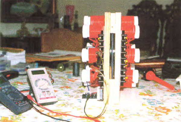
Please allow me to express an important point to everyone. At this time I am only testing the voltage wave and the physical design of one set of coils. Not so much the coils themselves as the relationship between the inducer coils and the induced coil and core. My 3 coils are identical, which does not conform to the design of the old DC generators, and I am a long way from being able to wind a coil intelligently.
I agree if one resistor is used for both coils, but not if he used individual resistors, because at 0 and 180 degrees the two contacts touched by the brush would go to the same resistor, connected to one coil, and the other coil would be mechanically disconnected from the brush. I now suspect he used individual ones because at one point in one of the patents he said 'resistors', if I recall correctly.
Either Figuera or Buford, not sure which, said the secret to the device was the Egg of Columbus. For those not familiar with that reference, he supposedly got an egg to stand on one end by flattening the end of it. When I modeled the commutator rotation, making sure that two adjacent contacts were always touched by the brush, and graphed the voltage changes, the wave was flattened at the min and max range for somewhere between 56 and 69 degrees. Therefore I suspected that this was his egg of Columbus reference. The exact number of degrees depended on the commutator contact width and the brush width. This was verified by my first experiments. Flattening the wave by adding 40ms of 'dwell' at the min and max point increased the voltage output 84%, from 5.0 to 9.2 VAC.
Whether or not a coil goes to absolute 0 volts may be moot, I suspect the flattened wave peaks are much more important.
I have many other ideas to try too. For instance, can two coil sets be constructed from 4 or 5 coils instead of 6? What will happen if I connect two induced coils side by side in series with a common core? Just how many induced coils can be influenced by one pair of inducers? Would they all need to be wound the same?
I hope the information I am posting will be of help to others.
Regards
Hanon, thanks for the tip on amp measuring and testing at 10%. I will do that and let you know. This is all new to me and I have a lot to learn.
Please allow me to express an important point to everyone. At this time I am only testing the voltage wave and the physical design of one set of coils. Not so much the coils themselves as the relationship between the inducer coils and the induced coil and core. My 3 coils are identical, which does not conform to the design of the old DC generators, and I am a long way from being able to wind a coil intelligently.
but a mechanical commutator as the one used by Figuera in 1908 will power at least a little the farest electromagnets.
why did you say that it is important that the signals stay at maximun or minimun for a long time during their oscillation?
Whether or not a coil goes to absolute 0 volts may be moot, I suspect the flattened wave peaks are much more important.
I have many other ideas to try too. For instance, can two coil sets be constructed from 4 or 5 coils instead of 6? What will happen if I connect two induced coils side by side in series with a common core? Just how many induced coils can be influenced by one pair of inducers? Would they all need to be wound the same?
I hope the information I am posting will be of help to others.
Regards


 and it may be very important.
 so he could break the chains around him made by "cut off" theories.
Comment