Announcement

Collapse
No announcement yet.

Re-Inventing The Wheel-Part1-Clemente_Figuera

Collapse
X
 
  • Filter
  • Time
  • Show
Clear All
new posts

  • I believe Tesla knew the exact overunity methods in 1899. His plan was however different to what we look for. He wanted to send energy from one or a few places where the natural energy sources are available. However those are only my suspections because all (if any existed of course) of direct Tesla statements were removed from public knowledge. He found some signs of ou in 1890 or 1891, and definately in 1900 he has the correct concept. Please remember that his main plan was to send power and to create antigravity ships.
    Tesla is the master of riddles, that's for sure.

    Comment


    • Originally posted by Michelinho View Post
      Hi MonsieurM,

      I posted on a great drowser before, l'Abbe Mermet, check it out:
      http://www.energeticforum.com/106318-post102.html

      Take care,

      Michel
      excellent Michelinho .... some new info to digest

      considering :

      rota / introduction to the work of Louis Rota

      The energy flowing within the earth generates a field in the atmosphere. It was tapped by large buried laminated metallic structures which Rota called blocks. The energy could light lamps, power machines, inhibit electromagnetic propagation such as radio waves and stop or control electromagnetic induction
      Merci l'Ami

      a gift for a gift

      Interestingly, London, England's 1912 edition of "Mining Magazine" published the first translation of a Latin Opus into English. It was called "On Metals" in praise of dowsing which had been first published 356 years earlier. The translators were a professional American mining engineer and his wife. The engineer later gained fame and won notoriety as the 31st President of the U.S. -- Herbert Clark Hoover. As Chris Bird notes, "God knows, had President Hoover been an expert dowser himself, he might have predicted, and therefore, prevented the great stock market crash of 1929."
      +

      http://www.gutenberg.org/files/38015...-h/38015-h.htm

      GEORGIUS AGRICOLA
      DE RE METALLICA
      TRANSLATED FROM THE FIRST LATIN EDITION OF 1556

      with

      Biographical Introduction, Annotations and Appendices upon
      the Development of Mining Methods, Metallurgical
      Processes, Geology, Mineralogy & Mining Law
      from the earliest times to the 16th Century
      BY
      HERBERT CLARK HOOVER

      A. B. Stanford University, Member American Institute of Mining Engineers,
      Mining and Metallurgical Society of America, Société des Ingéniéurs
      Civils de France, American Institute of Civil Engineers,
      Fellow Royal Geographical Society, etc., etc.
      AND
      LOU HENRY HOOVER

      A. B. Stanford University, Member American Association for the
      Advancement of Science, The National Geographical Society,
      Royal Scottish Geographical Society, etc., etc.

      1950

      Dover Publications, Inc.

      NEW YORK
      page 40

      With regard to deflection of branches of trees they say nothing and adhere to their opinion.
      +

      Those interested in the strange persistence of this superstition down to the present day—and the files of the patent offices of the world are full of it—will find the subject exhaustively discussed in M. E. Chevreul's "De la Baguette Divinatoire," Paris, 1845; L. Figuier, "Histoire du Merveilleux dans les temps moderne II.", Paris, 1860; W. F. Barrett, Proceedings of the Society of Psychical Research, part 32, 1897, and 38, 1900; R. W. Raymond, American Inst. of Mining Engineers, 1883, p. 411. Of the descriptions by those who believed in it there is none better than that of William Pryce (Mineralogia Cornubiensis, London, 1778, pp. 113-123), who devotes much pains to a refutation of Agricola. When we consider that a century later than Agricola such an advanced mind as Robert Boyle (1626-1691), the founder of the Royal Society, was convinced of the genuineness of the divining rod, one is more impressed with the clarity of Agricola's vision. In fact, there were few indeed, down to the 19th Century, who did not believe implicitly in the effectiveness of this instrument, and while science has long since abandoned it, not a year passes but some new manifestation of its hold on the popular mind breaks out.
      Last edited by MonsieurM; 10-29-2013, 12:12 AM.
      Signs and symbols rule the world, not words nor laws.” -Confucius.

      Comment


      • the new world

        Hey Guys

        One last picture, before me and Columbus , set sail for the New World.
        All I see is Ocean.

        Comment


        • Some of the magic is in the air gap measure.

          Originally posted by MonsieurM View Post
          excellent Michelinho .... some new info to digest

          considering :


          Merci l'Ami

          a gift for a gift


          +

          http://www.gutenberg.org/files/38015...-h/38015-h.htm


          +
          Merci pour la lecture. (En train de lire la serie de Bob Moranne par Henri Verne).

          Hi machinealive,

          The gap between the coils.

          As an example, my partner in our common research did buy a somewhat expensive Gaussmeter, and as a proud new owner of one, started to play around with magnets and coils. Taking measures left and right, up and down, in and out, noting the results he was seing in his little black book. One of his experiment was with air gap in opposing magnetic fields. With a specific air gap he saw, noted and replicated many times the same experiment and showing for an opposing magnetic field of 200 Gauss to another magnetic field of the same strenght (200 Gauss) not 400 Gauss but 800 Gauss resulted. I tend to believe what he says because of his rigourous application of the scientific protocol. One thing is that I am sure it is wider than his probe thickness(~1mm). Hope this may help.

          I told this fact once to a member and it seems it was not forwarded to other (He did not believe maybe) or at least I never saw any post later on with mention and It slipped my mind for some times. Getting old and feeling it. But anyway, it might be good to also vary the size of the air gap.

          On this, I bid all g'night,

          Michel
          http://www.youtube.com/watch?v=jeYscnFpEyA

          Comment


          • Originally posted by Michelinho View Post
            Merci pour la lecture. (En train de lire la serie de Bob Moranne par Henri Verne).

            Hi machinealive,

            The gap between the coils.

            As an example, my partner in our common research did buy a somewhat expensive Gaussmeter, and as a proud new owner of one, started to play around with magnets and coils. Taking measures left and right, up and down, in and out, noting the results he was seing in his little black book. One of his experiment was with air gap in opposing magnetic fields. With a specific air gap he saw, noted and replicated many times the same experiment and showing for an opposing magnetic field of 200 Gauss to another magnetic field of the same strenght (200 Gauss) not 400 Gauss but 800 Gauss resulted. I tend to believe what he says because of his rigourous application of the scientific protocol. One thing is that I am sure it is wider than his probe thickness(~1mm). Hope this may help.

            I told this fact once to a member and it seems it was not forwarded to other (He did not believe maybe) or at least I never saw any post later on with mention and It slipped my mind for some times. Getting old and feeling it. But anyway, it might be good to also vary the size of the air gap.

            On this, I bid all g'night,

            Michel
            Thanks for this info. It should be take into account. if you have further info it will be great.

            Machinealive, How are you going to get the 2 phase AC supply?

            Good luck!!!!
            https://figueragenerator.wordpress.com/

            Comment


            • Originally posted by Michelinho View Post
              Merci pour la lecture. (En train de lire la serie de Bob Moranne par Henri Verne).


              found also the following :

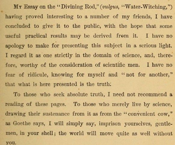
              https://archive.org/stream/diviningr...ge/n7/mode/2up

              THE DIVINING- ROD:

              VIRGULA DIVINA-BACULUS DIVINATORIUS

              (WATER-WITCHING.)


              By CHARLES LATIMER,

              Civil Engineer.


              "There are more things in heaven and earth, Horatio, than are
              dreamt of in your philosophy.' 1 — Shakespeare.


              also :

              Hi machinealive,

              The gap between the coils.

              As an example, my partner in our common research did buy a somewhat expensive Gaussmeter, and as a proud new owner of one, started to play around with magnets and coils. Taking measures left and right, up and down, in and out, noting the results he was seing in his little black book. One of his experiment was with air gap in opposing magnetic fields. With a specific air gap he saw, noted and replicated many times the same experiment and showing for an opposing magnetic field of 200 Gauss to another magnetic field of the same strenght (200 Gauss) not 400 Gauss but 800 Gauss resulted. I tend to believe what he says because of his rigourous application of the scientific protocol. One thing is that I am sure it is wider than his probe thickness(~1mm). Hope this may help.

              I told this fact once to a member and it seems it was not forwarded to other (He did not believe maybe) or at least I never saw any post later on with mention and It slipped my mind for some times. Getting old and feeling it. But anyway, it might be good to also vary the size of the air gap.

              On this, I bid all g'night,

              Michel
              Lockheed Martin Anti-gravity Boyd Bushman Apollo 15 Hammer-Feather Drop - YouTube .... rock experiment

              you can either adjust the air gap or the Magnetic Field ( scalable )


              also the most intriguing of his Inventions ( he spent a bit of time writing about it )


              Tesla valve - Wikipedia, the free encyclopedia

              A Tesla Valve is a valve allowing for a fluid to flow very preferentially (or entirely) in one direction, but without the moving parts usually found in valves. The principle is that currents flow along different paths in different directions, and that these differences have a disproportionate effect on the resistance of the valve. Named after Nikola Tesla, it was invented in 1916 (U.S. patent 1,329,559; patented 1920). In practice, the idea has seen little development or use since its invention. A similar mechanism is used for mixing on a small scale through the use of a Coanda effect mixer.
              Tesla Patent 1,329,559 - Valvular Conduit

              why did he not mention it ( Valvular Conduit ) in the fountain patent or mention the fountain in this Patent ( will have to double check )

              Editor, Scientific American:

              Engineers attach no importance whatever to static electricity generated by belt friction or otherwise. They are apt to dismiss it with the thought that the energy is infinitesimal. That is true. A little water pumped through some joint in a big low-pressure main is of no consequence, but in a pump designed for an extremely high pressure and very small delivery it is all-important. Exactly so in the electrical case. The belt or equivalent device is simply a pump capable of forcing the minute quantity of electricity produced into a condenser against a pressure and increasing the power up to a limit of working capacity of the means employed. Thus mechanical energy, in any desired amount, can be transformed into electric energy yielding direct and constant currents of many millions of volts

              Nikola Tesla Writes (Additional Comments on Electro-Static Generators) from Scientific American, April, 1934.
              Last edited by MonsieurM; 10-29-2013, 02:17 PM.
              Signs and symbols rule the world, not words nor laws.” -Confucius.

              Comment


              • The key is already been given to us long time ago. Tesla called this Rotating Magnetic Induction Machine=Rotating Transformer/Converter=Electro Dynamic Induction Machine.Tesla had use cleverly the Law of Induction Machine on his Motors/Converters/Transformer.
                Tesla called this device on a simple term- Egg of Columbus.

                All your confusion will be clear ones you will understand the concept behind this device.I think its time to revive this thread again, I already posted this before but nobody seems to take interest.

                I know exactly the TPU, Barbosa and Leal Device, Tariel Kapanadze Lenzless Converter,Stanley Meyer VIC,Don Smith Toroid Devices,Clemente Figuera, works exactly the same with this principles.

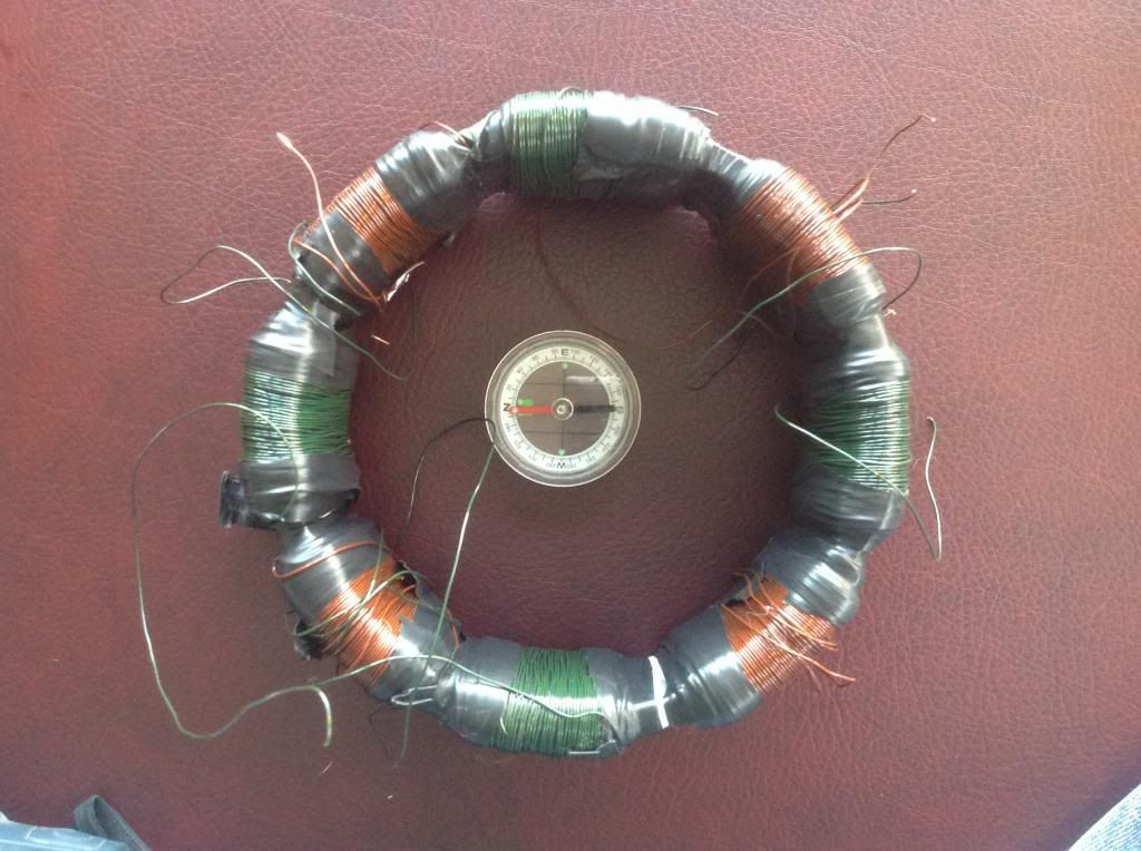
                The Electro Dynamic Induction Machine is wound with 4 coils groups with as 2 sets. Basically we have two Primaries that each primary is wound diametrically opposite with two Coils= 180deg apart on annular ring.

                The power supply could be AC and DC.

                On DC Supply we need a reversing polarity controller on each coil. We will use the 4 Terminal of the two set of coils on DC Supply. We will need a 4 sequence flip flop switching on this to simulate and replicate the action of an Alternating Current.

                On AC Supply we need a TWO phase Alternating Current Generator.We will use only 3 Terminal of the two set of coils, they share common Ground on the 3rd Terminal/Post.

                Operation. Lets say: COIL A and COIL B. Lets device this on a 4 quarter cycle.

                1. 1st quarter cycle. COIL A(the LEFT-[Positive] AND RIGHT-[Negative] wound coil) is now on maximum magnetic strength, energizing the annular ring fixing the magnetic force of lines 90 Degrees. Now the Magnetic Compass(Pointer) inside the annular ring will point 12 O'clock.

                2. 2nd quarter cycle. COL B(The TOP-[Positive] and Bottom-[Negative] wound coil) is now powered by the 2nd phase/lines of supply=flip flop. Is now on maximum magnetic strength while the COIL A is minimum magnetic field.Energizing the annular ring fixing the magnetic force of lines 90degrees. Now the Magnetic Compass(Pointer) inside the annular ring will move to point 3 O'Clock.

                3. 3rd quarter cycle. COIL A(LEFT-[Negative] and RIGHT-[Positive] is again maximum magnetic strength but in reverse polarity.Energizing the annular ring fixing the magnetic force of lines 90 degrees. Now the Magnetic Compass(Pointer) inside the annular ring will point 6 O'clock. COIL B on this quarter is minimum strength which means OFF.

                4. 4th quarter cycle. COIL B(TOP-[Negative] and BOTTOM-[Positive] is again on its maximum magnetic strength but in reverse polarity. Energizing the annular ring fixing the magnetic force of lines 90Degress. Now the Magnetic Compass(Pointer) inside the annular ring will point 9 O'clock. And lastly repeat the 1st quarter cycle to fully turn or move the magnetic rotation of the Magnetic Compass(Pointer).

                I already wanted to reach this to you before. But no one is interested until a man name machinealive had interest on the Rotating Magnetic Field/Rotating Transformer.He is the one you should thank for he encourage me to post this on this thread. I already give you everything which some has keep as secret. But there is no such thing as new on their invention, the new to this people is using their common sense. There is another form of operation this device that I am still looking for I have not perfectly deduce the magnetic field interactions/magnetic field of lines. Post you opinion and suggestion with pictures is much better.

                This device when properly understood is somewhat you guys call the LENZLESS Generator. Don't limit yourself with using only 1 coil windings. Imagination is your limit.I think I have now clear all your confusion.

                Background of this Concept.

                Read all if you wanted to understand it very much.Please focus on Transformer illustration and drawings. Remember it is powered with TWO Phase Alternating Current Generator. The Induction Motor of Nikola Tesla is the same with this Electro Dynamic Induction Machine/Converter. Some times you can see 4 sets of wire powering this Motor or Converter. You can also see 3 wires with common ground of the two phase alternating generator.

                Tesla Patent 381,968 - Electro-Magnetic Motor

                Tesla Patent 382,280 - Electrical Transmission of Power

                Tesla Patent 390,413 - System of Electrical Distribution

                Tesla Patent 382,282 - Method of Converting and Distributing Electric Currents

                Tesla Patent 381,970 - System of Electrical Distribution

                Tesla Patent 390,414 - Dynamo-Electric Machine
                Stupify,
                I have been studing your proposal. I have some questions, maybe dumb questions, but I could find the answer into the patents, at least with my limited understan ding of the concepts :

                - I suppose that the secondary coils are wound over the primary coils. Am I right?

                - How must we wind the secondary coils? The same direction as the primaries ? Should we connect those coils in series?

                - Could you explain why do you say that the toroid is a lenzless generator? If the secondary coils are wound around the toroid then the opposing induced magnetic field (back emf) will oppose the inducer field. Is there any piece that I am missing?

                I have found this patent. What do you think of that?
                Thanks again!!


                Machivealive,
                How are going your tests? I am anxious for watching your compass rotating!! Good luck and keep the good work!!

                Regards
                https://figueragenerator.wordpress.com/

                Comment


                • Originally posted by Michelinho View Post
                  ..... Taking measures left and right, up and down, in and out, noting the results he was seing in his little black book. One of his experiment was with air gap in opposing magnetic fields. With a specific air gap he saw, noted and replicated many times the same experiment and showing for an opposing magnetic field of 200 Gauss to another magnetic field of the same strenght (200 Gauss) not 400 Gauss but 800 Gauss resulted. I tend to believe what he says because of his rigourous application of the scientific protocol......l
                  Very interesting. I remember J. Bedini mentioning same anomlay. (sorry can't remember the exact source). He states that if the gap between permanent magnets on wheel and electromagnet being active - repelling - there is 4 times magnetic strenth. This being true below a certain gap size. I remeber te be well below 1mm.
                  JS
                  Experts spend hours a day in order to question their doing while others stopped thinking feeling they were professionals.

                  Comment


                  • Originally posted by Michelinho View Post
                    ....
                    As an example, my partner in our common research did buy a somewhat expensive Gaussmeter, and as a proud new owner of one, started to play around with magnets and coils. Taking measures left and right, up and down, in and out, noting the results he was seing in his little black book. One of his experiment was with air gap in opposing magnetic fields. With a specific air gap he saw, noted and replicated many times the same experiment and showing for an opposing magnetic field of 200 Gauss to another magnetic field of the same strenght (200 Gauss) not 400 Gauss but 800 Gauss resulted. I tend to believe what he says because of his rigourous application of the scientific protocol. One thing is that I am sure it is wider than his probe thickness(~1mm). Hope this may help.
                    ...
                    Michel
                    Hi Michel,

                    Reading your above mail I recall a very similar measurement somebody showed in an old yahoo mail group, I cannot remember who it was many years ago but I managed to find the drawing he made from his measurements, see the attached file.
                    It seems he did not use any air gap between the two ferrite (ceramic) magnets when probed the field with his Gauss meter. First he probed the magnets separately, then the two in attraction, and then in repulsion.
                    Probably the lack of the air gap between the poles causes the lack of the the 4 times flux appearing, so he measured about twice the flux.

                    rgds, Gyula
                    Attached Files

                    Comment


                    • Hi gyula,

                      Thanks for the picture. I recall John Bedini mentioning the opposing pole magnets setup on his 10 coils monopole but don't recall him saying he was doing it for the multiplied (2X) magnetic field strength but for the resulting sharp North pole. I did a SSG 2 years ago with this setup, it worked well.

                      Take care,

                      Michel
                      http://www.youtube.com/watch?v=jeYscnFpEyA

                      Comment


                      • Based on My Investigation of Polyphase Transformer

                        Originally posted by hanon1492 View Post
                        Stupify,
                        I have been studing your proposal. I have some questions, maybe dumb questions, but I could find the answer into the patents, at least with my limited understan ding of the concepts :

                        - I suppose that the secondary coils are wound over the primary coils. Am I right?

                        - How must we wind the secondary coils? The same direction as the primaries ? Should we connect those coils in series?

                        - Could you explain why do you say that the toroid is a lenzless generator? If the secondary coils are wound around the toroid then the opposing induced magnetic field (back emf) will oppose the inducer field. Is there any piece that I am missing?


                        Regards
                        The Secondary Coils are wound on top of the Primary, but what ever you wanted to wound this coils will still work.

                        The direction of windings of the Secondary Coils are the same with the Primary Coils. Look closely how Tesla wound the Secondary Coils and follow the direction of the Thicker coil the same with the Thinner Primary Coils. All Coils Primary and Secondary started with CW- like a counter clockwise flow of 4 wound coils on the Ring.

                        The 4 Secondary can be connected in series, parallel, multiple arcs. anything you wanted to do with the connection can be done.

                        This is what happen on the Toroid based on my understanding. There are 8 points that happen in the toroid to fully whirl the magnetic field on the Toroid.

                        1. The Left and Right Primary turns ON with the help of the Commutator design by Nikola Tesla. The Generator he used is a DC Magneto Generator, converting the DC to AC with that commutator.

                        2. The Left and Right, The Top and Bottom- Before the Top and Bottom turn ON, The commutator first connect all the coils. The Two Primaries here are fully induced before it fully change to the Top and Bottom magnetic Field.

                        3. The Top and Bottom - are now fully turn ON.

                        4. The Top and Bottom, The Left and Right- all together turns On first before it fully turn ON the Left and Right Primary with the reverse polarity.

                        5. The Left and Right- then proceed after the two primaries are induced, The left and right Primary are fully induced with the Reverse Polarity.

                        6. Left and Right, Top and Bottom- The two primaries together are induced with the Reverse Polarity before it proceed to Top and Bottom reverse polarity.

                        7. The Top and Bottom Primary- are now fully induced with the Reverse Polarity of the supply source.

                        8.Repeating the first 1/8 on step 1.

                        "In producing a shifting of the poles in a Transformer, and thereby inducing currents,the induction is of the ideal character,being always maintained at its maximum action. It is also reasonable to assume that by shifting of the poles less Energy will be wasted than by Reversals." -Quote from the Tesla Book.

                        The inventions, researches and writings of Nikola Tesla, with special reference to his work in polyphase currents and high potential lighting

                        If you understand what I was talking here. The bemf is being suppress on the middle of changing the Primary. The Two Primaries are being induced. Like UFO and Me always told you " Chase me if you can on this Toroid".

                        There is also another way of Tesla's method of In Phase Generator=Lenzless Generator. But I think I will keep that with me.

                        Meow
                        Last edited by stupify12; 11-01-2013, 12:02 PM.

                        Comment


                        • Originally posted by stupify12 View Post
                          The Secondary Coils are wound on top of the Primary, but what ever you wanted to wound this coils will still work.

                          The direction of windings of the Secondary Coils are the same with the Primary Coils. Look closely how Tesla wound the Secondary Coils and follow the direction of the Thicker coil the same with the Thinner Primary Coils. All Coils Primary and Secondary started with CW- like a counter clockwise flow of 4 wound coils on the Ring.

                          The 4 Secondary can be connected in series, parallel, multiple arcs. anything you wanted to do with the connection can be done.

                          This is what happen on the Toroid based on my understanding. There are 8 points that happen in the toroid to fully whirl the magnetic field on the Toroid.

                          1. The Left and Right Primary turns ON with the help of the Commutator design by Nikola Tesla. The Generator he used is a DC Magneto Generator, converting the DC to AC with that commutator.

                          2. The Left and Right, The Top and Bottom- Before the Top and Bottom turn ON, The commutator first connect all the coils. The Two Primaries here are fully induced before it fully change to the Top and Bottom magnetic Field.

                          3. The Top and Bottom - are now fully turn ON.

                          4. The Top and Bottom, The Left and Right- all together turns On first before it fully turn ON the Left and Right Primary with the reverse polarity.

                          5. The Left and Right- then proceed after the two primaries are induced, The left and right Primary are fully induced with the Reverse Polarity.

                          6. Left and Right, Top and Bottom- The two primaries together are induced with the Reverse Polarity before it proceed to Top and Bottom reverse polarity.

                          7. The Top and Bottom Primary- are now fully induced with the Reverse Polarity of the supply source.

                          8.Repeating the first 1/8 on step 1.

                          "In producing a shifting of the poles in a Transformer, and thereby inducing currents,the induction is of the ideal character,being always maintained at its maximum action. It is also reasonable to assume that by shifting of the poles less Energy will be wasted than by Reversals." -Quote from the Tesla Book.

                          The inventions, researches and writings of Nikola Tesla, with special reference to his work in polyphase currents and high potential lighting

                          If you understand what I was talking here. The bemf is being suppress on the middle of changing the Primary. The Two Primaries are being induced. Like UFO and Me always told you " Chase me if you can on this Toroid".

                          There is also another way of Tesla's method of In Phase Generator=Lenzless Generator. But I think I will keep that with me.

                          Meow
                          If you are referring to the converter at the bottom of this patent drawing Patent US390721 - Best available cop - Google Patents
                          then it is not a generator it is a transformer or converter. A converter can be
                          used as part of a generator but .... it then acts as any motor or generator would.

                          Tesla specifically mentions that the motors and generators based on the
                          toroid and rotating magnetic field at the top and the left of the patent
                          drawing all operate in a similar way to the regular motors in that when the
                          load is light the resistance is increased to limit the current flow, and also the
                          reverse that when the load is increased the resistance is decreased and much
                          current flows, all thanks to our good friend Lenz's Law. If not for Lenz's law
                          maximum current based on Ohms law would happen at all times when the
                          devices were powered and no one wants that. Even still nothing would be
                          free.

                          That info is also in the book you linked. If I need to I will quote sections from that book also.

                          I suggest read it once then read it again after you actually build a converter
                          and test it. I did.

                          A step down converter/transformer is not a generator.

                          Cheers

                          Comment


                          • Originally posted by Farmhand View Post
                            If you are referring to the converter at the bottom of this patent drawing Patent US390721 - Best available cop - Google Patents
                            then it is not a generator it is a transformer or converter. A converter can be
                            used as part of a generator but .... it then acts as any motor or generator would.

                            Tesla specifically mentions that the motors and generators based on the
                            toroid and rotating magnetic field at the top and the left of the patent
                            drawing all operate in a similar way to the regular motors in that when the
                            load is light the resistance is increased to limit the current flow, and also the
                            reverse that when the load is increased the resistance is decreased and much
                            current flows, all thanks to our good friend Lenz's Law. If not for Lenz's law
                            maximum current based on Ohms law would happen at all times when the
                            devices were powered and no one wants that. Even still nothing would be
                            free.

                            That info is also in the book you linked. If I need to I will quote sections from that book also.

                            I suggest read it once then read it again after you actually build a converter
                            and test it. I did.

                            A step down converter/transformer is not a generator.

                            Cheers
                            Farmhand good reading you

                            just out of curiosity .... what if you wanted to turn that converter into a generator ... would it be possible or it just needs a source to convert ( plug and play )
                            Last edited by MonsieurM; 11-01-2013, 03:22 PM.
                            Signs and symbols rule the world, not words nor laws.” -Confucius.

                            Comment


                            • talking about valve .... Another Great Inventor mentions' it ( from: http://www.energeticforum.com/242474-post4985.html )


                              Chapter 10

                              Capture of Energy by Resonance


                              [p. 241] Such an energy transformer or converter has been built. It has been operated, at full load continuously with no expenditure of fuels of any type, without a mechanical prime mover, kept alive by the oscillations of the energies from the cosmos; an energy converter, or transformer, which would be capable of converting the high frequency, high level energy of the cosmic radiation into current of usable frequency and voltage.

                              Basically the theory of operation is as follows: Oscillations are started in the first stage or circuit of the device by exciting it with an external energy source. The circuit is "tuned" until the oscillations are sustained by harmonic coupling to the cosmic wave frequencies. The reinforcing action of the harmonic coupling increases the amplitude of the oscillations until the peak pulses "spill" over into the next stage through a special detector or valve which prevents the return or feedback of energy from succeeding circuits. These "pulses" drive this stage, which oscillates at a lower frequency and is again reinforced by harmonic coupling with the ever present cosmic waves. The second stage drives a third stage, and additional stages are coupled until a suitable power level at a useable frequency and voltage is obtained by means of special transformers (See schematic drawing of RE device)

                              Thomas Henry Moray: The Sea of Energy ~ Excerpts of technical factoids & illustrations of the Moray Radiant Energy Receiver.

                              Originally posted by MonsieurM View Post

                              also the most intriguing of his Inventions ( he spent a bit of time writing about it )


                              Tesla valve - Wikipedia, the free encyclopedia


                              Tesla Patent 1,329,559 - Valvular Conduit


                              to tune a circuit to cosmic energy you need first to eliminate insects ( see Faraday Cage )


                              +


                              I have found that, be enveloping a patient in a high potential, high frequency field in such a manner that no closed circuit is completed through his body, radioactive and other electronic and radiation phenomena can be used therapeutically with considerably greater effectiveness than if used alone.

                              Faraday cage - Wikipedia, the free encyclopedia


                              The exact reason for this is not known, nor is it known definitely which, the electric field or the radioactive phenomena, acts upon the other to produce the advantageous results. It is thought, however, that the electric field permeating the body of the patient as it does attracts the radioactive emanations or radiations and enables them to penetrate considerably deeper into the tissues and vital organs of the patient than would otherwise be the case.


                              In any event, remarkable therapeutic results have been achieved by use of the invention in the treatment of malignant tumors. Arthritis, sinus infections, and various other diseased conditions

                              Thomas H. Moray: Transmutation of Low Grade Ores by High Energy Bombardment.
                              Last edited by MonsieurM; 11-01-2013, 11:30 PM.
                              Signs and symbols rule the world, not words nor laws.” -Confucius.

                              Comment


                              • ps: Thomas Henry Moray started his projects while working for a Mining company


                                read the previous post with the following in mind :

                                rota / introduction to the work of Louis Rota

                                During one of these experiments he touched the Stabilisiteur and received an enormous electric shock which rendered him unconscious for 50 minutes. Rota said that the voltages and currents used in the machine were very small and he could not understand how a potential of such a large magnitude build up ( in a trap ). The search for a solution, ultimately lead him to the discovery of the Universal Current. This unknown energy, he thought, had amplified the small electric current used in the machine.
                                . The energy flowing within the earth generates a field in the atmosphere. It was tapped by large buried laminated metallic structures which Rota called blocks. The energy could light lamps, power machines, inhibit electromagnetic propagation such as radio waves ( same as Faraday Cage ) and stop or control electromagnetic induction, and also develop antigravity effects and is involved in the life process
                                +

                                While the light was burning Mr Moray disconnected the antenna lead-in wire from the apparatus and the light went out. He connected it again and the light appeared. He also disconnected the ground wire and the light went out. He then connected it and the light appeared again."

                                .... see also The Tom Bearden Website

                                Tesla's Single Wire Circuit and Energy Shuttling
                                Thomas Henry Moray: The Sea of Energy ~ Excerpts of technical factoids & illustrations of the Moray Radiant Energy Receiver
                                and both had to "tune" their respective circuit/ Antenna ( rota used earphones )
                                Last edited by MonsieurM; 11-02-2013, 12:53 AM.
                                Signs and symbols rule the world, not words nor laws.” -Confucius.

                                Comment

                                Working...
                                X