Announcement

Collapse
No announcement yet.

Re-Inventing The Wheel-Part1-Clemente_Figuera

Collapse
X
 
  • Filter
  • Time
  • Show
Clear All
new posts

  • Induction by "flux cutting" or by "flux linking"

    Richard Feynman (Nobel prize winner) about the electromagnetic induction:

    "So the "flux rule" that the emf in a circuit is equal to the rate of change of the magnetic flux through the circuit applies whether the flux changes because the field changes or because the circuit moves (or both) ...

    Yet in our explanation of the rule we have used two completely distinct laws for the two cases  E = v x B  for "circuit moves" and  E = -S· dB/dt  for "field changes".

    We know of no other place in physics where such a simple and accurate general principle requires for its real understanding an analysis in terms of two different phenomena.

    ...

    The "flux rule" does not work in this case [note:an example in the original text]. It must be applied to circuits in which the material of the circuit remains the same. When the material of the circuit is changing, we must return to the basic laws. The correct physics is always given by the two basic laws


    — Richard P. Feynman, The Feynman Lectures on Physics

    --------------------------------------------

    For those interested in a interesting fact about the Induction Law here I link a file which explains that two different formulations seem to exist for the same phenomenon : one, the Faraday Unipolar generator: E = (v · B) , other the Maxwell 2nd Law : rot E = -dB/dt, which are two different formulations for the same law !!! Faraday-or-Maxwell by Meyl (read page 5 and next of the file)

    https://figueragenerator.wordpress.com/

    Comment


    • Cutting and Linking

      Are they not the same thing?
      That is, just magnetic fields interacting with each other regardless of poles?
      Just wondering.
      artv

      Comment


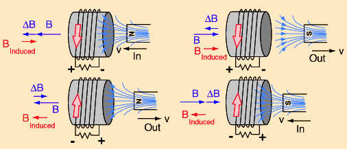
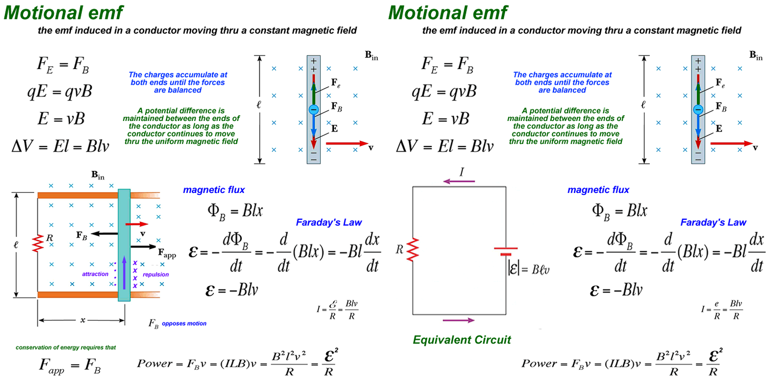
      • Also there are two different manifestation of Lenz Law:

        1- Lenz Law derived from a flux linking two coils
        : It will create a opposing magnetic field (Binduced) against the change in the original magnetic field


        2- Lenz Law derived from a flux cutting the moving wire
        : it will appear a dragging force (F_b) which oppose the movement.


        A proof of this dragging force can be seen here in a coil perpendicular to the inducer field: Video

        Therefore: even in a coil at right angle to the inducer field we will get a dragging effect, although we can skip the opposing magnetic field. But we still have the dragging force against the movement..

        Maybe the idea behind Figuera devices was to move the flux lines to cut the wire instead of moving the wire to cut the flux lines. This way you could skip both the opposing magnetic field and the dragging force. I don´t know. I am still learning ...
        https://figueragenerator.wordpress.com/

        Comment


        • Maxwell talks a lot about the screw mechanism of the field, hence the rotE is for rotation as I understand it.

          Comment


          • The way I see it...

            Hello Guys,

            Interesting posts and information!...Monsieur and you Hanon...are incredible restless and endless researchers !

            I see Magnetism more from a Dynamic point of view, and could even say from an "Artistic Perspective"...rather than with rigid math formulas and straight vectors...Magnetic Fields flow, expand, propagate into our 3D Space in unlimited and endless directions...if we were to calculate each as rigid vectors...not even the Sum generated by complicated High Level Algebra...like Integers for adding non regular 3D Volumes, even considering Infinite Limits...will not suffice to satisfy their constant changes...influenced by so many external and internal factors within materials exposed to them...

            [IMG][/IMG]

            [IMG][/IMG]

            For example in the Figures above (and want to say that I am not happy either with this rigid 2D Images, If I had the time...I would build all this in MAYA 3D and Animate this with Dynamics and flows as Cameras travel 360º around volumes...but unfortunately I don´t...so I would limit to my lousy English...and a simple 2D Fixed Image to describe the different waves, currents in a moving, dynamic Ocean...)

            On that Fig...I set two black arrows, indicating the movement of the Magnet related to the Coil, one comes from inside the Coil traveling outwards...the other relates to the way we obtain induction in typical generators rotation of the exciting fields into the generating coils...The point is...that no matter to where I move that magnet through that coil...such movement will generate some flows in the 3D Space.

            "The Induced Flow"

            The Main Flow created would be what we call the Induced Field...I represented it by that flow of red curved lines with red arrows coming from the back end of coil and projecting towards magnet...this generates a type of a "polarity screen" depicted by red and blue transparent planes...and of course the South (Red) would be attracted by the magnet blue-North Face.

            Looking at it in "another way"...We could say that the proximity of that magnet towards that coil... starts a series of alignments of all particles floating around the 3D Space of coil, where Coil becomes like a "Gate", a Door, between a "Space" , a Dimension we can not see...can not feel, or touch...This excitement of aligned particles set them in specific points of that space...and when magnet or magnetic field starts a movement...those aligned particles will start a "displacement" following the path that magnetic field would take...and of course...if the leading magnetic pole towards that coil and aligned particles would be a North...it is understood the closest particles generated by that flow would be of opposite nature...meaning South, in this case...so the Highest "concentration" of South Particles would "linger", float at the closest point-space of that North Magnetic Field.

            "The Electric Field Flow"

            The other Flow generated by the "Induced Field" that was, at same token, provoked by the movement of the magnet...would be the one that is generated around the Copper Conductor atomic structure...and it is like a Spinning, using as axis each wire section...I "painted them" as those circular, multiple, black arrowed arcs contouring the whole coil...but notice they follow same "winding path" as the Main Induced Flow... except they "stay" circling conductor surface.

            The Electrical Flow

            This Multiple Rotations, spinning around the copper electronic structure...will generate a main flow within the Coil conductor central section...say from Positive side to Negative end...which is our Energy flowing out of coil conductor...picture multiple screws...rotating around wire...and generating a forward flow, according to screw rotation.

            Now, it would be understood...that if we close loop that coil (like that video you showed above, Hanon) then the electrical flow will keep strengthening for every additional movement of the exciter field...therefore, creating an increase of the Induced Field Potential...deriving in a much stronger opposed field...then drag is at maximum rate...just like when we load a Generator...the load is actually short circuiting those coils.

            Finally...notice how in that video...when the coil is shorted...falls like in "slow motion"?...it does not matters that fields are perpendicular...still, there would be space interactions from both fields...and there would be drag.

            On the experiment of an Aluminum or a Copper Tube...dropping a cylindrical magnet...and watch it fall in a complete slow motion...why?...drag, magnetic drag of all those Coil flows I pictured , described above... will also manifest on solid round paramagnetic materials (Aluminum) or Good Electrical Conducting materials like Copper...


            This is the way I see and feel... all this magnetic phenomena , known as Induction, could possibly occur...


            Regards


            Ufopolitics
            Principles for the Development of a Complete Mind: Study the science of art. Study the art of science. Develop your senses- especially learn how to see. Realize that everything connects to everything else.― Leonardo da Vinci

            Comment


            • Hi all,

              Maybe the real configuration of the Figuera´s patent is with like poles facing each other.


              My impression is not clearly in favor or against this view because the only sentence in the 1908 patent where it is defined the poles orientation is written as follows: "Let`s suppose two electromagnets represented by the rectangles N and S". Nothing more and nothing less. Maybe it was just a "patent notation" trick to hide the real pole orientation.

              Suppose two like poles facing each other and with their flux lines repepling and swinging back and forth along the changes in intensity in the electromagnets. Those flux lines cross partially the central induced coil and also cut the induced wire during his swinging motion up and down.

              As you can see in this scheme there is induction by 2 mechanisms:
              1. Induction by Flux linking along the part of each coil transversed by the flux lines
              2. Induction by Flux cutting the induced wire


              We could have both types of induction into the same device.The key in this scheme is that the induction by flux cutting to be greater than the induction by flux linking. (the flux linking induction is under the Lenz Law effect and will produce an opposing induced magnetic field which will reduce the inducers strength)

              The good part of this idea is that if the flux cutting induction by an N-N configuration will induce in the sense to reduce the inducers field (due to the Lenz effect), then the S-S configuration will do it in the sense to increase it because the flux lines in each case have opposite direction (from inside-out or from outside-in).


              Any comments?
              Last edited by hanon1492; 01-10-2017, 12:37 AM.
              https://figueragenerator.wordpress.com/

              Comment


              • Are you referring to the following Schematic


                I would refer you to a previous post :

                on Lockheed Martin Anti-gravity Boyd Bushman Apollo 15 Hammer-Feather Drop - YouTube

                the rock experiment was hinting at the same configuration N - N / S - S

                you also have to consider he may have alternated N - N then S- S , N- N etc....

                my 2 cents
                Signs and symbols rule the world, not words nor laws.” -Confucius.

                Comment


                • Magnets in motion

                  Hi Hanon, I don't see it , how there can be 2 types of induction.?
                  Two magnets opposing each other ,but being forced together, and putting a coil in there.
                  Unless you could time , or induce when the sides of the coil are being induced.
                  A coil is round , one side see's the flux-lines first, so it gets induced (atoms spin in 1 direction). The other side start to follow that spin , but since the magnetic pole is in motion, and starts to leave the 1st side and induce the 2nd side , the first side now creates an opposite flow?
                  The north will cause a south, which in turn will cause a north,....so on and so on......
                  artv

                  Comment


                  • TRANSLATION OF KEY PARTS OF BUFORN PATENT No. 57955 (1914) (text extracted from pages 12,13 and 14) (link)

                    By using a magnetic field, consisting of two series of electromagnets N and S, a resistor and a circumference of contacts isolated from each other .....
                    ...
                    Note that only the contacts located in the Northern semicircle are in communication with half of the end sides of each resistor, and the contacts in the Southern semicircunference are not in communication with the resistor, but respectively with the contacts in the semicircle communicated with half of the end sides of each resistor, and inasmuch as the current moves on the the magnetic field and returns from it by the input and output sides of the resistor, and as this field is composed of two series of electromagnets N and S , therefore, and as result of the operation of the device when the electromagnets N are full of current, the electromagnets S are empty, and as the current flowing through them is reducing or increasing in intensity according it passes by more or less turns of the resistor, and therefore, in continuous variation; since we have done a continuous and organized variation we have achieved a constant change in the current which crosses the magnetic field formed by the electromagnets N and S and whose current, after completing their task in the difrerent electromagnets, returns to the source where it was taken.
                    ...
                    We have already achieved to produce the continuous and organized change of the intensity of the current which crosses the magnetic field.
                    ....
                    The way to collect this current is so easy that it almost seems excused to explain it, because we will just have to interposed between each pair of electromagnets N and S, which we call inducers, another electromagnet, which we call induced, properly placed so that either both opposite sides of its core will be into hollows in the corresponding inducers and in contact with their respective cores, or either, being close the induced and inducer and in contact by their poles, but in no case it has to be any communication between the induced wire and the inducer wire.
                    ....
                    Another advantage is that around the core of the induced electromagnets we can put another small size induced electromagnet with equal or greater core length than the large induced one. In these second group of induced an electric current will be produced , as in the first group of induced, and this produced current will be sufficient for the consumption in the continuous excitation of the machine, being completely free all the other current produced by the first induced electromagnets in order to use it in all purposes you want.


                    Why does he call it "Northern semicircle"? It is curious how Buforn defines that the "Northern semicircle" is in communication with the resistor but not the "southern semicircle", don´t you think so?. Please see the attached picture. It seems that the he places the North in the upper part of the sketch (as usually happens in maps). If so, the electromagnets may be are labelled according to their orientation: N facing North and S facing South ...If so, then both electromagnets would be facing each other with like poles... Just an idea....I really don´t know

                    Regards
                    https://figueragenerator.wordpress.com/

                    Comment


                    • Poles

                      I haven't seen that patent ,but will look it up.
                      I've found in many testes , the north pole of the magnet always reacts with more abruptness, when being influenced by an artificial magnetic field, created by electron flow (batteries, current flow).
                      I'm currently at a stand still ,because I have the two fields fighting.
                      My switch isn't fast enough, and my pulse isn't strong enough, or my coil isn't big enough, timing or frequency whichever ,that's the answer.
                      artv

                      Comment


                      • The Way I see it...

                        Originally posted by hanon1492 View Post
                        TRANSLATION OF KEY PARTS OF BUFORN PATENT No. 57955 (1914) (text extracted from pages 12,13 and 14) (link)

                        By using a magnetic field, consisting of two series of electromagnets N and S, a resistor and a circumference of contacts isolated from each other .....
                        ...
                        Note that only the contacts located in the Northern semicircle are in communication with half of the end sides of each resistor, and the contacts in the Southern semicircunference are not in communication with the resistor, but respectively with the contacts in the semicircle communicated with half of the end sides of each resistor, and inasmuch as the current moves on the the magnetic field and returns from it by the input and output sides of the resistor, and as this field is composed of two series of electromagnets N and S , therefore, and as result of the operation of the device when the electromagnets N are full of current, the electromagnets S are empty, and as the current flowing through them is reducing or increasing in intensity according it passes by more or less turns of the resistor, and therefore, in continuous variation; since we have done a continuous and organized variation we have achieved a constant change in the current which crosses the magnetic field formed by the electromagnets N and S and whose current, after completing their task in the difrerent electromagnets, returns to the source where it was taken.
                        ...
                        We have already achieved to produce the continuous and organized change of the intensity of the current which crosses the magnetic field.
                        ....
                        The way to collect this current is so easy that it almost seems excused to explain it, because we will just have to interposed between each pair of electromagnets N and S, which we call inducers, another electromagnet, which we call induced, properly placed so that either both opposite sides of its core will be into hollows in the corresponding inducers and in contact with their respective cores, or either, being close the induced and inducer and in contact by their poles, but in no case it has to be any communication between the induced wire and the inducer wire.
                        ....
                        Another advantage is that around the core of the induced electromagnets we can put another small size induced electromagnet with equal or greater core length than the large induced one. In these second group of induced an electric current will be produced , as in the first group of induced, and this produced current will be sufficient for the consumption in the continuous excitation of the machine, being completely free all the other current produced by the first induced electromagnets in order to use it in all purposes you want.


                        Why does he call it "Northern semicircle"? It is curious how Buforn defines that the "Northern semicircle" is in communication with the resistor but not the "southern semicircle", don´t you think so?. Please see the attached picture. It seems that the he places the North in the upper part of the sketch (as usually happens in maps). If so, the electromagnets may be are labelled according to their orientation: N facing North and S facing South ...If so, then both electromagnets would be facing each other with like poles... Just an idea....I really don´t know

                        Regards

                        Hello Hanon,


                        The way I understand it...

                        [IMG][/IMG]

                        Buforn is showing Us a 2D Planar Projection of what it is in reality a 3D Model.

                        The "Northern Semicircle" I created a Blue Arc depicting it in above Image...as the "Southern semicircunference" I highlighted in Red.

                        Now, this is the upper part of a 3D Cylinder or Drum...

                        So, the Green Rectangle I marked, is just the "Half Vertical Wall" of that cylinder, contouring-exactly 180º- that "Northern Semi-circle"... Buforn cut it and spread it flat on a 2D Plane in order to show Us the Resistors alignment and connections.

                        Yeah, but do not think this is all...

                        The number of "LINEAR Alignments" or Columns of Electromagnets N-S PLUS the "Induced"...are Eight...right?...So, He does again, same procedure by spreading what is a cylindrical volume of Electromagnets aligned into a flat 2D Planar Figure.

                        Now, go to the left lower small circle, split in how many parts?...Eight right?

                        I believe that small circle, split in eight equal parts, indicates where the Right Figure of Electromagnet-Coils-Cores, vertically aligned, are positioned Within the Inner Drum Space, but taking the whole 360º.

                        Something like Figure below:

                        [IMG][/IMG]

                        Can You guys picture all this in 3D?

                        I will try to make a 3D Model, whenever time allows me to ...

                        Regards


                        Ufopolitics
                        Last edited by Ufopolitics; 11-21-2013, 03:25 AM.
                        Principles for the Development of a Complete Mind: Study the science of art. Study the art of science. Develop your senses- especially learn how to see. Realize that everything connects to everything else.― Leonardo da Vinci

                        Comment


                        • Hi Ufo, it is always a pleasure to have your help!!!

                          I guess what you are proposing but I can not see the advantage of this new arrangement. Is there any change in the interconnection between the resistors and the electromagnets?

                          I have always wonder why the number of resistors (8), the number of stages in the conmutator (8) and the number of groups of electrmagnets (8) match so perfectly. [Note that in the original 1908 Figuera patent he only used 7 groups of electromagnets as the only noticeable difference to Buforn´s scheme]. In the 1908 patent is written that "the resistor is drawn in a simple way to make easier the understanding of the concept". Possible there is something under those coincidences...

                          I have read many times that patent and in the text it is very well explained the operation of the conmutator and the changes in the current. The only things that are not so well explained is the poles orientation (as I posted the last days) ("Let us suppose two series of electromagnets represented by the rectangles N and S and an induced circuit represented by the line 'y'" (small) "), the orientation of the induced coil ("a induced circuit properly placed") and the electrmagnets shapes ("because nothing moves the electromagnets do not need to be round"). IMHO I think that in those sentences is hidden the key of the patent. I can not guess why Figuera explained so well some concepts and then he left these sentences so undefined...

                          Regards

                          PS Ufo, in yor sketch the circle in the left upper part I think that it should have the same color matching as the big conmutator because both are in the same orientation.
                          Last edited by hanon1492; 11-21-2013, 11:15 PM.
                          https://figueragenerator.wordpress.com/

                          Comment


                          • Hello Hanon

                            Originally posted by hanon1492 View Post
                            Hi Ufo, it is always a pleasure to have your help!!!

                            I guess what you are proposing but I can not see the advantage of this new arrangement. Is there any change in the interconnection between the resistors and the electromagnets?
                            Hello Hanon, thanks

                            Hanon, I am not proposing anything new related to the way the circuit is attached, same exact thing...
                            Therefore, the Electromagnets are connected the same way as Diagram to the resistors.

                            I have always wonder why the number of resistors (8), the number of stages in the conmutator (8) and the number of groups of electrmagnets (8) match so perfectly. [Note that in the original 1908 Figuera patent he only used 7 groups of electromagnets as the only noticeable difference to Buforn´s scheme]. In the 1908 patent is written that "the resistor is drawn in a simple way to make easier the understanding of the concept". Possible there is something under those coincidences...
                            I am sorry if my posts above have created any more confusion on this Thread!...It is just the way I picture this...as it is the first time I give my opinion on this Buforn Patent (I did it before on the Figuera's Dynamic Generator) So I am not familar if anyone has made a Geometrical Projection-set up of this before on the Thread.

                            Related to the Physical arrangement of the Electromagnets and the Induced Coils ...look at it the simple way...He places on each column a North and a South Electromagnet, and "sandwiched" in between, are the Induced Coils, so, here I am sure, the way he meant it (because of the missing clarity to show both poles for each electromagnet), I deduct He is only showing Interacting Poles, just like we all do also in Motors and Generators Conventions...So Induced Coil is in between a North and a South Field.

                            If You notice He uses a small "Bar like" rectangle that travels from all three elements (N Exciter, S Exciter and Induced Coil) in each column...In my opinion that bar denotes a "mechanical attachment"...something like a "Bracket" to support all three elements as a structure. But again...we are "guessing" here, since there is no reference to those little bars.

                            Related to the way exciter electromagnets are Electrically connected between them...is not shown, just have the connection to resistors...as the connections to the rotary contactor switch or "Delga" in Spanish or Commutator switch. We then "deduct" they are connected in series, and the small box on right lower means contacts are open as in a "register electrical box"

                            Therefore, in each column, this two coils (exciters) are set in a way to "Induce" each center coil(induced), except, there is no movement nor change in the fields setting them just like that alignment...So, they use the resistors attached to the exciting fields to create in a "Dual Way" a Synchronization of effects

                            1- A change in Current passing Both exciter coils (N-S) when rotary contacts touch different stages.

                            2- A Change in the Exciters Magnetic Fields strength consequence or dependent of 1


                            I have read many times that patent and in the text it is very well explained the operation of the conmutator and the changes in the current. The only things that are not so well explained is the poles orientation (as I posted the last days) ("Let us suppose two series of electromagnets represented by the rectangles N and S and an induced circuit represented by the line 'y'" (small) "), the orientation of the induced coil ("a induced circuit properly placed") and the electrmagnets shapes ("because nothing moves the electromagnets do not need to be round"). IMHO I think that in those sentences is hidden the key of the patent. I can not guess why Figuera explained so well some concepts and then he left these sentences so undefined...

                            Regards

                            PS Ufo, in yor sketch the circle in the left upper part I think that it should have the same color matching as the big commutator because both are in the same orientation.
                            Speaking of this Patents, my friend, and being familiar with all the Patent Graphic Design Requirements in US and now International codes...and I tell you, honestly, this patents (both, Figuera and Buforn) are extremely generally written as very poorly drawn, as no details, no numbered parts, not a fair and detailed description of the preferred embodiments...no perspective or isometric views,etc,etc

                            Just look at a Tesla Patent big difference...He mentions and number even the attaching bolts and nuts...following the International Patent Rules...

                            This facts brings us to make a lot of "assumptions"...and different interpretations as anyone could look at it in a different "fashion"...making it harder to come up to a common meeting and conclusions.

                            And You know I can handle both languages (Spanish and English)...so language is not the issue here, nor translations either...your job has been excellent!.


                            Regards


                            Ufopolitics
                            Principles for the Development of a Complete Mind: Study the science of art. Study the art of science. Develop your senses- especially learn how to see. Realize that everything connects to everything else.― Leonardo da Vinci

                            Comment


                            • Maybe simpler?

                              Hi Hanon and UFO

                              I think Figuera made it vague enough so you could not copy his work and broad enough to cover a few configurations, this is the writing/drawing of someone keen on protecting his work. UFO is right in looking at it with his expertise, just as 100 others have made different versions, I can only add to another version myself. The Figuera will be Figured and a Figure will be Finalized, LOL, Regards Arto.

                              Comment


                              • Hello Artoj!

                                Originally posted by artoj View Post
                                Hi Hanon and UFO

                                I think Figuera made it vague enough so you could not copy his work and broad enough to cover a few configurations, this is the writing/drawing of someone keen on protecting his work. UFO is right in looking at it with his expertise, just as 100 others have made different versions, I can only add to another version myself. The Figuera will be Figured and a Figure will be Finalized, LOL, Regards Arto.
                                Hello Artoj!

                                Nice and very clean drawings!...You should lend it to Buforn for a new and MUCH better application!...

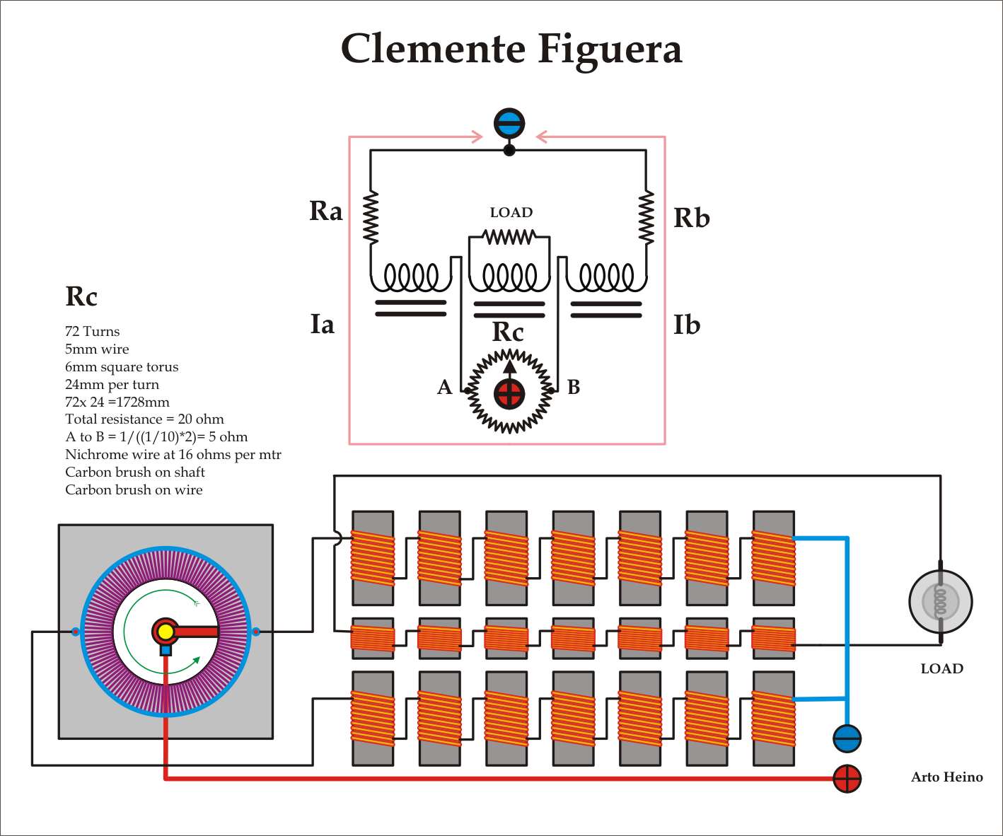
                                I see you are simplifying all resistors as a Toroidal winding with Ni-chrome wire (just like an expensive "Rheostat" or a Wound Potentiometer....BRAVO! Yes, I agree with you there.

                                I also agree with you on the Load Hook from the induced coils all connected in series (we are both assuming that also, since Figuera or Buforn do not show it), but it is simple common sense...adding the energy in series, rather than paralleling coils...

                                There are just a couple of things...that do not agree with Patent Drawing/Connections:

                                1- Patent shows that Resistors only comprehend the "Northern Semi-circumference" or 180º, and not rounding the whole 360º like your Toroid does. Even though, your concept makes more sense to me than his...but well...it is their Patent, not ours...
                                Then Buforn refers to the "Southern Semi-Circle":
                                ...and the contacts in the Southern semicircunference are not in communication with the resistor, but respectively with the contacts in the semicircle communicated with half of the end sides of each resistor
                                So, like I wrote before...He then shows an isolated Diagram on top Left (that to me looks like a spider with legs touching like in a Ballet position...or the Nazca Paintings "The Spider"...just kidding...)...Resuming, I believe this is what he is referring to, in reference as connection of the Southern Semi-Circle with the Northern one...

                                2-Your Positive (+) and Negative (-) as Input/Feed for Brush and Exciter Coils...Buforn only draws a small box...not even open wires like He does with Load wires out...

                                And last...Why would they take their time to draw resistors within a Box, following almost same pattern (as spaced apart between them and depth or length) and same number in columns (8) as electromagnets/Inducted Coils Columns alignment...?

                                Below is my corrected Diagram as Hanon pointed out previously on my error on that Spider on left upper (Yes, completely right Hanon )

                                [IMG][/IMG]

                                And below is the Spider connections from Southern Semicircle with Northern one in just one Diagram.:

                                [IMG][/IMG]


                                I believe we are getting "warmer" (closer) every time more on this Generator Riddle...

                                Good work !


                                Regards


                                Ufopolitics
                                Last edited by Ufopolitics; 11-23-2013, 05:32 AM.
                                Principles for the Development of a Complete Mind: Study the science of art. Study the art of science. Develop your senses- especially learn how to see. Realize that everything connects to everything else.― Leonardo da Vinci

                                Comment

                                Working...
                                X