Announcement

Collapse
No announcement yet.

Re-Inventing The Wheel-Part1-Clemente_Figuera

Collapse
X
 
  • Filter
  • Time
  • Show
Clear All
new posts

  • phase shift

    (note: one phase length is viewed as a full circle or 360 degrees, as the signal then repeats)

    Hi hanon1492
    as far as I can follow your reasoning in post #714 I think most points of your deductions are correct.
    However, your image correctly depicts the required phase shift between the signals of the two primary coils. This phase shift is half a phase length, which is also called a phase shift of 180 degrees or in other words "phase inversion", "phase opposition" or "counter phase".

    Why do you talk about 90 degrees phase delay in your last post? I think 180 degrees is correct.
    Last edited by marxist; 12-23-2013, 06:21 AM.

    Comment


    • Hi marxist,
      Good question. My idea to use a Thomson Ring, 90 phase shift, is related to the last scheme in the previous picture.

      Suppose that you feed the Thomson Ring with AC, you will get a 90° unphased signal. If you later on take both signals into two diodes brigdes you will rectify them into a doble positive wave with a period half of the original period. Both signals will be now 180° unphased as the last type of signal drawn in my previous sketch.

      Regards
      Last edited by hanon1492; 12-23-2013, 12:18 PM.
      https://figueragenerator.wordpress.com/

      Comment


      • Hi all,

        I have collected into a single PDF file my last ideas about an overunity generator as we have been discussing lately.

        Regards,
        Hanon1492

        Link to the PDF file

        Other link to the PDF file
        Attached Files
        Last edited by hanon1492; 01-02-2014, 11:12 AM.
        https://figueragenerator.wordpress.com/

        Comment


        • I do not know how to link pictures with a post, so I am just placing the
          links below. Link 1 is for a 555 circuit, Link 2 is for house electrical
          connection, and Link 3 is for fifty different 555 circuits.

          In the picture in Link 1, the top 555 Sinewave output picture might help.
          The output is similar to a sinewave, but it is above 0 volt. If using a 12 volt
          suppply, the output would be about 11 volts and up to 200 mA. The output
          would need to be raised somehow.

          Link 2 shows how U.S. houses are connected to the grid. In the top left side
          you will notice that the input to the transformer is split on the secondary,
          and the wave forms are "out of phase" by 180 degrees.

          If you take the output from the 555 chip, amplify it, use a RC low
          pass filter to get a sinewave, then use a transformer that has a split
          secondary, would that work?

          Link 1:
          http://www.talkingelectronics.com/pr.../555-Osc-1.gif

          Link 2:
          Household Electric Circuits

          Link 3:
          50 - 555 Circuits
          THE SIMPLEST 555 OSCILLATOR
          The simplest 555 oscillator takes output pin 3 to capacitor C1 via resistor R1.
          When the circuit is turned on, C1 is uncharged and output pin 3 is HIGH. C1
          charges via R1 and when Pin 6 detects 2/3 rail voltage, output pin 3 goes LOW.
          R1 now discharges capacitor C1 and when pin 2 detects 1/3 rail voltage, output
          pin 3 goes HIGH to repeat the cycle. The amount of time when the output is HIGH
          is called the MARK and the time when the output is LOW is called the SPACE.
          In the diagram, the mark is the same length as the space and this is called 1:1
          or 50%:50%. If a resistor and capacitor (or electrolytic) is placed on the output,
          the result is very similar to a sinewave.

          IMPROVING THE SINKING OF A 555
          The output of a 555 goes low to deliver current to a load connected as shown in the
          circuit below. But when the chip is sinking 200mA, pin 3 has about 1.9v on it. This
          means the chip does not provide full rail voltage to the load. This can be improved by
          connecting pin 7 to pin3. Pin 7 has a transistor that connects it to 0v rail at the same
          time when pin 3 is LOW. They can both be connected together to improve sinking
          capability. In this case the low will be 800mV for 200mA instead of 1900mV, an
          improvement of 1100mV. This will add 1v1 to the load and also make the chip run
          cooler.

          Hope some of this might help,
          Bob

          Comment


          • Originally posted by hanon1492 View Post
            Hi all,

            I have collected into a single PDF file my last ideas about an overunity generator as we have been discussing lately.

            Regards,
            Hanon1492

            Link to the PDF file

            Other link to the PDF file

            Thanks Hannon, you have obviously put some time in here.
            I have already saved to print all your diagrams and explanations, but it is nice to have it organised.

            Thanks again, and Merry Christmas Everybody,

            Warmest Regards Cornboy.

            Comment


            • Tesla already showed us!

              Originally posted by hanon1492 View Post
              Hi all,

              I forget to clarify that the two opposite signals must change the intensity field but it is not neccesarry to reverse polarity.

              Both signals must be always above zero voltage.


              Regards
              Nice going guys. I see that you still have a hard time analyzing what Tesla showed on his Generators/Converters. Ufo already showed you how Tesla wound his generator to evade the lenzlaw effect.

              Tesla showed this simple fact on his way of windings coil on his Generator, that the Induced coils Opposing magnetic Field will happen when his Generator coils is on a Neutral position away from the Magnetic fields of North and South, I am talking here on a device with Magnets. By that way Tesla could produce electricity on his Generators with out Drag only assisting of opposing magnetic field on the Induced Generating Coils when The terminal output of the Generating Coils is short circuit/closed circuit.

              Then this is how you will figure it out. That Tesla device is using a solid Magnets, how can you do it when you apply it on a Electromagnet Coils?

              Tesla showed it on his 4 wound coils toroid transformer,Tesla called it a combination of Motor and Generator.

              This is the correct configuration for electromagnet Coils. Two Inducing Coils/Two Primary, 4 Magnetic Poles that are arranged to result only to TWO Magnetic Poles= North+ North= x2 North and South+South= x2 South .

              All you have read and understand here all correct, about the law of induction it is still the most fundamental law. But Tesla found a novel way by his design/arrangement that it doesn't break the Law of Induction but avoiding the so called Third Law of Motion=Opposing Force.

              Please read and understand how did Tesla design he's Generator its all there, then the next stage was the 4 wound coils which actually still the same with hes Generator, He created a virtual Magnetic Field that rotates(Motor) while at the same time cutting the copper wire with it magnetic lines of force(Generator).

              How can u say the word of lenz effect if the Inducing Magnetic Field and the Induced Magnetic Field doesnt oppose each other but assist?

              Comment


              • Hi Stupify,

                Nice to see you. I said that the induced field assist the inducer field because if you see the sketch with the electromagnets and their lines of force you may note that the resulting induced vector field ADD to the inducers vectors. In this configuration, the induced current flows in the direction to create a field which reinforce the changes in the inducers field (dB/dt). Therefore this field is incresing (assisting) the effect iniciated by the electromagnets. In a sense, this generator magnify the initial perturbation.

                Regards
                Last edited by hanon1492; 12-25-2013, 12:46 PM.
                https://figueragenerator.wordpress.com/

                Comment


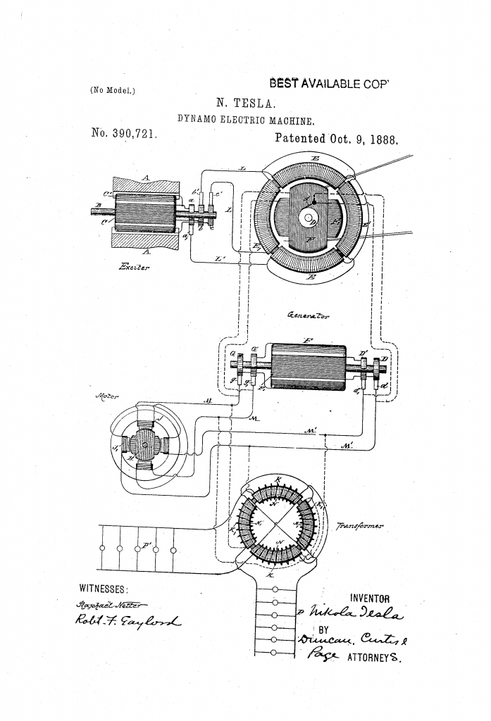
                • This arrangement pictured below is explained well by Tesla in this book. And it
                  reads to me that the setup obeys Lenz's law to the letter.

                  I do not see how it was said to be otherwise. I suggest to begin reading from page 41.

                  https://ia700302.us.archive.org/16/i...00martiala.pdf

                  The effective strength of the currents developed in the armature
                  coils of the generator is dependent upon the strength of the
                  currents energizing the generator and upon the number of rotations
                  per unit of time of the magnetic poles of the generator
                  ;
                  hence the speed of the motor armature will depend in all cases
                  upon the relative speeds of the armature of the generator and of
                  its magnetic poles.

                  It will be observed in connection with this system that on
                  diminishing the resistance of the external circuit of the generator
                  armature by checking the speed of the motor or by adding
                  translating devices in multiple arc in the secondary circuit or circuits
                  of the transformer the strength of the current in the armature
                  circuit is greatly increased
                  . This is due to two causes : first,
                  to the great differences in the speeds of the motor and generator,
                  and, secondly, to the fact that the apparatus follows the analogy
                  of a transformer, for, in proportion as the resistance of the armature
                  or secondary circuits is reduced, the strength of the currents
                  in the field or primary circuits of the generator is increased and
                  the currents in the armature are augmented correspondingly.

                  For similar reasons the currents in the armature-coils of the
                  generator increase very rapidly when the speed of the armature
                  is reduced when running in the same direction as the magnetic
                  poles or conversely.
                  And the Patent image says "Best available Copy" not "Best available C.O.P."
                  the "Y" didn't come out from the stamp when it was stamped "Best available Copy".


                  So my question is where is this setup of Tesla's that Tesla said was "Lenz-less" ?


                  ....

                  As we can read and see the input to this device is relative to the output.

                  The input is the mechanical power applied to drive the "Exciter" and the mechanical
                  power applied to the "drive belt" to drive the Armature.

                  If more devices are added and more output is drawn then more input is required as Tesla clearly states.

                  This is basically just a "wound rotor" induction motor used as an AC generator.

                  When more power is drawn, the Armature will require more mechanical force
                  to try to keep turning it at the same speed.

                  The strength of the output currents depends on both the strength of the
                  currents through the field coils from the exciter (Which needs to be spun as an alternator)
                  in order to excite the field coils, and the rate at which the armature is spun (requiring force as well).

                  All adhere to Lenz's Law. Lenz's Law is just an observation, it is not something
                  that people enforce on devices, it is what is seen to happen, explained as a "Law".


                  ....
                  Last edited by Farmhand; 12-26-2013, 02:20 AM.

                  Comment


                  • And further back towards the end of page 20 beginning of page 21 he explains the action of the motors/generators as below.

                    Source document.
                    https://ia700302.us.archive.org/16/i...00martiala.pdf

                    In many respects these motors are
                    similar to the continuous current motors. If load is put on, the
                    speed, and also the resistance of the motor, is diminished and
                    more current is made to pass through the energizing coils,
                    thus
                    increasing the effort
                    . Upon the load being taken off, the
                    counter-electromotive force increases and less current passes
                    through the primary or energizing coils
                    .
                    Without any load the
                    speed is very nearly equal to that of the shifting poles of the
                    field magnet.
                    Thank goodness for Mr Lenz and counter emf, it is because of them that when
                    the load is removed the input does not remain maximum, but in fact it reflects
                    the load as a practical and efficient arrangement should.

                    ..

                    Without counter emf or the effect described by Lenz's Law the machine would
                    not be usable. It would fly apart or catch fire from overspeed or overheat
                    respectively.

                    ..

                    The only machine I can think of that Tesla himself describes as being relatively counter emf free
                    is a very specially designed "Unipolar" machine page 468, and
                    that device required a particular configuration to achieve that.

                    Considered as a dynamo machine, the disc is an equally interesting
                    object of study. In addition to its peculiarity of giving
                    currents of one direction without the employment of commutating
                    devices, such a machine differs from ordinary dynamos in
                    that there is no reaction between armature and field. The armature
                    current tends to set up a magnetization at right angles to
                    that of the field current, but since the current is taken off uniformly
                    from all points of the periphery, and since, to be exact,
                    the external circuit may also be arranged perfectly symmetrical
                    to the field magnet, no reaction can occur
                    . This, however, is
                    true only as long as the magnets are weakly energized, for when
                    the magnets are more or less saturated, both magnetizations at
                    right angles seemingly interfere with each other
                    .

                    For the above reason alone it would appear that the output of
                    such a machine should, for the same weight, be much greater
                    than that of any other machine in which the armature current
                    tends to demagnetize the field. The extraordinary output of the
                    Forbes unipolar dynamo and the experience of the writer confirm
                    this view.

                    ...
                    Last edited by Farmhand; 12-26-2013, 03:01 AM.

                    Comment


                    • Originally posted by hanon1492 View Post
                      Hi all,

                      There is a spanish patent about a overunity generator filed in 1955 by David Hogan and carlos Ludovik Jakovlewich (patent ES225316) which is curiously very very similar to the Figuera patent No. 303376 , the one with the rotary drum coil. In this patent the coil is stationary and the magnets are mounted over some rotating discs.

                      I have translated the claims of this patent:


                      ---------------------
                      CLAIMS SPANISH PATENT ES225316

                      The authors claim in this patent:

                      1) New electric generator characterized by the existence of series of discs, variable in number and in dimension, susceptible to host "magnets".

                      2) New electric generator according to claim 1 characterized in that the series of discs are mounted on a shaft in parallel arrangement ; the shaft rests on its sides over bearings. This arrangement of supporting bearings allow its intermediate extension if required.

                      3 ) New electric generator according to claims 1 and 2,wherein the " magnets " located in the discs must be placed parallely on the shaft. These discs, spaced, will allow that the poles of the magnets ( magnetos) of each disc are facing " north-south " (opposition of poles).

                      4) New electric generator according to claims 1 to 3, characterized in that between the discs (series of two) a stationary or fixed screen or sieve (grids) of copper wire or any electroconductive material glazed and covered with insulation is placed.

                      ----------------------------------
                      In the description it is clearly stated that the authors are describing an overunity generator where a part of the energy produced could be used to power the machine and the rest could be used externally for other uses.

                      Any comments?


                      Patent in pdf


                      Although the Hogan Jakovlewich patent is off topic from Figuera generator I think I have devised a way to place the induced grid. The configuration I want to show is as follows:
                      1- The wires are static. The magnets are rotating. Therefore the dragging force into a conducting wire (Lorentz force: F= I·Length·B, which opposes the movement) won´t be able to create any drag into the wires because they are static.

                      2- The whole disc surface must be covered by the same pole. One disc will be North in its whole area and the opposite disc is South in its whole area. The field will rotate but will not change in intensity nor in polarity.

                      3- The induced grid must be one layer RADIALLY placed with a conducting rim in the periphery. The current will flow radially toward the rim creating a center simetry. Therefore there won´t be any coil formed which could oppose the magnets' field. Thus, no opposing magnetic field will be created.


                      Note: The grid just need one peripherical rim. The internal rims are not needed. I have not found any picture with just the external rim.

                      Regards
                      Last edited by hanon1492; 12-26-2013, 03:42 PM.
                      https://figueragenerator.wordpress.com/

                      Comment


                      • same thing

                        Originally posted by hanon1492 View Post
                        As far as I understand there are two effects opposing the current generation:

                        1- The Lenz effect which produce a opposing magnetic field reducing the magnets field

                        2- This dragging force (Lorentz Force)
                        Hi hanon1492,
                        these are not two effects.
                        These are just two aspects of one physical phenomenon.

                        or in other words: the Lorentz Force is causing the Lenz effect.
                        Last edited by marxist; 12-28-2013, 07:38 AM.

                        Comment


                        • Hi,
                          I am not sure if both effects are the same phenomenon or they are two different phenomena. Please check this old post about a discussion about this same subject:

                          http://www.energeticforum.com/renewa...tml#post243329

                          Richard Feynman:"We know of no other place in physics where such a simple and accurate general principle requires for its real understanding an analysis in terms of two different phenomena."
                          https://figueragenerator.wordpress.com/

                          Comment


                          • Originally posted by marxist View Post
                            (note: one phase length is viewed as a full circle or 360 degrees, as the signal then repeats)

                            Hi hanon1492
                            as far as I can follow your reasoning in post #714 I think most points of your deductions are correct.
                            However, your image correctly depicts the required phase shift between the signals of the two primary coils. This phase shift is half a phase length, which is also called a phase shift of 180 degrees or in other words "phase inversion", "phase opposition" or "counter phase".

                            Why do you talk about 90 degrees phase delay in your last post? I think 180 degrees is correct.
                            Hi marxist.
                            I am glad that somebody else noticed that as well
                            I have been saying that it's 180 degree shift from the beginning of this discussion.
                            But others stubbornly tried to convince me the other way.
                            You can even tell by the discrepancies in the graphics provided:
                            top 3 graphs are taken from my post and the bottom one is their (hanon & bajac) interpretation (half-sines are colored differently).
                            I am still saving money for a 2 channel scope for my experiments to continue.
                            C'mon Guyz! Let's make this thing work!
                            Cheers
                            “ THE PERSON WHO SAYS IT CANNOT BE DONE SHOULD NOT INTERRUPT THE PERSON DOING IT ! ”

                            Comment


                            • Hi,

                              The key is to use two opposite signals: while one signal is increasing the other signal must be decreasing about the same quantity. As I described in my previous posts I think that Figuera was trying to move the lines of forces from one electromagnet to the other by using both signals. I think that the shape of signals is not so important while they are in opposition.

                              We have been labelling these signals with different names depending if the considered period of the signal is a single period or doble (for a rectified AC wave). But all of us have been refering to the same concept: two opposite signals.

                              Proposal for a overunity generator (PDF)

                              Regards
                              https://figueragenerator.wordpress.com/

                              Comment


                              • Originally posted by hanon1492 View Post
                                Hi,

                                I think that the shape of signals is not so important while they are in opposition.

                                Regards
                                Hi.
                                The symmetry of magnetic interaction is required.
                                Rectified sinewaves 90 shifted DO NOT meet those requirement of linear intensity interaction.
                                A triangular ramp shape DOES and DC biased sinewaves in antiphase DO too.

                                I hope you get what I am saying.
                                Last edited by kEhYo77; 12-30-2013, 02:36 AM.
                                “ THE PERSON WHO SAYS IT CANNOT BE DONE SHOULD NOT INTERRUPT THE PERSON DOING IT ! ”

                                Comment

                                Working...
                                X