resistors
Ufopolitics;
Yes sir i do and thank you kindly.
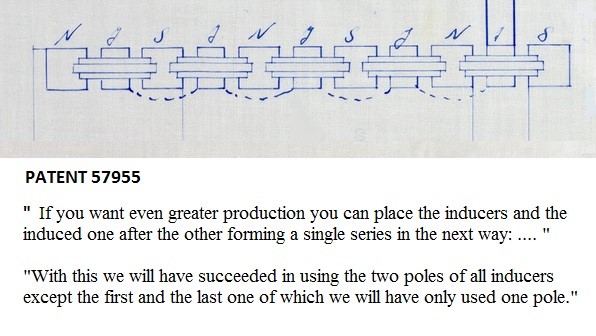
"BUT", if i may add, that the commutator bars and resistor referred to in the patent are actually thick winding's on a core. it says it is, in it's elementary form for understanding and is just a drawing.
i think people are getting confused as the term resistors being referred to on a continuous basis. PJK even states in his book and this incorrect assumption is confusing people when they come here.
part G is actually both in the drawing in its higher form and has many functions, that is why part G can NOT be omitted or replaced.
1. it split the DC currant into two separate feeds.
2. each feed has opposing fields allowing each feed to be varied separately in unison.
3. allows the inductive force from the declining electromagnet being shoved out of the secondary core into it's own core, then to be stored in the core of part G like an inductor to be used at the next half rotation. part G is constantly fed from all declining electromagnets every half turn of the brush.
4. becomes the power supply for the entire system after initial start.
as you can see part G is very valuable to the Figuera device.
also as you might gather part G does not have a lot of winding like a regular variac. in Hanon's video he used a variac with DC and verified this as only a 1/4 turn varied the currant from zero to full.
again i thank you for your post but i think newcomers are being confused at the notion of resistors in this device.
BroMikey; two opposing magnet or electromagnet's will always put out more than a single one will. Walter Russel stated our coils are wound wrong, wasting 50 % E field to magnetism. Figuera figured out how to add that lost 50 % back making it 100 %. no standard generator can touch this level.
PS. if not in opposing mode ie. N/N or S/S double intensity E fields will not form. if using N/S the currants will oppose each other and output will be less than half of the previous stated.
Ufopolitics;
Yes sir i do and thank you kindly.

"BUT", if i may add, that the commutator bars and resistor referred to in the patent are actually thick winding's on a core. it says it is, in it's elementary form for understanding and is just a drawing.
i think people are getting confused as the term resistors being referred to on a continuous basis. PJK even states in his book and this incorrect assumption is confusing people when they come here.

part G is actually both in the drawing in its higher form and has many functions, that is why part G can NOT be omitted or replaced.
1. it split the DC currant into two separate feeds.
2. each feed has opposing fields allowing each feed to be varied separately in unison.
3. allows the inductive force from the declining electromagnet being shoved out of the secondary core into it's own core, then to be stored in the core of part G like an inductor to be used at the next half rotation. part G is constantly fed from all declining electromagnets every half turn of the brush.
4. becomes the power supply for the entire system after initial start.
as you can see part G is very valuable to the Figuera device.

also as you might gather part G does not have a lot of winding like a regular variac. in Hanon's video he used a variac with DC and verified this as only a 1/4 turn varied the currant from zero to full.
again i thank you for your post but i think newcomers are being confused at the notion of resistors in this device.

BroMikey; two opposing magnet or electromagnet's will always put out more than a single one will. Walter Russel stated our coils are wound wrong, wasting 50 % E field to magnetism. Figuera figured out how to add that lost 50 % back making it 100 %. no standard generator can touch this level.
PS. if not in opposing mode ie. N/N or S/S double intensity E fields will not form. if using N/S the currants will oppose each other and output will be less than half of the previous stated.


 But I'm afraid you didn't get my post right?
Comment