Announcement

Collapse
No announcement yet.

Re-Inventing The Wheel-Part1-Clemente_Figuera

Collapse
X
 
  • Filter
  • Time
  • Show
Clear All
new posts

  • part G

    If you wind part G with regular wire like in a regular variac the distance between winding"s (gaps) are huge and will cause rotation problems as part G does not need a large amount of winding's to get currant change. so to alleviate this problem use wider wire so there are no large gaps so the brush will rotate smoothly. if you can find a way around this by all means have at it.

    it has nothing to do with the thickness of the wire in essence just the width that is important. that is part of the reason i chose small toroids then stacked them to get the proper va rating so i have lower winding count.

    again the patent says commutator bars but in reality they are wide winding's on the core.

    just remember to have more headroom then you need of at least 500 va larger then your primaries will consume.

    MM
    Last edited by marathonman; 09-16-2016, 05:50 AM.

    Comment


    • The windings on the "G"-toroid between terminals to N and S needs to be
      CW AND CCW to maintain the inductance in the toroid.
      With all turns CW (or CCW) around the hole toroid NO inductance can be measured between the N ans S terminals or between the rotating connector to any of the N and S parts.

      The Eagle

      Comment


      • PCB Board.

        Well that about raps it up for my timing board for part G. had to change opto-isolators to transistors as they wouldn't push the PNP's. using NPN's to switch on the PNP Power Mosfets.
        below is pic of timing board.


        MM
        Last edited by marathonman; 09-16-2016, 09:53 AM.

        Comment


        • Toroid Continuous Wind Magnetic Field(s)

          Originally posted by seaad View Post
          The windings on the "G"-toroid between terminals to N and S needs to be
          CW AND CCW to maintain the inductance in the toroid.
          With all turns CW (or CCW) around the hole toroid NO inductance can be measured between the N ans S terminals or between the rotating connector to any of the N and S parts.

          The Eagle
          Hello Seaad,

          I am sorry, but that statement above is Negative, the Toroid needs to be wound in Only One Continuous direction:

          [IMG][/IMG]

          This design is a Constant Rotating Floating Positive, injected by either the Brush through commutator (tap connected to specific wires set at equal distances) or directly sweeping wires, or by electronics MOSFET's to each wind. Which splits into two Variable Positive Outputs.

          If You do CW plus CCW winds on the Toroid...you will never achieve the same repeated magnetic fields throughout the whole 360º.

          Between both opposite magnetic polarizations N1-N2 it would be formed a 3D Spatial Center Compressed Magnetic Field (Aqua Center Circle) which would be rotating along the whole circumference of the Toroid.

          For the purposes of the Figuera Device, the bottom half -in black- would be the side which will be constantly receiving the returning currents from the receding Primaries, and you must realize that this black part is also moving along the whole toroid.


          Regards


          Ufopolitics

          EDIT 1: I edited this post related to voltage polarities errors in drawing plus other info, which I considered that could bring confusion for this Thread as it does not relates to Topic.
          Last edited by Ufopolitics; 09-16-2016, 01:20 PM.
          Principles for the Development of a Complete Mind: Study the science of art. Study the art of science. Develop your senses- especially learn how to see. Realize that everything connects to everything else.― Leonardo da Vinci

          Comment


          • Current control

            MM,

            You have stated several times that the current is limited by part G, not the resistance of the inducer coils. Call me a dunce but I can not get my head around this.

            If part G resistance is essentially a autotransformer of relative few turns then what limits the amperage out if not the resistance of the load?

            Regards,
            CM

            Comment


            • Possible problem?

              Originally posted by Cadman View Post
              MM,

              You have stated several times that the current is limited by part G, not the resistance of the inducer coils. Call me a dunce but I can not get my head around this.

              If part G resistance is essentially a autotransformer of relative few turns then what limits the amperage out if not the resistance of the load?

              Regards,
              CM

              Hello Cadman,

              Yes, I also see this as a possible future issue here...

              If the Primaries winding must be very low in resistance, to obtain faster response...less self inductance, as having a high gauge wire...etc...and also the G Toroid have very few turns of such high gauge rectangular wire (higher than Primaries)...meaning this closed circuit would be operating at very, very low resistance values as a whole...therefore, Amperage would be "loose" all the time...a huge short circuit?

              Let's see what MM says about this...


              Regards


              Ufopolitics
              Last edited by Ufopolitics; 09-16-2016, 01:41 PM.
              Principles for the Development of a Complete Mind: Study the science of art. Study the art of science. Develop your senses- especially learn how to see. Realize that everything connects to everything else.― Leonardo da Vinci

              Comment


              • @Ufopolitics
                I made a simple test with a toroid all 360º wound in the same direction. The ends connected together and with a center 180º connection as your pic. (+) ---- (+) Measured (+) to (+) with an inductance meter showing = zero mH. What else can I do??

                Regards Arne
                Last edited by seaad; 09-16-2016, 02:53 PM.

                Comment


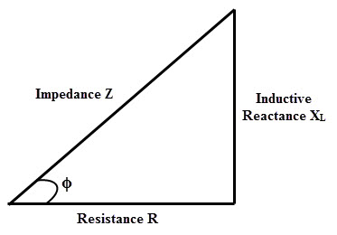
                • I think part G is a variable inductance (L) "governor". Instead of using ohmic resistance to control the current, part G uses the inductive reactance XL = 2•pi•f•L to control the current


                  If you wind part G with regular wire like in a regular variac the distance between winding"s (gaps) are huge and will cause rotation problems as part G does not need a large amount of winding's to get currant change. so to alleviate this problem use wider wire so there are no large gaps so the brush will rotate smoothly. if you can find a way around this by all means have at it.

                  it has nothing to do with the thickness of the wire in essence just the width that is important. that is part of the reason i chose small toroids then stacked them to get the proper va rating so i have lower winding count.
                  MM, I still do not understand why to use so thick wire in your case that you are going to drive it electronically without any brush, just connecting to some intermediate taps. You do not need to be worried by the gaps between turns. If I understood properly that so thick wire is just useful for those installing a brush rotating around the toroid over that wire


                  Seaad, could you elaborate a bit deeper into your post about CW and CCW windings? Thanks. I think you have made your toroidal test in a static circuit with DC input. Therefore your inductance has been 0.0 mH. I think part G, as it is fed by DC, need a dynamic contact around the toroid. If static, it is just a DC appliance wuth zero inductance. Was you test static or dynamic (rotating) in your toroid?
                  Last edited by hanon1492; 09-16-2016, 03:11 PM.
                  https://figueragenerator.wordpress.com/

                  Comment


                  • Originally posted by seaad View Post
                    @Ufopoliics
                    I made a simple test with a toroid all 360' wound in the same direction. The ends connected together and with a center 180' connection as your pic. (+) ---- (+) Measured (+) to (+) with an inductance meter showing = zero mH. What else can I do??
                    Hello Seaad,

                    This Toroid is just a part that is meant to be connected to two primary coils terminals. At simple sight it just Splits the Positive signal from the center of positive main feed. However when it is all connected, it decreases resistance towards the rotation sense, as it increases currents, and the opposite functions (increase R, decrease I) takes place at the other side terminal.

                    This part is meant to have very low resistance as very low inductance.

                    I do not think from positive to positive would give you any readings...since there is no current flow.

                    Look at the way this whole circuit connects:

                    [IMG][/IMG]

                    So, to test Inductance you must connect the common negative to both primaries like shown above, then choose either + outputs to check while rotating the floating positive in different positions.


                    Regards


                    Ufopolitics
                    Principles for the Development of a Complete Mind: Study the science of art. Study the art of science. Develop your senses- especially learn how to see. Realize that everything connects to everything else.― Leonardo da Vinci

                    Comment


                    • Inductance

                      Originally posted by hanon1492 View Post
                      ...
                      If static, it is just a DC appliance wuth zero inductance. ...
                      Hi hanon,

                      A coil will have inductance regardless of AC, DC, or no current, but will have zero reactance with DC (steady state). Inductance becomes a factor only when current changes.

                      bi

                      Comment


                      • Ufo, MM,

                        Something is bugging me.

                        Ufo, in your video TOROIDAL ROTATION SEQUENCE REFLECTED ON PRIMARIES, with N1 connected at 90 and N2 connected at 270 what is going on in the half of the toroid opposite from the rotating brush!
                        I mean, when the brush is between 90 & 270 degrees what is happening in the toroid from 270 to 90 degrees & vice versa? Both electrically and magnetically?

                        Something about this doesn't seem right and I can't put my finger on it. I've seen very old variacs that were wound on EI cores with a fat center leg and the brush rotated on the flat surface. That would be very different from a toroid as shown in the video.

                        Regards,
                        CM

                        Comment


                        • Thoughts

                          Originally posted by Ufopolitics View Post
                          ...

                          [IMG][/IMG]
                          For the purposes of the Figuera Device, the bottom half -in black- would be the side which will be constantly receiving the returning currents from the receding Primaries, and you must realize that this black part is also moving along the whole toroid.

                          ...
                          Hi Ufo,

                          The -in black- (bottom half in the diagram) flip-flops back and forth, top to bottom, pivoting on the 2 + connections. It (in black area) is always opposite the half which is in contact with the wiper (movable brush). And unless the wiper is at 12:00 or 6:00 and the loads are equal, the -in black- windings will be a load on the system wasting power.

                          The inductance (reactance) of this part G will be a factor. In a static condition it may measure zero but as currents change differently in different sections, it is bound to play a roll.

                          A couple of thoughts:

                          Interesting device. I'm curious as to how it would work.

                          It is not your typical variac as those are auto-transformers.


                          Note the non-continuous winding and the common connection (node) input to output.

                          Be it a variac or potentiometer, it will be difficult to make and unlikely to last very long with continuous rotation of the wiper and fairly high RPM. I think you guys would do better using a commercial commutator and brush (including slip rings if needed) which are made for high speed moving contact.

                          Regards,

                          bi
                          Attached Files

                          Comment


                          • Originally posted by Cadman View Post
                            Ufo, MM,

                            Something is bugging me.

                            Ufo, in your video TOROIDAL ROTATION SEQUENCE REFLECTED ON PRIMARIES, with N1 connected at 90 and N2 connected at 270 what is going on in the half of the toroid opposite from the rotating brush!
                            I mean, when the brush is between 90 & 270 degrees what is happening in the toroid from 270 to 90 degrees & vice versa? Both electrically and magnetically?

                            Something about this doesn't seem right and I can't put my finger on it. I've seen very old variacs that were wound on EI cores with a fat center leg and the brush rotated on the flat surface. That would be very different from a toroid as shown in the video.

                            Regards,
                            CM
                            Hello Cadman,

                            The way I understand this...is when Brush is at 90º, meaning N1 is fully fed (direct connection, positive brush to positive terminal output to N1), therefore, N1 magnetic Field is fully expanded, Max strength due to full currents and least resistance, and so the opposite process takes place at the other terminal for N2 Primary, meaning maximum resistance and lowest currents, and if we picture the Field, N2 is "retracting" in this stage. According to MM, the currents from N2 travel back or return to Toroid windings through N2 terminal.

                            And so the opposite process takes place when brush is at N2 Max Out (270º)...where N2 is now at Max Strength.

                            So, directly trying to answer your question...this opposite space to positive brush serves as a "momentary storage" of returning currents from the retracting field stage, until comes the timing to disburse it back.

                            This is just the way I see this process...I really can not describe at this point what is going on in that part of toroid "magnetically" until I start making the proper analysis of the opposite fields versus currents displacements.


                            Regards


                            Ufopolitics
                            Principles for the Development of a Complete Mind: Study the science of art. Study the art of science. Develop your senses- especially learn how to see. Realize that everything connects to everything else.― Leonardo da Vinci

                            Comment


                            • Originally posted by bistander View Post
                              Hi Ufo,

                              The -in black- (bottom half in the diagram) flip-flops back and forth, top to bottom, pivoting on the 2 + connections. It (in black area) is always opposite the half which is in contact with the wiper (movable brush). And unless the wiper is at 12:00 or 6:00 and the loads are equal, the -in black- windings will be a load on the system wasting power.

                              The inductance (reactance) of this part G will be a factor. In a static condition it may measure zero but as currents change differently in different sections, it is bound to play a roll.

                              A couple of thoughts:

                              Interesting device. I'm curious as to how it would work.

                              It is not your typical variac as those are auto-transformers.


                              Note the non-continuous winding and the common connection (node) input to output.

                              Be it a variac or potentiometer, it will be difficult to make and unlikely to last very long with continuous rotation of the wiper and fairly high RPM. I think you guys would do better using a commercial commutator and brush (including slip rings if needed) which are made for high speed moving contact.

                              Regards,

                              bi
                              Hello Bistander,


                              Yes, and like I wrote to Cadman, this black end according to MM serves as a momentary storage of currents, flowing back from the decaying field "in turn" at primaries.

                              Definitively is a part to test first with taps from each turn (or at least as close as possible in an organized fashion) and a commutator brush-slip rings assy...like I have made...

                              I am waiting to see MM finished wired core...as he will tell how many turns it has...in order to get the proper commutator...I have up to 56 elements...so, let's see.

                              I believe this part is just like Hanon mentioned before...a Variable Inductance device. And so, in order to evaluate it properly, we must think it stores currents as magnetic fields in its huge iron core...momentarily (I would say for fractions of seconds) considering going at 3600 RPM's...and like Hanon wrote, it is meant to work on Dynamic State only.

                              Well, you know a Toroid core in solid iron like this, will generate its magnetic fields fully on its internal mass, rather than "spacing" (from Spatial) them out like any normal iron cylinder or other open mass ferromagnetics would. So, I believe a Toroid is chosen because its properties as having the least magnetic losses of all other geometries. Plus a toroid on this job will keep spinning this internal magnetic fields within when this main positive feed would be spinning, as disbursing them out in the form of currents through its outputs.

                              I picture this out as a "Magnetic Pump" actuating two "Magnetic Cylinders" in a Pull-Push timed action.


                              This is just the way I pic this...


                              Thanks


                              Ufopolitics
                              Last edited by Ufopolitics; 09-16-2016, 05:10 PM.
                              Principles for the Development of a Complete Mind: Study the science of art. Study the art of science. Develop your senses- especially learn how to see. Realize that everything connects to everything else.― Leonardo da Vinci

                              Comment


                              • Mass Doubt

                                Hanon;

                                I posted on post #1051 and stated this device acts as an inductor, do people not read.

                                yes as the brush rotates, winding numbers/ core area changes in a dynamic state causing inductive reactance. just like i stated in my post.

                                seaad ;

                                All winding's are the same way, UFOP is correct in his assessment as cw/ccw wound on same core would destroy symmetry of magnetic fields.
                                as currant enters the coil from primaries, opposing field are automatically initiated and respond to the dynamic inductive reactance caused by the rotating brush causing currant reduction.
                                since inductive reactance is created dynamically (on the fly) no inductance will be measured in the coil from low winding single layer count.

                                bistander;

                                you would be incorrect, as my close source stated specifically that after he built part G, ground the contact area, the device had such little wear that he was completely blown away.

                                Part G is a simple device, all though being simplex at the same time. it's multiple roles it plays is testament to Figuera's true genius.

                                it is like no other device i have come across before. i knew some people would have a hard time understanding it's elegant complexities as i have sat for hours upon hours visually studying magnetic field interaction in a dynamic state.

                                UFOP;

                                Quote;
                                "Well, you know a Toroid core in solid iron like this, will generate its magnetic fields fully on its internal mass, rather than "spacing" (from Spatial) them out like any normal iron cylinder or other open mass ferromagnetics would. So, I believe a Toroid is chosen because its properties as having the least magnetic losses of all other geometries. Plus a toroid on this job will keep spinning this internal magnetic fields within when this main positive feed would be spinning, as disbursing them out in the form of currents through its outputs."

                                very correct assumption, i knew we would get along from the first post. your perceptions tend to run a little
                                deeper than most.

                                Think Dynamic Variac.


                                MM
                                Last edited by marathonman; 09-16-2016, 06:23 PM.

                                Comment

                                Working...
                                X