Announcement

Collapse
No announcement yet.

Re-Inventing The Wheel-Part1-Clemente_Figuera

Collapse
X
 
  • Filter
  • Time
  • Show
Clear All
new posts

  • Originally posted by bistander View Post
    Hi Ufo,

    I'm not getting into your argument with other members.
    Ok Bistander, no problems.

    Originally posted by bistander View Post
    I often use a regulated power supply wired in series with a battery and resistor and set the curent regulation to hold a constant current value for the duration of the battery discharge. So obviously current from an external power source can go thru the PSU.
    That is good enough, thanks!

    As we could also set the C.L. (Current Limit) by simply looping both PSU +/- terminals...then adjusting to desired amps...so then PSU will work with just V regulation.

    In your case you are shutting to maintain a constant current related to battery spec's to avoid a discharge...

    Originally posted by bistander View Post
    I hesitate to make a judgment on your test. It appeared as though you had the PSU set to 5A max. The load decreased so voltage on the PSU meter went up. But the current should have been maintained at max of 5A. The fact it went higher or cause is unknown; maybe due to noise. I wonder if putting a sizeable capacitor across the PSU would avoid the problem.

    Regards,

    bi
    Yes, and the way current starts initially to increase... is when I decelerate system...which threw me off completely...and then at very high speeds it went up again...very rare!

    Yeah, but a Cap would then get charged up...will this maintain current stable?

    And the thing is...that I have tried also with my Linear PSU...and did it again.

    Anyways have to keep working...thanks for the reply


    Ufopolitics
    Principles for the Development of a Complete Mind: Study the science of art. Study the art of science. Develop your senses- especially learn how to see. Realize that everything connects to everything else.― Leonardo da Vinci

    Comment


    • I still want to run this test

      Hi MM,

      Welcome back. Please explain how to "observe the currant drop as currant is introduces to the wire".

      Appreciated,

      bi

      Originally posted by bistander View Post
      Originally posted by marathonman View Post
      ...

      the only way to check to see a reasonably accurate test would either be to test the magnetic field around the wire with currant flowing through it or observe the currant drop as currant is introduces to the wire in which i have done.
      ...
      MM
      Hi MM,

      Thanks for the reply. LCR meters do supply a reasonable current for the test. I feel confident in seaad's test. But I would like to duplicate the test you describe and claim to have conducted yourself. Please elaborate as how you were able to measure "the currant drop as currant is introduces to the wire".

      Thanks in advance,

      bi

      Comment


      • Originally posted by Ufopolitics View Post
        Yeah, but a Cap would then get charged up...will this maintain current stable?
        That's the idea. I think it will. Don't go overboard with size. Start medium or small in uF and go up from there if needed. Use a reasonably high Ohm discharge resistor. Cap V rating above your max PSU voltage.
        Last edited by bistander; 01-06-2017, 09:59 PM. Reason: Typo

        Comment


        • Testing

          I used two amp meters from a friend of mine which will hold peak and lows with 10 turns of each wire on an iron core. as i introduced voltage and currant to the wire from an 10 amp source, i recorded the amperage at peak and at low and what i observed was higher induction from the wider wire then that of the regular round wire.
          it was from that test that i decided to use wider wire and also from the other reasons i posted on continuum.

          i have never said that regular wire will not work just many more turns with a deeper core.

          while i am well aware this test may not be the ideal test it will suffice for me but as i have observed you in action you will go plum nutz on my results ranting i didn't do it correctly or some other more ridiculous claim but i really don't care to hear it from a non builder or a status quo'er.

          so please take it as you will as MY TESTS ARE SIMPLY THAT, MY TESTS.
          if you have a better way then by all means DO IT, I'M GOOD.

          Good day Mr Bistander.

          MM
          Last edited by marathonman; 01-06-2017, 05:02 PM.

          Comment


          • Ammeter

            Originally posted by marathonman View Post
            I used two amp meters from a friend of mine which will hold peak and lows with 10 turns of each wire on an iron core. as i introduced voltage and currant to the wire from an 10 amp source, i recorded the amperage at peak and at low and what i observed was higher induction from the wider wire then that of the regular round wire.
            it was from that test that i decided to use wider wire and also from the other reasons i posted on continuum.

            i have never said that regular wire will not work just many more turns with a deeper core.

            while i am well aware this test may not be the ideal test it will suffice for me but as i have observed you in action you will go plum nutz on my results ranting i didn't do it correctly or some other more ridiculous claim but i really don't care to hear it from a non builder or a status quo'er.

            so please take it as you will as MY TESTS ARE SIMPLY THAT, MY TESTS.
            if you have a better way then by all means DO IT, I'M GOOD.

            Good day Mr Bistander.

            MM
            Thanks. Do you have a reference or source for those amp meters which hold peak and lows?

            Also, you say "i recorded the amperage at peak and at low". At peak what?

            You say you observed higher induction. I don't understand that. What observable physical parameter was it which you saw? In other words, what does induction look like? How would I be able to recognize and quantify it when I run the test?

            Thanks,

            bi

            Comment


            • Test

              No, i don't have the model number if that is what you are referring to as those meters are in Dallas Texas right now on a job.

              referring to the peak, i put one amp meter between the source to record the actual currant and voltage coming in and one after the coil to record the drop from inductance. those winding's were wound flush with each other to induce max inductance.

              Quote; "what does induction look like? How would I be able to recognize and quantify it when I run the test?"

              really funny bistander, try not insulting one's intelligence.

              i observed a lower currant reading from the rectangle wire then i did from the regular round wire which is a direct indication of higher inductance. granted the reading were fast but they did happen then returned to full amperage and voltage.

              this is all the time i have for this subject and will not discuss it further.

              good day,

              MM

              Comment


              • Originally posted by bistander View Post

                Hi CM,

                Notice similarity and difference between your simulation and iron powder pattern. One difference is the lack of iron powder inside the ring even though that is where the powder was dumped. But the simulation shows lines inside. Curious disagreement.....
                Hi bi,

                The video is with a toroid core, mine is 4 individual curved areas, two of which are solenoids.

                That's a big difference

                Comment


                • Dual ammeters

                  Originally posted by marathonman View Post
                  No, i don't have the model number if that is what you are referring to as those meters are in Dallas Texas right now on a job.

                  referring to the peak, i put one amp meter between the source to record the actual currant and voltage coming in and one after the coil to record the drop from inductance. those winding's were wound flush with each other to induce max inductance.

                  Quote; "what does induction look like? How would I be able to recognize and quantify it when I run the test?"

                  really funny bistander, try not insulting one's intelligence.

                  i observed a lower currant reading from the rectangle wire then i did from the regular round wire which is a direct indication of higher inductance. granted the reading were fast but they did happen then returned to full amperage and voltage.

                  this is all the time i have for this subject and will not discuss it further.

                  good day,

                  MM
                  Thanks MM,

                  I understand you don't want to discuss it further. So I'll just paraphase an important part of your answer and leave it go.

                  You say "i put one amp meter between the source to record the actual currant and voltage coming in and one after the coil to record the drop from inductance."

                  So you wire the two ammeters in series with the coil, one before and the other after, connected to your current supply (10A) and then deduce the inducutance of the coil from the difference in the ammeter readings.

                  Thanks again,

                  bi
                  {edit}
                  Originally posted by marathonman View Post
                  what i observed was higher induction
                  Originally posted by marathonman View Post
                  Quote; "what does induction look like? How would I be able to recognize and quantify it when I run the test?"

                  really funny bistander
                  It wasn't meant to be funny or insulting. I just want to know. You said you observed higher induction; I want to know how.
                  Last edited by bistander; 01-06-2017, 07:51 PM. Reason: Addition

                  Comment


                  • Toroid fields

                    Originally posted by Cadman View Post
                    Hi bi,

                    The video is with a toroid core, mine is 4 individual curved areas, two of which are solenoids.

                    That's a big difference

                    So in your model, how big of a gap was between the segments? None was noticeable on the diagrams.

                    bi

                    Comment


                    • Originally posted by bistander View Post
                      So in your model, how big of a gap was between the segments? None was noticeable on the diagrams.

                      bi
                      In the model it works out to about 0.004" at each joint as measured on the outer perimeter. The real one epoxied together is a little more.

                      CM

                      Comment


                      • Originally posted by Ufopolitics View Post
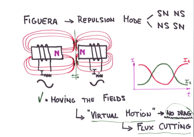
                        Hanon's Observation and Interpretations
                        I am going to show which is my interpretation. Exactly the one that you are using right now: Repulsion mode to move the fields. For more clarity:


                        BTW, the ratio of length in inducers and induced are in direct relation to the ratio of maximun to minimum current used in the electromagnets. I think it is the first time that I post this but I will keep the explanation for myself. It is easier to extrapolate it for those who have follow my posts.
                        https://figueragenerator.wordpress.com/

                        Comment


                        • Nit picking

                          This is the same things you have been posting for years. even though you had Question marks at every NN annotation, meaning you were not sure as you had not tested it.
                          it just so happens you were right with the orientation.(lucky)

                          the whole thing behind the post was driven by nip picking, poking each other with a stick. this behavior will get a team NO WHERE FAST and will only facilitate the dividing of ranks. this behavior really has to stop otherwise this thread is doomed.

                          while you have really said some off the was things in the past which had me rolling on the floor, that last sentence of your post was the most intelligent thing i have heard from your mouth in years. NOW all you have to do is back up the claim by building and testing. if your claim happened to pan out you would have aided in the advancement of the Figuera device.

                          good luck hanon in your quest to Figuera.

                          EDIT;
                          After some Severe cold and Flu tablets and a good night sleep i am thinking a little more clearer and i found i was Totally wrong about Hanon's statement.

                          See since i got that information from Doug and posted it repeatedly over the last year i find it was just a good old case of plagiarism. see since i have posted it repeatedly how in the world can it be an original Hanon research..... Well, it can't, all he did was put it in a shinny wrapper and call it his. the sad thing is this is NOT THE FIRST TIME and you should be ashamed of your self trying to claim someone else's work.

                          I'm not trying to start an argument just stating the facts as i see them.

                          These actions are disgusting, low and desperate.


                          MM
                          Last edited by marathonman; 01-08-2017, 01:58 PM.

                          Comment


                          • I challenge you to add a link to an old post with its timestamp and I will add one post of mine predating that post with the interpretation of electromagnets in repulsion mode to create flux cutting while moving the lines.

                            Even I can tell you that while researching I found a video and a page into hyiq.org which helped to relate the flux cutting concept with this device, and from a EF forum that made a post at the beginning of this thread in 2012 but he abandoned that idea. I already posted the reference to that post. Rewind and look for it. Maybe they have the merit.

                            You started with this interpretation in september 2015 when you received your instruction from someone else when you changed in a few days from a North-South with a transversed induced coil to the current interpretation. Come on...a few week ago I posted one old post from me from december 2013. Do you need that I repost that old 2013 post? I have even older posts to that.

                            My post was just to defend from the frecuent insults I receive lastly to discredit me and my interpretation. I told that my intention was to stop posting from the first days of this year, but I couldn't because of the insults I received. I can not stop posting while others keep on insulting. Maybe I should keep quiet from the 1st of january instead of commenting my impresions on the PSU values. My fault, in case I were wrong. I still do not understand that results.
                            https://figueragenerator.wordpress.com/

                            Comment


                            • Originally posted by hanon1492 View Post

                              BTW, the ratio of length in inducers and induced are in direct relation to the ratio of maximun to minimum current used in the electromagnets. I think it is the first time that I post this but I will keep the explanation for myself. It is easier to extrapolate it for those who have follow my posts.
                              Negative.

                              The amount of currents intended to be used in the Inducers, Inductors or Exciting fields is ALWAYS rated at a Minimal expense from source, otherwise it would be completely senseless to spend more in that what is expected in output at secondaries, Induced or Generating Fields.

                              Generators are based around a ten percent (10%) MAX in Watts spent at Exciters, Inducers or Inductors. And the greater the generator the lesser that percentage.

                              In absolutely ANY Generator Head you choose from wherever...the ratio will always be that the Exciters, or Inducers ROTOR FIELD are ALWAYS GREATER IN LENGTH (DIAMETER OF ROTOR IN THIS CASE) than the Induced Cores Length or DEPTH.

                              Check it out yourself.


                              Ufopolitics
                              Last edited by Ufopolitics; 01-09-2017, 02:38 PM.
                              Principles for the Development of a Complete Mind: Study the science of art. Study the art of science. Develop your senses- especially learn how to see. Realize that everything connects to everything else.― Leonardo da Vinci

                              Comment


                              • The only credit due to anyone is to Clemente. No one can take any credit of any worth after the inventor unless you can produce a reasonable improvement to the patent which would be pretty damn hard since it is the process which he patented. The design provided was just an easy example by which he could reference his explanation with visual components. Not much point in fighting over who was first, small children fight over who was first and who ate more cookies. At the end of the day no one will care and eventually everyone will forget who was the biggest ass hole. You wont even get credit for being an ass hole. Just never mention each other by name in any thread so those who seek to actually build this can.Without having to wade through all the publicly view able bull **** you two are slinging at one another. It does not make any difference who started it or who last insulted who just stop. Act your age it quit being funny a long time ago. Now you are both impeding the progress of others. First and last post here.

                                Comment

                                Working...
                                X