Announcement

Collapse
No announcement yet.

Other Lockridge theory's

Collapse
X
 
  • Filter
  • Time
  • Show
Clear All
new posts

  • Other Lockridge theory's

    This thread is to discuss Tinmanpower's theory's as related to the Lockridge device, as comments cannot be posted on the main thread by people who have not brought the related DVD.

    http://www.energeticforum.com/renewa...tml#post216918

    Regards

    John
  • #2
    A good idea, I must admit though, where we are at now is very different from Peters work although I still believe the original device had a special rotor.

    I have taken the approach that we have to work out how the individual parts worked before we can decide on the whole device. This has lead to an evolving theory.

    We are doing work on the actual motor/generator unit now and getting very interesting results. We are still using a standard armature and getting a six fold increase in voltage although at the expense of current. with a 1 to 1 ratio of motor windings to generator windings this was totally unexpected.

    Comment


    • #3
      Hi Guys,and thanks John for starting this thread.

      First off,i have to say that i dont have any theroy's on this device as yet.
      But what i do have is a device that(from what i can find on the net)sounds very similar in configuration.

      The problem i have is that every thing i can find on the net about the lockridge device either has John Bedini's or Peter Lindermann's name plastered all over it.

      So first up i must ask,is there any info on the machine other than what John and Peter have to tell us about it?

      So a little on the machine i have.
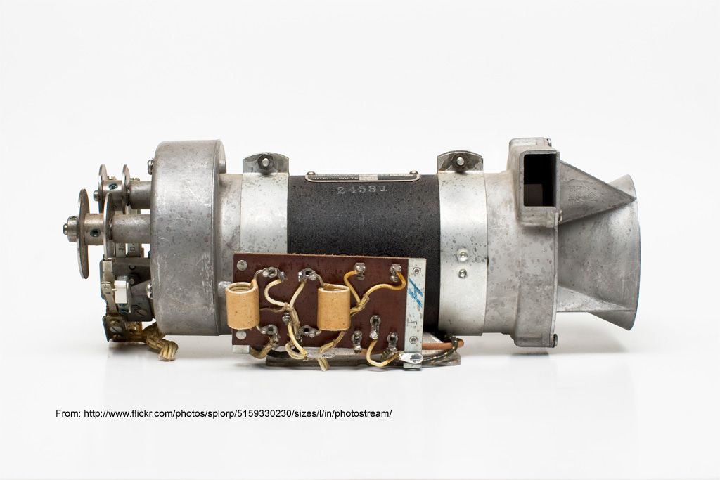
      It is from ww2 and is called a Gen-E-Motor.
      It was used to run radio truck's-there power supply for the radio equipment.

      Now the interesting thing about it is that it is an electric motor and a generator aswell,and although there may be a few of these type's of setups getting around-i have never seen one quite like this befor.

      The old 2 cylender honda civic came out with an altinator that was also a starter motor,but the one i have has a pot in which you can adjust the current output.

      So a brief description-it has 4 stator coils that are trifilar wound.
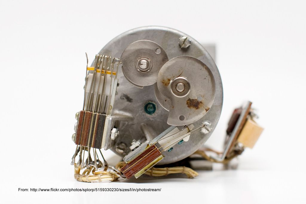
      The rotor has 49 segments in it.Now this is odd to me as i have always found that the rotor has an even division of the stator coils in an electric motor or generator.
      It has a 4 brush arrangment on the armature,two are ground and two are insulated.
      Inside the control box is a 5 ohm wire wound pot.a heavy wound wire e core inductor(that i suspect is acting as a choke) and another heavy wound round inductor that also act's as an electromagnetic switch.
      There is also another small metalic box that links the input to the first inductor to the output of the second inductor.
      I am yet to work out what this box is as the writing on it has faded to much to read.

      Now the one thing i have noticed about this machine is that the lenz force is very low.If i run the motor that it is coupled to(6hp chonda)at 1400rpm,i can turn up the pot on the generator so as it puts out 60 amps at 24 volt's.Even at this output the prime mover hardly feels it-the throtal position remains the same,and the governer dosnt move.
      I can hear a slight load being placed on the engine,but not much at all.

      But i guess what i would first like to know is-how much do you know about the lockridge device,and how you think it may work.
      Last edited by Tinmanpower; 12-03-2012, 01:07 PM.

      Comment


      • #4
        Hi Tinmanpower

        Thanks for sharing, found a couple of interesting pictures of the Gen-E-Motor. Not sure if this is the same as yours?


        Comment


        • #5
          Hi John
          That dosnt look like mine,mine looks much bigger and older.
          Im not sure how to post video's,but i will try adding the link to my gen-e-motor i have.
          This is the second video on the rebuild of the generator.
          The 1st and 3rd part are on my channel if you wish to watch them aswell.
          You may be interested in pt3 ,as it was the first run of the generator.
          I ended up extending the crank on the new engine ,and fitting the generator to that.
          Gen E motor pt2 - YouTube

          Comment


          • #6
            As i understand it,the lockridge device was very much like an old VW generator.
            Reading some of the thread on the other lockridge thread,it would seem as though it is much the same as ufopolotics ufo motor setup?

            Now i know for fact that an electric motor can be designed that can also generate power while not drawing any more current from the power input.Infact on my design,when power was drawn from the generator side of the motor-the power consumption would go down and RPM's would go up.

            I called this one the L.A.G (lenz asisted generator)
            L.A.G first part of test and explination to workings.flv - YouTube

            So this is just to show that a motor can indeed be designed to output power without raising the input consumption,and also gaining RPM's and torque.

            It is just a matter as to how you arange the coils within the motor.
            As you can see in the video,the lenz force can be manipulated to work for you -insted of against you.

            Comment


            • #7
              Hi Tinmanpower, yes that generator does look like a very good candidate for a Lockridge type device.

              Your box with the inductor and solenoid in it is a mechanical voltage regulator as far as I can tell. I believe the little silver box in it, is a capacitor and the pot is for regulating the excitement of the armature when starting the generator up.

              I am very interested in your armature, we need to establish how it is wound.

              Can you check the continuity between the segments of the armature, are they all connected together? Is there any continuity between the segments of the commutator and the iron rotor they are all mounted on (I would normally say shaft but yours does not have one). How many wires comes off each segment of the commutator? If there is more than one, do they come off in the same direction or opposite directions?

              I am trying to understand how your armature is wound, Is it Lap or Wave? If all the wires come off in the same direction it is wave. If there is no continuity between adjacent brushes you have a simple wave wound rotor.

              If there is continuity between the commutator and the ground, either you have a short or an energizer (exciter coil) in the windings.

              I believe the lockridge was simple wave wound and yours looks wave wound.

              Hi John, that looks like some sort of dynamotor with some sort of mechanical switching, possibly to rectify the output or for regulation.Very interesting.

              Comment


              • #8
                Hi mr Brown
                As much as i know how much of a bi-ch those 4 brushes were to hold out while i fitted the stator plate,and as i cant see the windings with it fitted-in the name of reserch im going to remove the stator plate so as we can have a look.
                As for the continuity test on the armature-all segments have continuity.
                They seem to be all over the place in reguards to ohm's,but i believe that may be the brushes conections that are doing that.
                So once i remove that,i will do an ohms test aswell.
                I will video this ,so as you and others can watch as i go and get a look at the windings on the rotor.

                Comment


                • #9
                  Here is what we ended up finding out about the windings on the rotor
                  Gen E motor reserch - YouTube

                  Comment


                  • #10
                    Hi, Tinman, that is a curious armature, two different sizes of wire. As you say, you cannot see under the upper layer of windings so we do not know if there are other returns and what direction they are coming from. You do have continuity between the segments which does suggest lap winding but does not eliminate wave. You did not check for continuity between the segments and earth ie an exciter winding, this could be the smaller wires. The windings in generators have very low resistance, much less than an ohm so it is difficult to measure anything although the exciters are usually higher.

                    I could be wrong about the voltage regulator and it could be something to do with the exciter if it has one but I am no expert on this.

                    The amp rating will be continuous but on peak it will generate much more but expect the thing to heat up if this is maintained.

                    So at the moment we still know nothing about this armature. I will google it to see if I can find more

                    Comment


                    • #11
                      Originally posted by Tinmanpower View Post
                      As i understand it,the lockridge device was very much like an old VW generator.
                      Reading some of the thread on the other lockridge thread,it would seem as though it is much the same as ufopolotics ufo motor setup?

                      Now i know for fact that an electric motor can be designed that can also generate power while not drawing any more current from the power input.Infact on my design,when power was drawn from the generator side of the motor-the power consumption would go down and RPM's would go up.

                      I called this one the L.A.G (lenz asisted generator)
                      L.A.G first part of test and explination to workings.flv - YouTube

                      So this is just to show that a motor can indeed be designed to output power without raising the input consumption,and also gaining RPM's and torque.

                      It is just a matter as to how you arrange the coils within the motor.
                      As you can see in the video,the lenz force can be manipulated to work for you -insted of against you.
                      UfO's motor is just an inductive switching technique to form a pulse motor that boosts the voltage for output. Although its a nifty little thing its not even to par with what a Lockridge is supposed to be. Each to his own his though... on that anyway.

                      I always pictured the thing blending the output of the motor with the generated energy at no loss. So to say it differently your motor would run a high current. The generator being (most likely) some form of high voltage low current gen, which is what Lenz Assist generators are, from my experience, are blended together either inductively or via some form of timing trick so you'll end with a true parallel of both power supplies.

                      So an example would be the motor runs on 12 volt 10 amp (120 watt) The gen outputs 220 volt at 1MA (.22 watt), under true parallel you would average the voltage and stack the amperage for an end result of 116 volt at 10.001 amp. run the power through the bulbs and end up with around 24 volt maybe 10 amp to rerun the motor.

                      I have tried several mean to do it, only one panned out and that was a spark gap. You can get a gain out of a spark gap but not a good enough gain for anything self running.

                      Just me thoughts
                      Matt

                      Comment


                      • #12
                        Originally posted by Matthew Jones View Post
                        UfO's motor is just an inductive switching technique to form a pulse motor that boosts the voltage for output. Although its a nifty little thing its not even to par with what a Lockridge is supposed to be. Each to his own his though... on that anyway.

                        I always pictured the thing blending the output of the motor with the generated energy at no loss. So to say it differently your motor would run a high current. The generator being (most likely) some form of high voltage low current gen, which is what Lenz Assist generators are, from my experience, are blended together either inductively or via some form of timing trick so you'll end with a true parallel of both power supplies.

                        So an example would be the motor runs on 12 volt 10 amp (120 watt) The gen outputs 220 volt at 1MA (.22 watt), under true parallel you would average the voltage and stack the amperage for an end result of 116 volt at 10.001 amp. run the power through the bulbs and end up with around 24 volt maybe 10 amp to rerun the motor.

                        I have tried several mean to do it, only one panned out and that was a spark gap. You can get a gain out of a spark gap but not a good enough gain for anything self running.

                        Just me thoughts
                        Matt
                        Hi Matt, The scenario you are describing is closely what we have at the moment, 20v at 40A input to the motor and 125v at 2+ or so amps on the output of the generator. Understand that this is being run with no recovery as yet and the windings have a 1 to 1 ratio so there is no step up there. There is normal generation and an inductive element from the input but this should only give us half the voltage that we have at best. It would seem that the rest is due to a huge build up of voltage in the armature.

                        The experiments we are running is to understand these inductive effects in a combined motor/generator, Our supply is half wave rectified AC at 60Hz. Significant improvements in efficiency are expected when we do start to pulse the motor due to inductive kickback, just as in PWM on a DC motor although power should go down. At that stage we can start the recovery.

                        It is interesting that you suggested such a thing when that is what we have. I am all ears.

                        Comment


                        • #13
                          Originally posted by Tinmanpower View Post
                          Here is what we ended up finding out about the windings on the rotor
                          Gen E motor reserch - YouTube
                          This PDF should help you identify which generator circuit you have although they only talk about two of the possible armature windings.

                          http://www.mhprofessional.com/downlo...6/CroftCh7.pdf

                          I am continuing to research to see what else I come up with.

                          Comment


                          • #14
                            Hi MrBrown
                            Well the little silver box got the better of me,so i removed it and set about doing diode,ohms and cap test with the DMM.
                            Looks like you were right.The only thing i could get a reading on was the cap setting on the meter.
                            It seems to be a 15 pf cap-very small in capacity,but able to handle a large amount of current by the looks.

                            I will check between armature and ground-but i dont see much sence in that,as they would be grounded by the brushes anyway?

                            Comment


                            • #15
                              Hi MrBrown
                              Great find with that PDF.
                              Ok ,from what i can make out it is a wave wound armature.
                              It states that-a wave wound armature will have two paths in parallel in the armature windings between armature terminals.

                              So im guessing that would be the two windings that are along side each other on the rotor that come from the armature.
                              What is interesting is the pic in the pdf also shows 1 large wire and one smaller one next to it-which it seems we have.

                              Now it also seems to be a shunt wound generator with rheostat.
                              But in all there descriptions,and from what i have seen-the numbers of segments in the armatures are always an even number.
                              This one of mine has 49 segment's?-i have counted them 3 times now to make sure.

                              Now 49 dosnt go into 4(number of coils)as hard as i try lol.
                              Also mine has 4 brushes,not two as depicted in all there's.
                              This may have something to do with the fact that mine is also an electric motor?

                              Comment

                              Working...
                              X