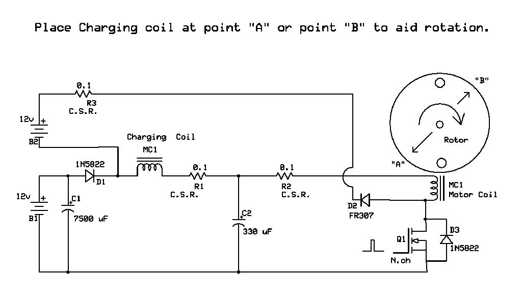
Originally posted by harctan
View Post
Announcement
Collapse
No announcement yet.
Student thesis on pulse (keppe) motor
Collapse
X
-
"Once you've come to the conclusion that what what you know already is all you need to know, then you have a degree in disinterest." - John Dobson
-
Hello ren. From what I have understood, they don't imply that the Bedini-Cole window motor has no torque. Rather they say that it wasn't designed with torque as the main focus in contrast to the keppe motor. Of course I don't know if that is true or not. Also I didn't see anywhere suggested that the window motor requires a hall sensor, although it's true that it doesn't use the SSG circuit. It's obvious to me that these three motors (and probably others) have many similarities but I personaly find the keppe design a little more straightforward and flexible. Also to my understanding the inventors have different theories about how their motors work something which I'm not really qualified to evaluate. Lastly my concern with these pulse motors is how to reroute the collapse of the magnetic field back to the motor for usable torque instead of using it to charge batteries or light lights, and to my knowledge the Newman and the window motor don't do that.
Comment
-
Hi Harctan, Here is a video clip of a pulse motor I just recently made. It uses a
resonant charging circuit to provide a capcitive discharge of a higher than
supply voltage for the drive coil, the charging coil that charges the cap to do
that is used as a second Phase, current flows through it to refill the capacitor
after the capacitor is discharged through the main driving coil so the current
in it lags the drive coil current by the pulse width and a bit more.
Pulse Motor Efficiency Comparison With Conventional Motor - YouTube
I use a photo reflector to trigger a circuit which processes the pulse into
whatever width pulse I want and feeds that to a mosfet driver chip, then the
coil is switched with mosfets. Works a treat, the motor has manual pulse
timing adjustment. In the video it is using about a 3 mS pulse.
My mosfets stay cool too.
I can supply my circuit drawings and such if you like.
Go well.
Cheers
P.S. As far as I am aware no one has ever used a resonant charging circuit in
a pulse motor like this before. So it's my invention. However it is all based
on the work of Tesla. The resonant charging circuit is patented in the "Igniter For Gas Engines Patent".
And he invented plenty of ways to secure a difference of phase in motor coils
from one phase of supply current. Just another trick for Pulse motors to use.
..Attached FilesLast edited by Farmhand; 05-02-2013, 11:47 AM.
Comment
-
Hello Farmhand. Thanks for sharing. I find your design very interesting and it looks quite efficient. The motor I'm planning on making for now will be simpler than yours, just one coil. If you have any ideas about how to use the flyback from the drive coil to get additional torque on the shaft (instead of charging a battery) in a simple and efficient way I would be very interested.
Comment
-
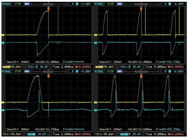
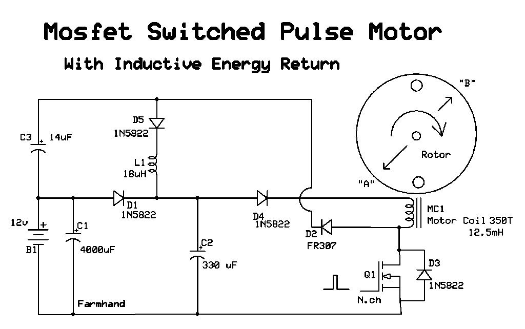
Hi Harctan, Here's some scope shots and the drawing to go with them below if they
might help. They are a comparison of when the inductive spike is "snubbed" back
to the supply or "around the coil" as is sometimes done, and as we see the
inductive energy is lost somewhere when the snubber is used. I don't have a
simple way to get the energy without the battery yet but I would say it
involves another inductor to "act" as a load and give a voltage drop it should
have as least resistance as possible I think but some inductance. Probably not
as much as the motor or charging coils have. So the solution would be a diode
and a coil and a capacitor I think.
The top two are the snubbed ones with diode connected back to the coil and
the bottom two are the way the drawing is. The pulse width remained the
same and snubbed the frequency was quite a bit lower as can be seen. My
conclusion is it's better to discharge the inductive energy into a higher voltage.
Yellow trace is the current through a 0.1 Ohm resistor (R2) and the Blue trace
is the drain of the mosfet with the scope grounds together.
Bottom left shot is a false trigger, I'll try to get a better one and fix the
picture. The pulse width is fixed at 3.16 mS and I do not change it.
Oh please note that I had to change the volts per division for the blue trace
in the bottom shots from 10 to 20 to fit it in.
My discharge voltage and current wave forms fit together like hand in glove,
the peak power looks good for the 2.8 Watts input when the shots were made.
Main Circuit.
Shots.
Cheers
Comment
-
I have to agree with Ren. The "analysis" of Bedini's technologies are wildly conflated. The SSG and the Window Motor are two completely different beasts.
For the SSG, Bedini claims "no torque" (but does point out that there is some torque). The SSG just produces spikes which refurbish batteries.
The window motor produces torque.
Two completely different animals.
It worries me that the youtube you posted might be dis-info - the authors should know better than to conflate these two technologies
The use of fans, and pieces of paper are scientifically non-rigorous.
You sound like a smart, open-minded person. Build a dynamometer (look for Lindemann's "Electric Motor Secrets").
The circuit you posted looks very similar to the so-called "Bedini-Cole" circuit.
I didn't understand this circuit until I followed the "rules" posted by Bedini.
A battery cannot supply current and charge itself at the same time.
I tried to design such a circuit and came up with something similar to the Bedini-Cole circuit. Snip both ends of the coil with transistors and focus the back-spike into the (disconnected, not current-supplying) battery using diodes.
Converting a huge (voltage) back-spike into usable current (work (?)) is an interesting question.
Bedini is telling us the the converter is a battery. I don't (yet) have an answer to how you might do that without a battery.
I really like your initiative in scientifically researching theses designs.
What you are doing is important work.
I was schooled in EE, 30-ish years ago (but not currently active). If there is anything I can do to help your research, please ask.
ptLast edited by pault; 05-05-2013, 02:55 AM.
Comment
-
Originally posted by pault View PostI have to agree with Ren. The "analysis" of Bedini's technologies are wildly conflated. The SSG and the Window Motor are two completely different beasts.
For the SSG, Bedini claims "no torque" (but does point out that there is some torque). The SSG just produces spikes which refurbish batteries.
The window motor produces torque.
Two completely different animals.
It worries me that the youtube you posted might be dis-info - the authors should know better than to conflate these two technologies
The use of fans, and pieces of paper are scientifically non-rigorous.
You sound like a smart, open-minded person. Build a dynamometer (look for Lindemann's "Electric Motor Secrets").
The circuit you posted looks very similar to the so-called "Bedini-Cole" circuit.
I didn't understand this circuit until I followed the "rules" posted by Bedini.
A battery cannot supply current and charge itself at the same time.
I tried to design such a circuit and came up with something similar to the Bedini-Cole circuit. Snip both ends of the coil with transistors and focus the back-spike into the (disconnected, not current-supplying) battery using diodes.
Converting a huge (voltage) back-spike into usable current (work (?)) is an interesting question.
Bedini is telling us the the converter is a battery. I don't (yet) have an answer to how you might do that without a battery.
I really like your initiative in scientifically researching theses designs.
What you are doing is important work.
I was schooled in EE, 30-ish years ago (but not currently active). If there is anything I can do to help your research, please ask.
pt
make several claims I'm sure are an exaggeration.
I don't think Harctan is promoting them though, I think it was just to show the
type of motor he is working with.
As for my test with a piece of paper, that was in order to show other
experimenters. If you think any of my video's look like disinfo feel free to point
out which one and why, if I see reason that might be true I'll make the video
unlisted, simple.
I'm not sure anyone is wanting to recharge any battery they are using here, if
a motor was using 10 watts and recovering 2 Watts to a charge battery there
would hardly be any point for the charge battery, so it might make sense to
recycle that 2 Watts back through the motor which does not necessarily
mean even putting it through the drive battery, the recovered energy could
be fed to a capacitor then put back through the motor to improve efficiency
over having no charge battery and the spike snubbed and lost.
It's a simple concept, send the spike to a capacitor then dump it through the
motor coils or coil to aid in the rotation.
You are absolutely correct when you say you cannot charge a battery
drawing 10 watts with less than that returned. But if a battery is using
2 watts and 10 watts is applied to it it will charge just fine. As is proven by
solar systems. The 2 Watts run energy comes directly from the 10 Watts
applied so that the battery only gets 8 Watts through it. As soon as the input
to the battery becomes more than the output from the battery the battery
just takes the difference. If the return current is out of phase then it needs
to be phase shifted so that it goes directly to the motor and not to the
battery then the motor like the Watson Machine does because that is no good
for the batteries.
As you can see in my drawing the return is bypassing by the supply battery
so that the supply battery only gives and does not take. Any return energy
without a charge battery should take a similar path (NOT) through the battery.
Comparisons with fans are dubious if the demonstrator has an agenda to make
money or gain video hit's. For example I could have changed the pitch on the
purchased fans blades or introduced extra drag on the purchased motor to
give an advantage to myself. AS it turns out I was unable to compare to a
16 Watt fan because it moved way to much air too efficiently for me to beat.
Induction motors can be very efficient if they are loaded correctly and PFC.
Often purchased fans don't even have "ball" bearings, just bushings which
have a lot of drag. Take a conventional fan install ball bearings and it will be
more efficient. The design of the bushings is such that they are designed to
go dry then heat up and slow down then fail, so a new one is purchased. The
rear bushing is usually the one which gets dry and hot, after some time the
blade no longer spins freely, that's when it's time to oil the bearing (bushing)
by pulling the fan apart to get at the rear bushing.
Cheap purchased fans are designed to fail, but before they do they get very
inefficient for quite some time. Which could be a bigger expense than the cost
of the fan itself in my opinion.
If one of my purchased fans does not spin freely I fix it or scrap it.
CheersLast edited by Farmhand; 05-06-2013, 06:03 AM.
Comment
-
This works for me to return the inductive energy released from the motor coil to the capacitor C2 to be reused by the motor coil.
How it works is the spike charges the capacitor C3 briefly because of the
inductance/impedance of the coil L1, C3 has the least impedance I think ( capacitors in parallel will help lower the cap impedance),
then after C3 is charged the inductor L1 discharges C3 into C2 to be reused.
In my setup the inductive spike charges C3 to about 25 volts for about 400 microseconds
before C3 discharges through L1.
D4 is a blocking diode so that the rotor magnets don't try to charge C2.
Doing this has greatly improved my motor I can run it from 300 mA at 1900 rpm
right up to 1.7 amps Amps for 3500 rpm, my mosfets don't have heat sinks
and stay cool at 300 mA input they feel cold.
The motor starts easier and runs faster for less input and with a shorter pulse width. I'm stoked, now to the generator setup.
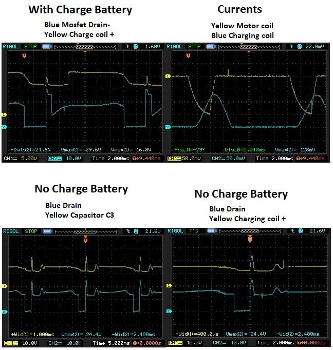
I can make a scope shot showing the energy being captured and reused if you want. The answer is always a coil a capacitor a diode or all three
Hope this helps.
P.S. Here are the wave forms anyway. The beauty of it is that it can still
charge a battery if you want by connecting the battery in series with the
inductive energy return. Although the performance while charging a battery is
less of course.
CheersLast edited by Farmhand; 05-05-2013, 09:21 PM.
Comment
-
FH, my comments were not directed at your youtube. If my wording made it seem otherwise, then I apologize.
Edit: Until a few minutes ago, I was sure that the Keppe video contained pieces of paper on the fans. I was wrong. I retract the comment about the paper, I was focused on the Keppe video, but confused myself about what I saw in which video. My real point is about the use of a dynamometer, in a full-blown analysis.
FH, sorry. I do find your design interesting and am re-reading your last few posts about it...Last edited by pault; 05-06-2013, 12:39 AM.
Comment
-
@ pault:
The claims about the keppe motor that I have written and linked above belong to the keppe motor group and are not my own. For me it's just a fun project that will also serve as my thesis so it's win-win. I don't really expect to get any high efficiency from this. And yes I do plan to use a proper dynamometer setup to measure it. My progress has been slow so far because I'm having a piece of the rotor machined and I'm still waiting.
@ Farmhand:
Thank you very much for sharing your designs. They look very interesting and may prove useful to my project (or a future one). I will have to study them more closely though since I'm a novice in electronics (and most everything else for that matter).
Comment
-
Originally posted by harctan View Post@ pault:
The claims about the keppe motor that I have written and linked above belong to the keppe motor group and are not my own. For me it's just a fun project that will also serve as my thesis so it's win-win. I don't really expect to get any high efficiency from this. And yes I do plan to use a proper dynamometer setup to measure it. My progress has been slow so far because I'm having a piece of the rotor machined and I'm still waiting.
My mistake, 30 years ago, was to believe that what "they" were teaching me was confirmed fact. New discoveries would be built upon these confirmed facts.
I, now, see that that's not the case. What is taught is what is believed to be true, but not 100% confirmed fact.
So, experiments like yours might reveal something new.
If, OTOH, your experiments don't reveal something new, they will still give you a "hands on" gut-feel (experience) for what's going on. That is what will propel you into understanding these issues and make headway.
Just don't BS.
Observe.
Explain what you see truthfully.
(Please) Tell us what you learn.
Ask us for help, if there is any way we can help you. There's a lot of talent and knowledge on this group that you've decided to join... (and we're willing to share)...
pt
Comment
-
Originally posted by pault View PostI have to agree with Ren. The "analysis" of Bedini's technologies are wildly conflated. The SSG and the Window Motor are two completely different beasts.
For the SSG, Bedini claims "no torque" (but does point out that there is some torque). The SSG just produces spikes which refurbish batteries.
The window motor produces torque.
Two completely different animals.
It worries me that the youtube you posted might be dis-info - the authors should know better than to conflate these two technologies
The use of fans, and pieces of paper are scientifically non-rigorous.
You sound like a smart, open-minded person. Build a dynamometer (look for Lindemann's "Electric Motor Secrets").
The circuit you posted looks very similar to the so-called "Bedini-Cole" circuit.
I didn't understand this circuit until I followed the "rules" posted by Bedini.
A battery cannot supply current and charge itself at the same time.
I tried to design such a circuit and came up with something similar to the Bedini-Cole circuit. Snip both ends of the coil with transistors and focus the back-spike into the (disconnected, not current-supplying) battery using diodes.
Converting a huge (voltage) back-spike into usable current (work (?)) is an interesting question.
Bedini is telling us the the converter is a battery. I don't (yet) have an answer to how you might do that without a battery.
I really like your initiative in scientifically researching theses designs.
What you are doing is important work.
I was schooled in EE, 30-ish years ago (but not currently active). If there is anything I can do to help your research, please ask.
pt
In regards to converting the inductive discharge into useable current without the battery, the best answer, and the one Farmhand seems to be exploring, is the capacitor. The beauty of the inductive discharge in the SSG arrangement is its ability to charge a capacitor to a much higher voltage than the initial input. Watch a short simple video I made here about capacitive discharge.
Capacitive discharge - YouTube
Now imagine that coil was part of the stator, and its energy discharged into the rotor at the correct time. FYI, a 12v discharge through that coil barely makes the magnet move.
Regards"Once you've come to the conclusion that what what you know already is all you need to know, then you have a degree in disinterest." - John Dobson
Comment
-
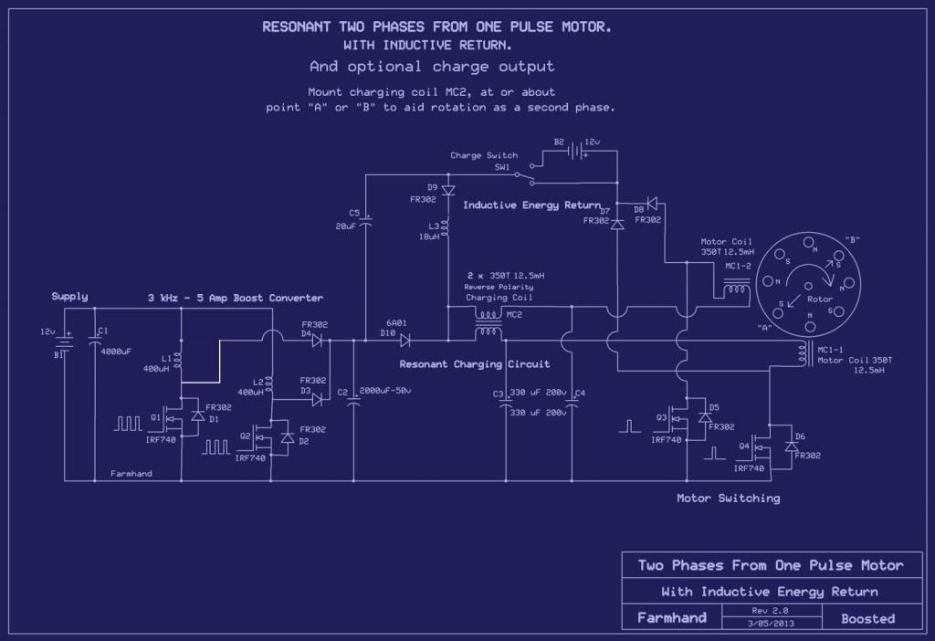
Exactly Ren, The setup I have now is as the drawing below, my schematic
drawing software won't allow me to draw coils at different degree angles so I
just left the charging coil from the resonant charging circuit back in the
positive line in the drawing, but it goes at the rotor like the motor coils.
The inductive energy released goes to the return capacitor (C5) in series with
the supply, which can be either the Supply as in (in series with the battery
with a regular pulse motor), or the boost capacitor (C2),that allows the
inductive spike to charge the return capacitor quickly then dump through the
small inductor (L1) back to the other side of the diode for the motor to reuse,
(D9) prevents reverse flow. Alternatively a charge battery can be put in
series with the return circuit as well which does change the performance of
the motor, the charge battery seems to make the motor spin freely at a
faster rate but less able to take loads in my setup at least.
I like the idea of having the best of both worlds.
This is my latest drawing showing a dual main coil setup with a bifilar charging
coil to feed their capacitors, the charging coil also aids the rotor and is
positioned to account for the delay in it's currents phase as compared to the
motor coils current, the charging coils currents are after the motor coil
currents, that makes two driving phases from one switching event.
My circuit uses a boost converter to pre-boost the voltage, then the charging
coil also causes an increased voltage for the motor coils.
As far as I know this is a new design in two ways, and I claim them as my
inventions which are free for all to use. Enjoy.
The drawing shows a motor designed to withstand 100 volt pressures at the
mosfet drain but with some higher voltage rated diodes and capacitors it
could be easily upgraded to handle up to 400 volts at the mosfet drain.
The currents through the motor coils and the charging coil reinforce each
other in two ways 1, through the coil discharges and 2,through the effects of
the magnet passings.
The charging coil should be placed in a position lagging in phase to the motor coils to
best aid the rotor, this can be found experimentally or calculated using some
known variables. The amount of the lag in phase is dependent on a few
factors that should be obvious to those skilled in the arts.
Pulse Motor - More Proper Wave Form - YouTube
Just to reiterate the return capacitor (C5) is in series with the supply (whatever it is) and dumps over a diode.
CheersLast edited by Farmhand; 05-20-2013, 01:06 PM.
Comment
-
Hey, thanks for your all your responses.
This past weekend was my first chance to revisit FH's circuit (the 2nd one posted). (Haven't gotten around to thinking about this 3rd circuit FH has posted, but I will).
It is quite clever.
FH (2nd circuit) uses a tank circuit - a coil (L1) in parallel with a capacitor C3) - to capture the back spike.
The cap (C3) slurps up the back-spike, the coil (L1) resists any instantaneous change.
Then, the cap (C3) "slowly" discharges through the coil (l1), which feeds the charge to another cap (C2) which is in parallel with drive battery.
The diode setup makes this a one-way affair, the charge flows from C3 to C2 through L1.
The next time that the motor coil (MC1) is energized, the energy comes from the parallel combination of B1 and C2, which takes some of the load off of B1.
Here are some random thoughts / questions about this circuit (#2, I haven't grokked #3 yet):
- What happens if the generator coil is turned 90 degrees and moved closer to the axle? I.E. the gen coil points at the face of the wheel (instead of at the outer edge of the wheel) and the gen magnets moved as close as is reasonable to the axis of the rotor? I would think that the motor coil is generating a flywheel effect, and the generator coil(s) should remove as little of the flywheel momentum as possible...
- This circuit (#2) looks like it should also apply to the SSG? Yes? Is there any benefit?
- Ckt #2 shows a pulse on the gate of Q1. What is generating this pulse?
- The back-spike from MC1 is only half-rectified. When I've seen spikes, I've also seen over-shoot and under-shoot. Would a full-wave rectification scheme not collect every last drib of energy?
- L1 is a coil. Is it possible to arrange it so that L1 functions as L1 in the tank circuit (during magnetic collapse of MC1) - and - be the recovery coil, in different phases of operation of the circuit?
- The motor coil is a coil. When it is driven, it motors the rotor. Since it is driven by a short pulse, most of the time it is "off". Can that same coil also be the "recovery" coil? E.G. put "A" and "B" behind in phase? E.G. MC1 fires, then generates. Or the opposite - MC1 generates, then drives.
- Tuning. A tank circuit favors a certain frequency (aka pulse width). Did you consciously pick a tuning for this tank circuit? If so, what did you base this decision on?
Comment
-
thinking out loud
Trying to simplify my questions...
Imagine a single-coil driving a Bedini SSG wheel with, say, 16 magnets.
There are 3 things (maybe 4) that a coil can do:
1. The coil is powered, and produces a magnetic field. The field attracts an incoming magnet and imparts torque on the wheel.
2. The coil is suddenly switched off and produces a sharp spike. The spike can be harvested.
3. The coil can sit "idle" while 7 magnets pass over it. The coil generates. This generation can be harvested.
Is it possible to tune the system so that (2) and (3) pay for (1)?
Repeat for the next 8 magnet passes.
(4. The coil is suddenly turned on. It produces a negative sharp spike that opposes the sudden incoming positive potential. Can this effect be harvested in some way? Or counteracted?).Last edited by pault; 05-25-2013, 12:37 AM.
Comment
Comment