Announcement

Collapse
No announcement yet.

Student thesis on pulse (keppe) motor

Collapse
X
 
  • Filter
  • Time
  • Show
Clear All
new posts

  • #46
    These are the circuits I use.

    I stuck some tar foil strips to the rotor and put an rpr-220 photo-reflector on
    an arm that swings in a small arc for timing adjustment.

    Optical Senor module
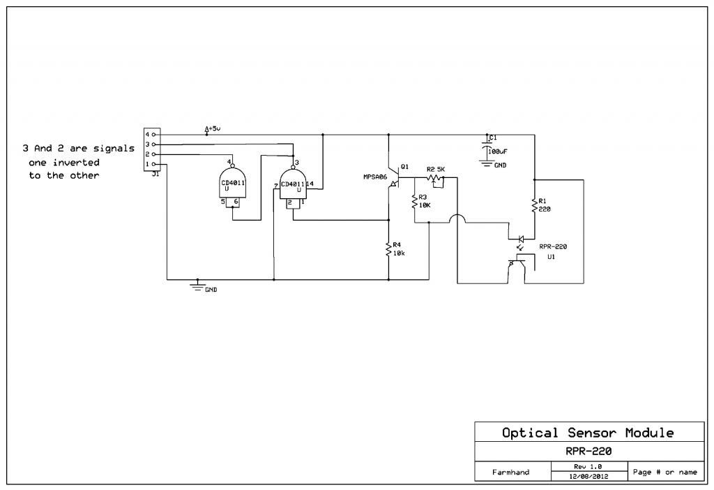

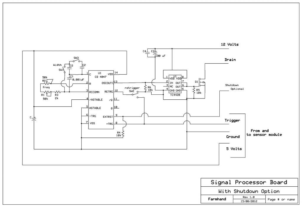
    Then the squared signal from the sensor module is sent to the signal
    processing board, which uses a CD4047 to process the signal to the desired
    width.


    ..

    However I don't use bipolar transistors much as switches, I use mosfets for
    switches, and mosfet drivers to drive them with, the pull down resistors are mainly
    2 k to 10 k usually 10 kOhms. Usually a 100 uf capacitor to ensure the mosfet
    driver can get enough juice quick and a smaller one in parallel with it for good
    measure. I use 5 volt signal to the chip but the chip drives the mosfet with 12 volts,
    but it could drive the NPN with 5 volts maybe....

    I think a driver chip would drive a bipolar transistor. But I'm not sure how it
    well it would work.

    I'm using two IRF740 in parallel and they barely get warm passing 4 or 5 Amps.

    The faster turn off will give the better spikes for sure.

    I also use a picaxe to control a boost converter to adjust the supply voltage so
    the 5 volts for me is already there to use.

    Using Ohms law if 12 volts is applied to the base of the NPN,

    then 12v /10 000 Ohms = 1.2 mA
    and 12/ 2000 Ohms = 6 mA

    not much.
    Last edited by Farmhand; 08-15-2013, 07:32 PM.

    Comment


    • #47
      Hello Farmhand, thank you for your input. Unfortunately your method is a little too complicated for me right now. If you have any ideas as to how I can achieve a faster turn off so I can get the flyback spike back in the circuit I'm using (as seen in my second post) I'd be happy to try it. I don't have much expierence with mosfets yet. Is there any advantage in using them over bipolar transistors?

      Comment


      • #48
        Hi Farmhand, I like the use of 4011 to square up the pulse on your optical moduel, If you used 12V & changed the value of R1 it looks like the 4011 will directly drive his bi-polar tansistors," note extra gates " I say this as I use similar chip 4013 @ 12V to drive transistors @ 1 MHZ in an isolation inverter.
        PS I use that isolation inverter to drive Fets in Bi-polar Pwr supply,
        for motor control.
        Peter

        Comment


        • #49
          Thanks to your suggestions above I managed to pair the optical switch with the PWM from here: DIY Homemade Signal Generator with Pulse Width Modulation - RMCybernetics .This gave better results with the flyback collection and recirculation plus it provides speed control for the motor. You can see a demostration here: Keppe pulse motor with improved circuit under load - YouTube .I used my phone to film this so the quality isn't great. In the video I have a switch so I can demonstrate the effects of the recirculation of the flyback from the coil. As you can see with the recirculation the speed increases from 1825rpm to 1960rpm while the amp draw decreases from about 109mA to 102mA. The left (black) multimeter shows input voltage (Volts) and the right one (yellow) shows input current (mA). The values of the components are as follows: V1=23V, C1=220uF @ 100V, L1= 900 turns of 0.75mm (~AWG#21) @ ~9 Ohms, T1=TIP42C, T2=MJE13009, T3=TIP41C, R1=470 Ohms, R2=R3=1000 Ohms, d1=d2=d3=1N4007, Q1=H22A1.

          Comment


          • #50
            Originally posted by harctan View Post
            Hello Farmhand, thank you for your input. Unfortunately your method is a little too complicated for me right now. If you have any ideas as to how I can achieve a faster turn off so I can get the flyback spike back in the circuit I'm using (as seen in my second post) I'd be happy to try it. I don't have much expierence with mosfets yet. Is there any advantage in using them over bipolar transistors?
            Yes there is a simple trick which is the first method I used to drive a mosfet and
            it should turn off the bipolar as well, I think it may need a mod and I can get
            some outside advice on that.

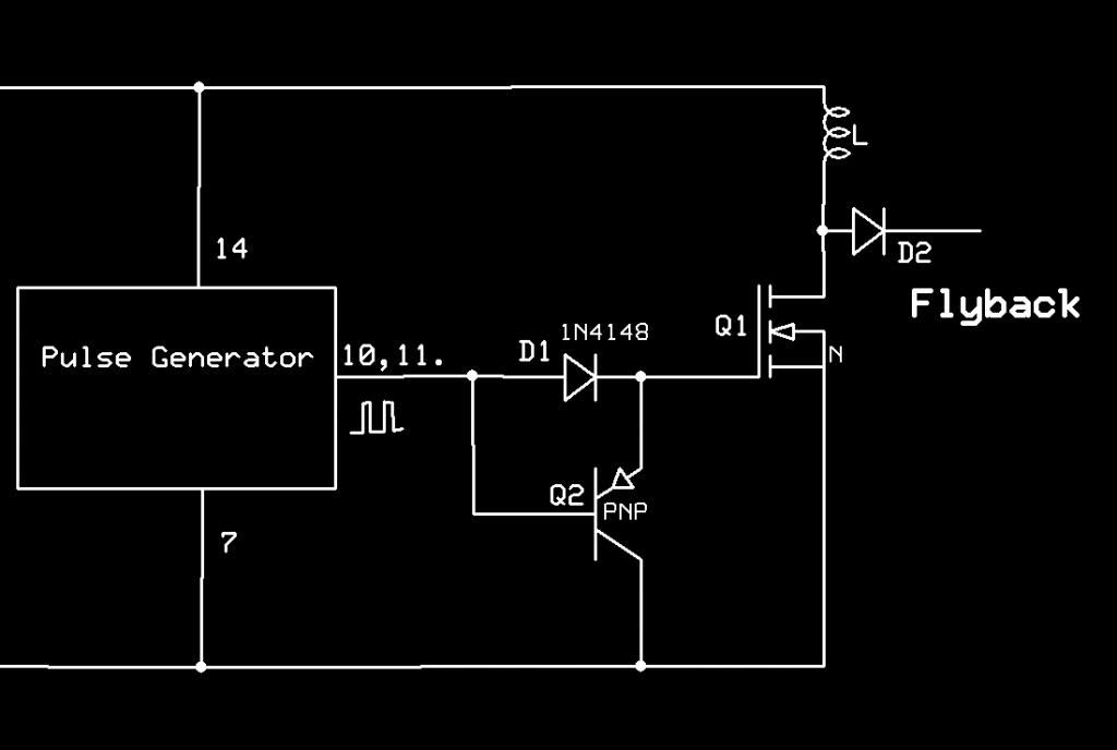
            The way is to use a pnp transistor and a signal diode, I'll make a quick schematic
            and Edit it in here very shortly. Please bear with me.

            Here it is. The way it works is that the signal holds the pnp "off" when the
            signal is high which isolates the gate/base from circuit ground, then when
            the signal goes low the pnp is driven "on" which ties the gate/base to circuit ground,
            if that will work with a bi polar I am not sure as yet, I don't use them as switches,
            but I will ask. I'll get back on that.

            Ummm, getting the pins on a TO92 transistor correct can be confusing for me, I recommend
            using the data sheet and make sure the pins are correct. emitter to ground, collector to the gate/base.
            I think I still have a circuit that uses that arrangement, it works well with mosfets at modest frequencies.

            Obviously the Mosfet Q1 is the switch, and Q2 is the PNP turn off transistor, I use small TO92 PNP transistor like a MPSA05 and the diode I use 1N4148.


            ..

            P.S. Mosfets have a much lower "on" resistance and make probably the best "switches" for quick on and off action,
            but they do allow reverse currents through the body diode, which might be undesirable for a motor
            of certain designs. There are logic level mosfets as well which require only 5 volts to turn on all the way or full on
            which is how to get the lowest "on" resistance. To prevent waste heat the switch should turn on and off as quickly
            as possible or "Chop" and the flyback clamped to about double the supply voltage somehow. A square digital signal
            with enough power and a turn of mechanism chop the turn off quick produces the best flyback. As we know it is
            the rate of change that does the trick. I now use mosfet driver chips which really drive the mosfet on and off proper fast,
            I use TC4420 for multiple mosfets or HF, TC4427 and TC4428 as well. I also have some good High side low side drivers for
            a future Tesla Coil project. I just like them a lot for on off switches.

            Cleaning up a signal with a schmitt trigger or a logic gate is fairly easy a
            CD4001 chip has four gates, they can be used in parallel to increase current
            capability and they can drive a mosfet no problem at modest frequencies,
            Logic chips also make awesome oscillators. I have one that will produce stable
            signals up to 3 or 5 Mhz, can't remember exactly but it's fast. They cost
            about 45 cents each. THe operation of a logic gate is actually quite simple
            but it is a bit obscure at first to those of us not formerly trained.
            A good book is "The CMOS Cookbook" by Don Lancaster, awesome reference
            and learning book.

            ..
            Last edited by Farmhand; 09-09-2013, 07:52 AM.

            Comment


            • #51
              A Document for you

              Hi Harctan, I've received advice that the method above won't work.

              However I have also been given a document to study.

              Download this.
              https://skydrive.live.com/?cid=32a91...53&app=WordPdf

              The entire document is good but a bit complicated.

              There is a test circuit at figure 5 to determine the capacitor value for your transistor.

              However at the end in Appendix C there are some graphs with curves for
              some capacitor values for some different transistors, depending on what type
              of transistor you have might mean you need to experiment.

              I would try 10 nF across the drive resistor. Have you tried that yet ?

              Cheers

              Comment


              • #52
                Originally posted by Farmhand View Post
                Hi Harctan, I've received advice that the method above won't work.

                However I have also been given a document to study.

                Download this.
                https://skydrive.live.com/?cid=32a91...53&app=WordPdf

                The entire document is good but a bit complicated.

                There is a test circuit at figure 5 to determine the capacitor value for your transistor.

                However at the end in Appendix C there are some graphs with curves for
                some capacitor values for some different transistors, depending on what type
                of transistor you have might mean you need to experiment.

                I would try 10 nF across the drive resistor. Have you tried that yet ?

                Cheers
                Hello Farmhand, thanks for the feedback. The link that you gave me doesn't seem to lead me to any documents. It looks like it's empty.

                Comment


                • #53
                  I set up a small prony brake and have the first results. At 36V and 11W of input I measured efficiency of ~50%. Although the readings from my instruments are probably not very high in accuracy, I believe that for my purposes it's within a logical margin of error. I also tested it at lower voltage (23V) but the efficiency droped a lot at ~30%. I plan on doing more tests and will post the results here in more detail and maybe also a video.

                  Comment


                  • #54
                    Here is a video with the test setup and the calculations: Efficiency measurement of keppe pulse motor - YouTube. The results from this test are consistent with my other tests and show an efficiency of around 50%. The measurements were taken with the motor still cold. As you can see from the video the speed was still increasing while the amp draw was going down. That is because I prefer not to run the motor for long for safety reasons. For comparison's sake the motor from the Keppe motor group (which my motor is based from) is calculated by them to have an efficiency of 70% (Keppe Motor :: The Energy of Life ::) which is achieved at higher voltages. If you find any errors in my methodology or calculations let me know.

                    Comment


                    • #55
                      I made a video with the final results, test procedure, measurements and calculations for anyone interested: Final results on keppe pulse motor project - YouTube

                      Comment


                      • #56
                        Originally posted by harctan View Post
                        I made a video with the final results, test procedure, measurements and calculations for anyone interested: Final results on keppe pulse motor project - YouTube
                        That was nice presentation for sure. You might consider converting that rig to a Newman Motor. Probably rock and roll.

                        Cheers
                        matt
                        Last edited by Matthew Jones; 01-13-2014, 08:17 PM.

                        Comment


                        • #57
                          Well and nicely done. My congratulations.

                          Comment


                          • #58
                            Thank you both for your comments, I'm glad you enjoyed the video. I'm not sure how I would go about converting it to a Newman motor. It is my understanding that the high efficiency claimed by Newman is dependent on the large size of his motor.

                            Comment


                            • #59
                              That may be the case. The one I built years ago had number 28 wire and ran real fast. I don't recall all the details but I know that sucker was running 4-5k rpms with just tiny bit of current. It looked about the same you motor thats why I mentioned it.

                              Cheers
                              Matt

                              Comment


                              • #60
                                Hello Matt, the geometry of both the Newman and the Keppe are pretty much identical, as far as I can tell. One major difference is the size as we mentioned above. Also the Newman motor uses brushes and commutator. Did you use brushes for your motor or was it curcuit driven? Any other details you remember?

                                Comment

                                Working...
                                X