Announcement

Collapse
No announcement yet.

Inductance Equation

Collapse
X
 
  • Filter
  • Time
  • Show
Clear All
new posts

  • Inductance Equation

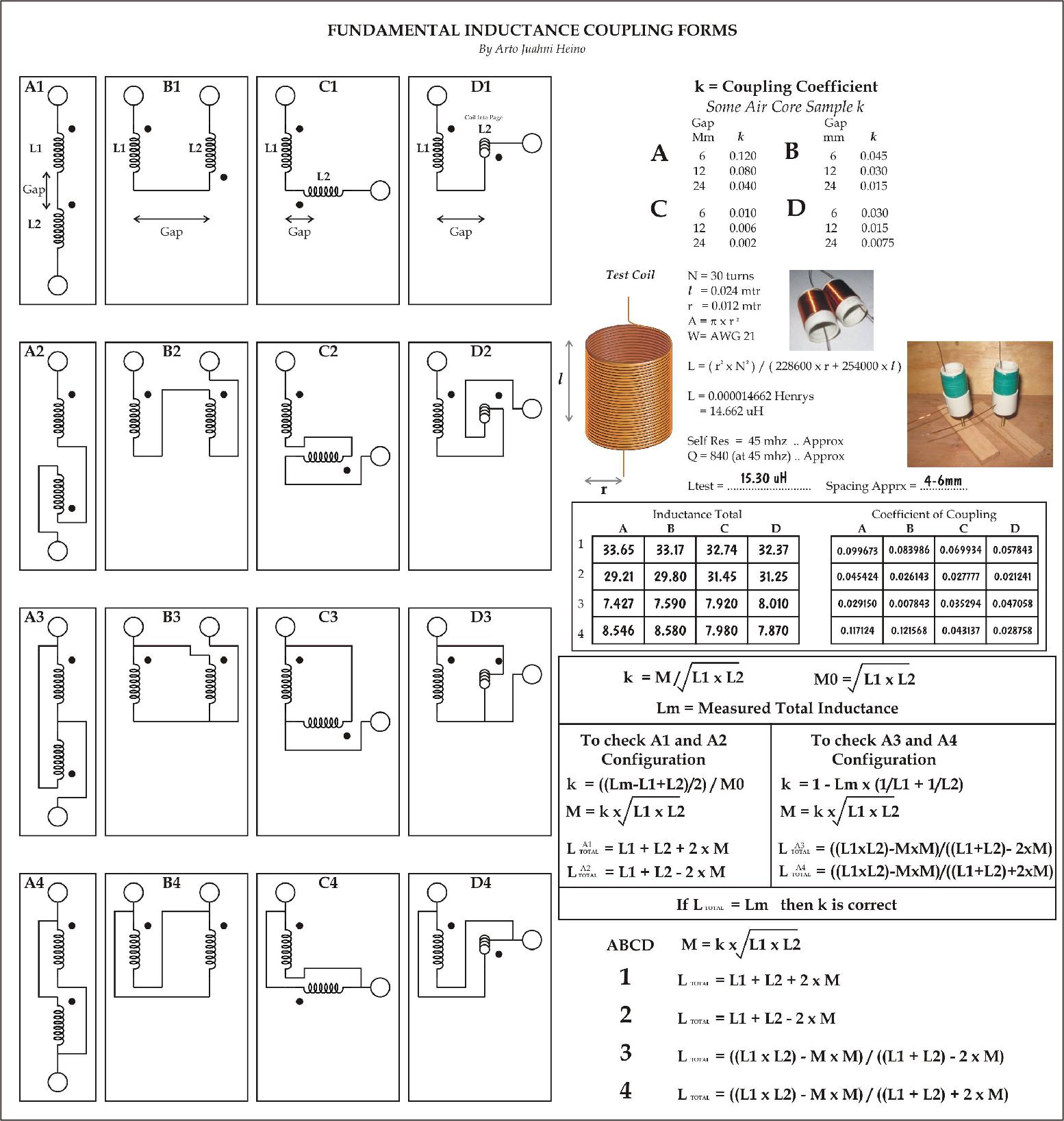
    Hi All, I know there are a lot of great engineers and maths people who read this forum, I have a Mutual Inductance chart that I am trying to finish.
    I am sure I have missed some simple maths solutions here, please help, I am wasting too much paper scribbling to solve this.

    Lt = ((L1xL2)-M^2)/((L1+L2)-Mx2)

    I figured this out

    Lt = M + 1/(1/(L1-M) + 1/(L2-M))

    Then this is far as I have gotten

    1/(Lt-M) = 1/(L1-M) + 1/(L2-M)

    What I am trying to get a result is

    M = *********

    If somebody recognizes these type of equations or know
    how to solve this, I would very much appreciate some help.

    Regards Arto

  • #2
    I'm not sure of your mathematics background, electrodynamics requires familiarity with calculus. Inductance gets very complicated, it's a scalar that requires cross multiplication and integration.

    what's the application? if it's a transformer then most of all the equations have been somewhat sorted over the yrs already, only once you start digging into them it becomes apparent how complex it is and the reasons for 'close enough'. heck there is no A-B path set of equations, you kinda start in the middle and constantly re-adjust.

    here's a link to a good start on mutual inductance.
    Mutual Inductance

    Comment


    • #3
      Hi Madhatter, No problems with electrodynamics, just need help with cross products and simultaneous equations and differential equations, I have volumes of equations on EM, I am completing a chapter on inductance and I have references dating to 1890's.
      I worked out the Coupling co-effient on the series circuit OK

      M = k x sqrt(L1xL2)

      k = M / sqrt(L1xL2)

      Lm = measured inductance

      therefore

      k = ((Lm-L1+L2)/2)/sqrt(L1xL2)

      Lt = L1+L2+2xM (Total inductance)

      If Lt = Lm then k is the correct coefficant of coupling

      The Parrallel circuit is a little harder which is the one I am asking for a little leg up, if not I will work it out on my own like I have with all my other equations.

      Regards Arto

      Comment


      • #4
        My Basic Coupling Sheet

        Here is what I am working on, it is very useful for working out your coil layouts and help you workout your resonant circuits planning. You will find the C and D layouts are those used by Tesla in all his small resonators. Regards Arto
        (This sheet is not finished yet)

        Comment


        • #5
          Arto, read thru this link, Numerical Methods for Inductance Calculation

          It really requires a knowledge in calculus and trig along with understanding 3d matrix for the scalar component. Matrix calculus - Wikipedia, the free encyclopedia

          A lot of the leg work has been done in the past, a good reference is the radio engineers book.

          If the goal is to design a coil for a specific application, well that requires the above and matlab, mathematica or other software specializing in compiling multivariable calculus will help speed it up.

          If I've miss-understood your post let me know.

          The mutual inductance equation takes into account the permitivity of free space as a scalar that is integrated over the area of the coil. Robert Weaver put together a very good program and paper on the inductance of a helix of any pitch about a decade ago. His paper is linked at the end of the above posted link.

          Comment


          • #6
            Hi Madhatter, I am sorry you do not understand what I am asking, I do not need any information on inductance calculations, like I have said I have references and volumes that date back to Maxwell. As you can see, this is a chart to help you with the coupling coefficient, your work is to get 2 pieces of information, 1, the Inductance measured from a Inductance meter of each coil and both coils together 2, measure the spacing between the coil, then you can calculate the coupling coefficient which is crucial for resonating coils. The Test coil is to compare the measurements to the calculation and derive the coupling coefficient. The whole object is to layout your coils so you know how they interact and cause changes to the resonant frequency of the system. The calculation of the test coil is arbitrary so I chose the wheeler formula as an example only.
            This chart is for empirical evidence only so you can chart the coefficient with the spacing, such as I have done at the top of the chart.
            It has occurred to me that most of the experimenters do not use much math, so I hope this chart will help those who can shorten the many hours spent in moving and adjusting coils for optimum performance. I hope this makes it clear, please do not post if you cannot help with the math, I will post my solution, Regards Arto

            Comment


            • #7
              Thanks for the clarification.
              As requested I'll not post again.
              This page may help you: Coupling Between Coils

              Comment


              • #8
                Found Solution- Simple

                No problems Madhatter, I just needed a little more time to find the simple answer. Regards Arto

                I made this just for all the experimenters in this forum. I hope you find it of value. It is also useful to find the voltage attributes when the coupling coefficient is defined:

                V2 = V1 x k x N2/N1 ( V = volts, N = turns)

                V2 = V1 x k x sqrt(L2/L1)

                Comment


                • #9
                  Tested and All OK

                  I tested 2 coils with my inductance meter and used these equations to get the Coupling Coefficient. The results were very good and very accurate.This page is almost completed, now for the next 100 pages. Regards Arto

                  Comment

                  Working...
                  X