 Tweet
Tweet
Originally posted by Mad Scientist
View Post
You seem very experienced with the idea of perpetual motion, therefore I cannot be explaining myself very well through my writings, illustrations and videos because I don't feel like we are on the same page yet.
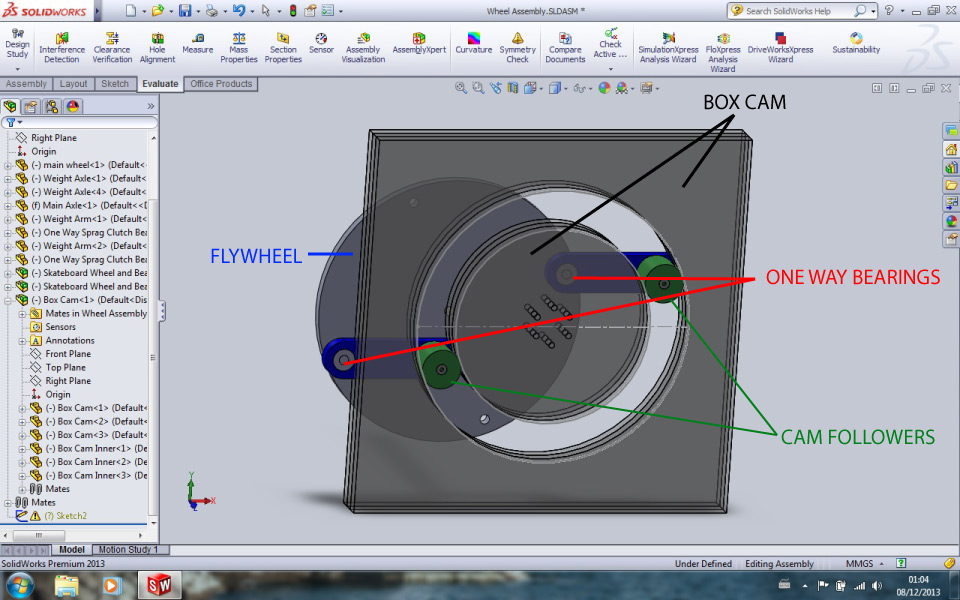
If you watch the 1st 5 seconds of the video, you can clearly see the arms have one way bearings.
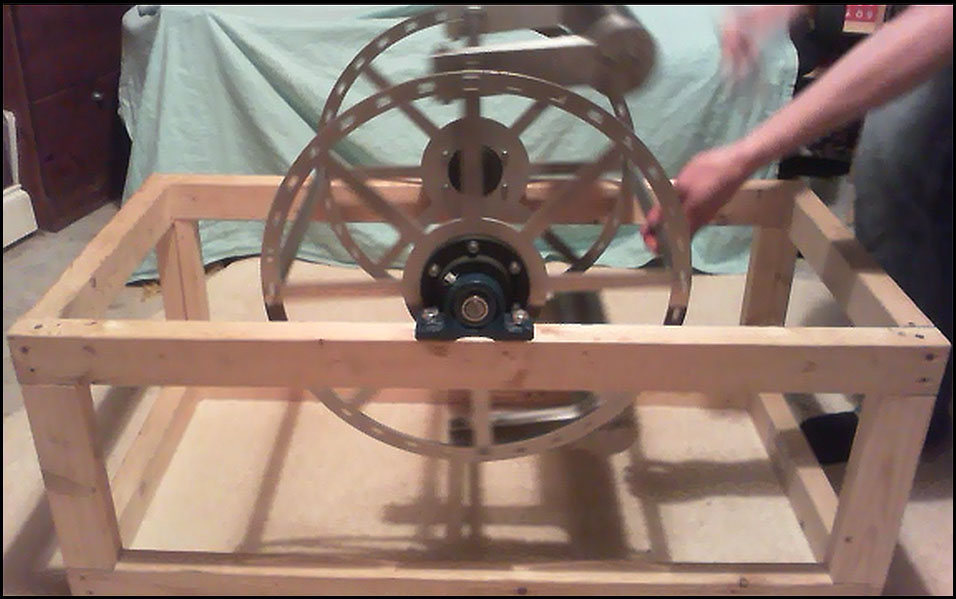
Yes, even though they are fitted, the device comes to a stop.
Originally posted by Mad Scientist
View Post
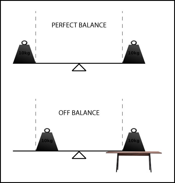
This is my point.
The center of mass is no longer in a position to overcome the friction.
Originally posted by Mad Scientist
View Post
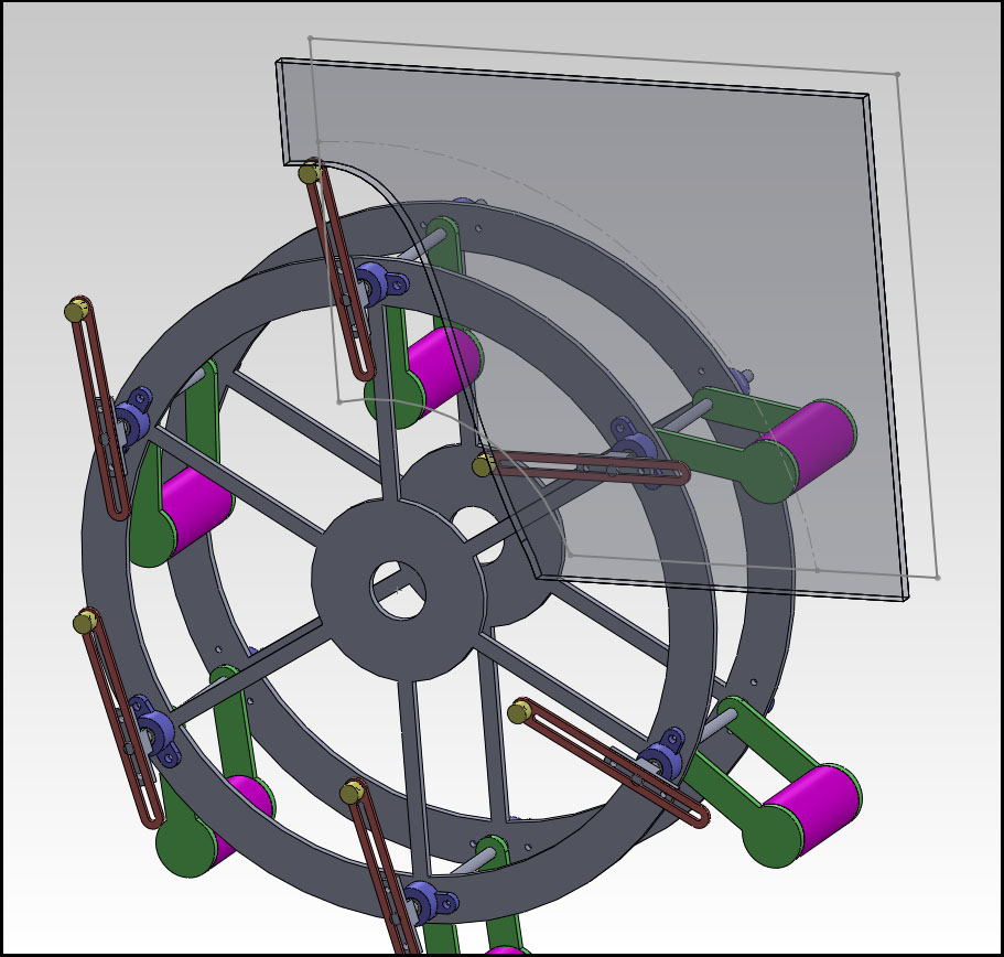
What do you see will happen based on the drawing so far?
You will have to use your imagination, that a frame, hub and main bearings are there.
Best regards,
Paul

 ) Thus I�ve looked at outright scams to those honestly trying to make something work.


Comment