Announcement

Collapse
No announcement yet.

Self-induction

Collapse
X
 
  • Filter
  • Time
  • Show
Clear All
new posts

  • The Its like I said, All the South coils create a spike that heads back to C1 and V1. They are negative on the scope and you can't see them because the probe is going to show you highest current first from V1.
    IE Look at the spikes coming out of monopole before and after the diode. You can't see them on the battery side.

    Either way I though I would point it out as something to look for. A little switching and you could keep all that power.
    Originally posted by erfinder View Post
    As stated the spike is always in the same direction. Everything in the device is setup to operate in one direction, this so that all forces can align, the ones we know about and the ones we don't.
    I'll leave ya alone. I don't want to thinkin the conversation up anymore.

    Matt

    Comment


    • Originally posted by Matthew Jones View Post
      The Its like I said, All the South coils create a spike that heads back to C1 and V1. They are negative on the scope and you can't see them because the probe is going to show you highest current first from V1.
      IE Look at the spikes coming out of monopole before and after the diode. You can't see them on the battery side.

      Either way I though I would point it out as something to look for. A little switching and you could keep all that power.


      I'll leave ya alone. I don't want to thinkin the conversation up anymore.

      Matt
      You can believe me when I say that I welcome input. Ask all the questions you like, and make all the suggestions you feel led to make. The charging of the buffer capacitor was not something that I planned. It was something that happened because the geometry was right. Looking for a way to keep the power supply from exploding resulted in me adding the buffer capacitor and diodes. I was looking for something else when this effect manifested. I have a better circuit, the ideal circuit. Its called a Mosfet commutator. That switch lets me capture everything, the positive and negative, with that switch I can switch 6x per revolution, switching on both halves of the wave, the reason why I don't use it its because that switch is bidirectional, and the effects I am after are unidirectional. At one point I thought that monopole meant unidirectional, I have come to understand (in my twisted way) that its not, we are dealing with two halves of a whole, and to get what I am after both poles are necessary.

      I dig how fast you respond....

      Not really sure if that made it any clearer. I don't care about the buffer charging in the general sense, I am interested in the path taken by that which is charging the buffer, its that path that I want to manipulate.


      Regards
      Last edited by erfinder; 01-19-2014, 03:19 PM.

      Comment


      • Originally posted by Duncan View Post
        look at the electrostatic force … where is its B force ? Where is the vector ? Its there all right its obvious as soon as you tune to series resonance …. Its missed out , just not there, tptb wanted that force for their own use, and still do! In due course when the truth will out .. as it always does. Why they'll just say … Its a miracle whoever would have guessed that was there. can't you smell and see the trickery?
        Hi Duncan

        I am way behind on threads at the moment and this Post 73 is as far as I am here.

        Yes TPTB want everything longitudinal for themselves, and you made me remember these words penned by 'The Father' of all electric (HV), magnetic, electromagnetically radiated and resonant technologies himself - Nikola Tesla - way back in 1919 -

        "The Hertz wave theory of wireless transmission may be kept up for some while, but I do not hesitate to say that in a short time it will be recognised as one of the most remarkable and inexplicable aberrations of the scientific mind which has ever been recorded in history."

        Am I so stupid that I find the hard-to-follow posts here in this thread as if a meaningless double-talk, for nothing of consequence has clicked so far ?

        Cheers ............ Graham.

        Comment


        • See Steve its been my experience in the systems that make those spikes for harvesting that the spike equals input power into that inductor. If you can catch it you never lost it. If you catch it and your input....?

          Thats a real nice little machine, my hats off to ya.

          Going to pull weeds in the garden now.

          Matt

          Comment


          • Originally posted by Matthew Jones View Post
            See Steve its been my experience in the systems that make those spikes for harvesting that the spike equals input power into that inductor. If you can catch it you never lost it. If you catch it and your input....?

            Thats a real nice little machine, my hats off to ya.

            Going to pull weeds in the garden now.

            Matt
            I understand what you're saying Matt, and even though what I'm saying might not make a whole lot of sense, or any sense right now, I will do everything I can to make sure that it does later. I welcome your input, and look forward to future posts from you.

            Thanks for the compliment on the machine.


            Regards

            Comment


            • Steve, I pm'd you.

              regards,
              Mario

              Comment


              • Originally posted by Mario View Post
                Steve, I pm'd you.

                regards,
                Mario
                Got it, check your box.

                Comment


                • I've been thinking about the whole think and I believe we all have a preconceived opinion which is easily shared without presenting the elements in a clear manner so we can see the strong and the weak points. From sharing a well presented point of view we all can achieve progress.

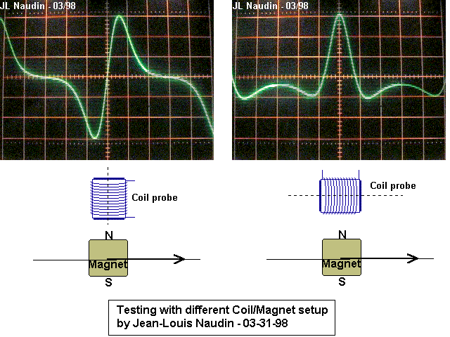
                  What we all have is a machine already built in a non-conventional manner and personally, I want to dissect it to understand it better. So I got a picture from Naudin site to help me in reasoning:


                  At this moment I am not interested in any kind of switching, I want to see what wave forms I can generate.

                  I have drawn 2 coils and I marked the "start" of winding with the dot (no more clock wise anti clock wise BS). Then I made the classic connections (series) of the two coils as in a dynamo and I got the picture attached (Double Coil 2.png). Note that both magnets are facing the North pole towards the coils (if the magnet in the right was facing the South pole, the wave would have been reversed).

                  One can notice and use this sequence in later experiments:
                  1. The magnet approaching the coil's winding from the left side, is giving an increase of emf in the coil.
                  2. Past that point, going to the center of coil, emf is decreasing
                  3. At TDC emf is zero
                  4. Past that point, going towards the other edge of coil, emf is changing polarity and is increasing
                  5. At right side of coil, in immediate vicinity of windings emf is max again (with different polarity)
                  6. Past that point, emf is decreasing

                  If I bring the coils closer together, I can have wave form joining together into a sine wave.

                  Lets assume that for a given speed of magnets, all facing N pole in front of 2 coils, the generated emf is 10V peak to peak.

                  We'll have exactly the same conditions (same given speed of magnets, all facing N pole in front of the same 2 coils) this time connecting the coils anti-series and bring them together (joined) as in Erfinder's machine.
                  As Leedskalnin did, I give you as second attachment the picture Double Joining Coil 2.png.

                  My question I asked myself and I invite you too to deliver an answer: is any advantage in using this connection as the generated emf wave is concerned?

                  Please feel free to use the second picture to help drawing the wave form and decide what is the peak to peak voltage generated.

                  After that we can use alternating magnetic poles.
                  Attached Files
                  Last edited by barbosi; 01-19-2014, 06:28 PM.

                  Comment


                  • Hi all,

                    I'm very glad to say that Steve has run the setup with an igbt as well and still got the back-charging effect . An igbt has no reverse diode so there is no (conventional) path for the coil to back-charge the supply cap.
                    This is very good news. I apologise if I have distracted from what he's trying to show to us, but I had to bring it up because with a Fet it could have been a possibility since on my setup the reverse diode allowed for the same results, back charging, but through the diode in my case.

                    So let's keep investigating this as I really think Steve has something very important that he wants us to see…

                    regards,
                    Mario

                    Comment


                    • Originally posted by Mario View Post
                      Hi all,

                      I'm very glad to say that Steve has run the setup with an igbt as well and still got the back-charging effect . An igbt has no reverse diode so there is no (conventional) path for the coil to back-charge the supply cap.
                      This is very good news. I apologise if I have distracted from what he's trying to show to us, but I had to bring it up because with a Fet it could have been a possibility since on my setup the reverse diode allowed for the same results, back charging, but through the diode in my case.

                      So let's keep investigating this as I really think Steve has something very important that he wants us to see…

                      regards,
                      Mario
                      How did I guess you were going to do that...LOL...I will shoot a new video tomorrow showing the IGBT run, the wave looks exactly like how you said it should Mario, with the exception of the thing that I wasn't ready to talk about yet...self oscillation.

                      Your posting about the reverse diode was a wonderful addition to the discussion, and was by no means distraction, I greatly appreciate you bringing it to the attention of all who are participating in our exchange of ideas.

                      Do keep pointing these kinds of things out! You humble me even more with this post! I am honored that you would share some of your precious time here with me.


                      Regards
                      Steve

                      Comment


                      • Originally posted by Mario View Post
                        Hi all,

                        I'm very glad to say that Steve has run the setup with an igbt as well and still got the back-charging effect . An igbt has no reverse diode so there is no (conventional) path for the coil to back-charge the supply cap.
                        This is very good news. I apologise if I have distracted from what he's trying to show to us, but I had to bring it up because with a Fet it could have been a possibility since on my setup the reverse diode allowed for the same results, back charging, but through the diode in my case.

                        So let's keep investigating this as I really think Steve has something very important that he wants us to see…

                        regards,
                        Mario
                        A "protection" diode was not required as long there is a load attached. EDIT: In fact can we test that by disconnecting the load?
                        How funny is that? you cannot charge if you don't consume...

                        But I have posted a chalenge as something necessary to see before jumping to analyze the switching. Anyone willing to take the work?

                        Last edited by barbosi; 01-19-2014, 07:39 PM.

                        Comment


                        • Originally posted by barbosi View Post
                          A "protection" diode was not required as long there is a load attached.
                          I know that. But that was not the point.

                          regards,
                          Mario

                          Comment


                          • Barbosi

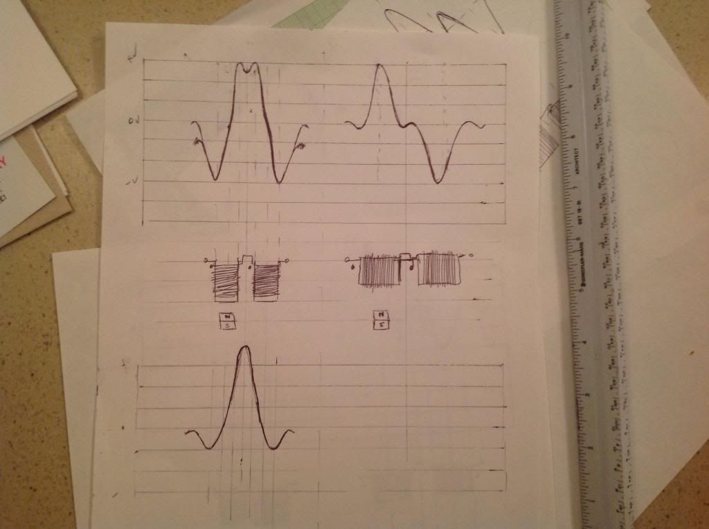
                            The two coils face on, in anti parallel has same wave form as a single coil side on, and viceversa. Using the junction tdc for Er's coils, is the same as using the zero crossing, for single coils on their side.
                            You may have a larger positive peak with Er's setup, as the negative peaks may be smaller, as I tried to draw in bottom waveform. Hope that was close to what you are trying to show. I wouldn't want to guess which is better, I wish I had my build finished.


                            Machine

                            Comment


                            • Excellent Machine,

                              Especially because you dared to consider also the other coil positioning. Without getting to discuss this, I hope you will find easy to apply the findings to that option too.

                              Now (discussing about top left drawing) because the coils are going to be even closer, touching each other (I dare to dream the windings could be even interlaced) is easy to see that the “pot hole” in the top would go flat. Also and the area around “0V” would lose its steepness a bit because the contribution of the other coil being in proximity.

                              Either way, one would conclude that the configuration has:
                              1. A higher content in harmonics => Question: Why?
                              2. About amplitude nothing has been said, let say we cannot know...
                              3. Counting the materials used, there is the same amount of wire for two coils. But how many magnets?

                              About using alternately two poles, there is nothing spectacular, the amplitude will go higher and will have the same shape above and below the zero line. While I admit I've been cheating a bit, I attach the picture with the answer I was thinking. Cheating is because instead of manually drawing it, I borrowed it from Erfinder's video and also I deleted the irrelevant (for now) pulse from switching.

                              Question repeated: why those harmonics?

                              Winner's prise: Muller Dynamo Experiments - YouTube pay attention to 1:35 minute mark. It was demonstreated also by Steorn before.

                              Excellent again Machine, when mind loose the shackles of book's dogma many wonders can present themselves. But work has to be done to maintain sharpness of the mind. Yours Sir, should be an example to many visiting here. And a friendly invitation for all to let go the shyness; here we will not face the consequences from a class room nor ridicule.

                              Regards.
                              Attached Files
                              Last edited by barbosi; 01-20-2014, 03:29 AM.

                              Comment


                              • Hi Barbosi

                                Ok, Ok... The "pothole" singular, at the wave peak, is fundamental and third, if there was two potholes it would be fundamental, 3rd, and 5th. If we add a few more we could start to make a very nice square wave..
                                The wave for a single coil, on it's side, is fundamental only.
                                Nice. But does it work better?, Tesla may still have a superior design, the Toroid was special, that I'm sure of, we'll see. LOL

                                Have either of you tried overlapping your coils, would you share that, if you have?

                                Barbosi, I'll watch that vid next.

                                Here is a cool vid I just found today.
                                The Harmonic Series. Machine Prototype. on Vimeo

                                Machine
                                Last edited by machinealive; 01-20-2014, 05:55 AM.

                                Comment

                                Working...
                                X