Announcement

Collapse
No announcement yet.

Energetics of Ferromagnetisem

Collapse
X
 
  • Filter
  • Time
  • Show
Clear All
new posts

  • Energetics of Ferromagnetisem

    This thread is about the "Magnet Pump" of Dr. Leon Dragone:

    Quote from Dr. Dragone's opening paragraph:


    "When a Permanent Magnet is placed inside a coil, and
    the current in the coil is turned on, the coil's field can
    aid or cancel the PM’s field. If the coil cancels the PM's
    field, the magnetic energy of this field is lost from the
    environment. Where does this energy go? To answer
    this question, let us describe the permanent magnet in
    terms of its circuital Amperian currents":


    http://192.211.49.220/-%20Free%20Ene...%20Dragone.pdf
    Last edited by Allen Burgess; 01-29-2014, 03:37 AM.

  • #2
    Interesting...

    Hello Allen Burguess,

    Nice Experiment there...some reactions are expected...

    1-If the Coil magnetic Polarity is oriented identical to PM...or looking at current passing coil as I (positive)...then it is understood that magnetic fields will sum, add magnetic strength...understanding if feeding to coil is linear or straight DC.

    2-If the Coil magnetic Polarity is opposite to PM...or current as -I (negative or reversed direction related to above example) ...then it is understood it is a matter of which is > than in order to judge who would be predominant in space magnetic polarization field.

    So, in order to "cancel" PM Field, then B Coil Field must be equal or greater than PM Field...

    If B Coil is under/lower in strength than PM, then PM residual after deduction from B Coil would be present.

    However, if we are "switching/pulsing" Coil with a DC...then the whole thing changes...just because, when you turn coil off...it will produce a reversed potential (+V where it was -V...and vice versa)...Plus the Radiant Field will come on on that momentum...which is opposite to the On Time, whatever it was...

    Therefore, if Coil pulsed was set at On Time as my description #1 above or on same magnetic polarity than PM..then at T-Off Radiant will tend to cancel PM Field...and depending on Coil set up...and other parameters could be bigger or lesser than PM Field.

    In the case #2 the opposite would take place...Radiant would favor PM Field at Off Times.

    To me, a very interesting side of this article is at the end...when he compares/applies previous tests to motors at attract versus repulse actions and consequences...


    Excellent !


    Thanks


    Ufopolitics
    Principles for the Development of a Complete Mind: Study the science of art. Study the art of science. Develop your senses- especially learn how to see. Realize that everything connects to everything else.― Leonardo da Vinci

    Comment


    • #3
      Adiabatic output.

      @Ufopolitics,

      Great analysis! I preformed a few experiments that I video taped, but I failed to measure a COP. A DPDT switch is required, so the output has a separate pathway from the input. Also, the "Magnet Pump" output pulse has to have a longer duration then the power pulse.

      The fascinating aspect of Dr. Dragone's experiments involve the relationship that follows after the coil pulse suppresses the PM field entirely. Dr. Dragone maintains that the removal of the magnet field takes power away from the PM that causes a drop in temperature in the magnet material. The magnet must restore the heat by absorbing it from the ambient background heat. This he calls the "Adiabatic effect". Looking closely at his equations, I interpret them to explain that there is a OU>1 COP, between what he calls the "Circuital Amperian Current" equal to the magnet's field strength in the restrictive coil pulse, and the power that's returned to the windings from the restructuring work done on the atomic domains. 20 times the power back!

      Quote from Dr. Dragone's "Energetics of Ferromagnetisem":

      "Again, and for the record the E-E motor has an efficiency of 20 to 1 in a no load situation. I think this motor should be looked at by the institute and this over unity effect can be verified first hand by you".
      Last edited by Allen Burgess; 01-29-2014, 07:49 PM.

      Comment


      • #4
        Magnet pump.

        Here's a low quality video of my first Dagone "Magnet Pump":

        Leon's Magnet Pump.mov - YouTube

        The important feature is the DPDT Reed switch, which opens a separate pathway to the capacitor for the output. The output comes exclusively from the resurgence of the magnet field that's displaced by the coil pulse.

        Comment


        • #5
          Originally posted by Allen Burgess View Post
          Here's a low quality video of my first Dagone "Magnet Pump":

          Leon's Magnet Pump.mov - YouTube

          The important feature is the DPDT Reed switch, which opens a separate pathway to the capacitor for the output. The output comes exclusively from the resurgence of the magnet field that's displaced by the coil pulse.

          cooling effect
          JLN Labs - The Newmans's Machine Cooling effect

          www.intalek.com/Papers/DragoneAnalysis.pdf

          The following paper by Leon Dragone was sent to me in 1989.
          Last edited by wings; 01-29-2014, 08:34 PM.

          Comment


          • #6
            Negative energy.

            @Wings,

            Thanks for those hyperlinks. The idea that restricting the field from a permanent magnet within a surrounding coil pulse, creates negative energy within the magnet is a challenge to understand. Sources raise the "Casimir effect" to try and explain what negative energy really is.

            This invokes the theory of ZPE:

            "Zero-point energy, also called quantum vacuum zero-point energy, is the lowest possible energy that a quantum mechanical physical system may have; it is the energy of its ground state".

            The practical side would involve the reappearance of energy in the "Magnet pump" power coil from the vacuum, that's measurable, and perhaps useful!
            Last edited by Allen Burgess; 01-30-2014, 05:37 PM.

            Comment


            • #7
              A sketch

              Allen, I am very interested to see how you have wired up your DPDT read switches as you were discussing in your video. Please can you post a schematic?

              Comment


              • #8
                DPDT switch.

                @MasterBlaster,

                I'm unable to do that right now, I'm sorry, but try and bear with me:

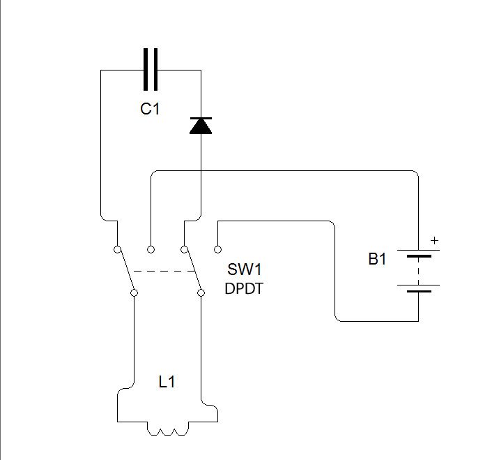
                The DPDT switch has six poles. The two poles in the center would wire to the two wires from each end of the coil. That leaves four poles; Two poles on each side of the switch: The pair of poles on one side would wire to the two electrodes of the storage capacitor, and the other pair of poles would wire to the two poles of the power source; In my case the positive and negative poles of the battery.

                The simplicity of this switch is beautiful. One way the power is delivered to the coil windings from the battery, and the other way the coil is connected to and outputting to the storage capacitor! The DPDT Reed switch goes one way on the positive pole and the other way on the negative.

                I used an industrial reed switch shorted directly to the battery and capacitor. The problem was that each pulse was of equal duration. A better way to approach this would be to attach an IC DPDT switch to a 555, bi-stable multivibrator, so that the power pulse has a reduced pulse width and the output pulse a lengthened duration.
                Last edited by Allen Burgess; 01-31-2014, 01:06 AM. Reason: change

                Comment


                • #9
                  Better Solution

                  @Allen, May be you should consider an H-bridge. L298 is pretty common.
                  Regards

                  MB

                  Comment


                  • #10
                    Hi

                    The DPDT 'relays' are a great bit of kit. Allen is this how you have it wired up?

                    I remember reading a few years back, that to nullify a magnetic field takes a quarter of the energy, compared with the 'energy potential' of the magnetic field - how true that statement is though I'm not sure.

                    Regards

                    John

                    Last edited by john_g; 02-01-2014, 07:59 AM. Reason: added diode to drawing

                    Comment


                    • #11
                      DPDT switch.

                      @john g,

                      Thank you very much for the schematic. That's the correct wiring. An alternative to the very complex H bridge circuit might be a DPDT Reed switch with an actuator disk consisting of a series of tiny negative magnets in a semi circle in adjacency to merely a few positive ones. This way the Reed switch would be held open for a longer duration on the output pulse. The problem with this lopsided disk is that it has to operate between ten and one hundred hertz, as Dr. Dragone estimates. At that speed it would tend to grow unstable.

                      Two other possibilities are first: A physical commutator, with brush electrodes and the second, an opti-cutter type commutator.

                      Dr. Dragone claimed his simple magnet pump produced a measurable COP of >40.

                      The idea that ZPE energy from the vacuum is cold, and the cause of the heat loss in the magnet opens the door to other complex energy exchange ratios!


                      Two other alternatives
                      Last edited by Allen Burgess; 01-31-2014, 06:09 PM.

                      Comment


                      • #12
                        Originally posted by Allen Burgess View Post
                        @john g,

                        Thank you very much for the schematic. That's the correct wiring. An alternative to the very complex H bridge circuit might be a DPDT Reed switch with an actuator disk consisting of a series of tiny negative magnets in a semi circle in adjacency to merely a few positive ones. This way the Reed switch would be held open for a longer duration on the output pulse. The problem with this lopsided disk is that it has to operate between ten and one hundred hertz, as Dr. Dragone estimates. At that speed it would tend to grow unstable.

                        Two other possibilities are first: A physical commutator, with brush electrodes and the second, an opti-cutter type commutator.

                        Dr. Dragone claimed his simple magnet pump produced a measurable COP of >40.

                        The idea that ZPE energy from the vacuum is cold, and the cause of the heat loss in the magnet opens the door to other complex energy exchange ratios!


                        Two other alternatives
                        @Allen

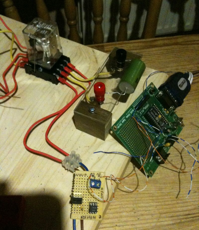
                        I have been using a DPDT relay driven by a STAMP PIC to operate the relay - see attached photo. So it is very easy to change the on/off times, although this may not be fast enough for you, with I think a 40ms cycle max rate for the relay - maybe there are very fast relays available?


                        Last edited by john_g; 01-31-2014, 09:09 PM.

                        Comment


                        • #13
                          DPDT switch frequency.

                          @john g,

                          Nice looking setup! Dr. Dragone states:

                          "The entire cycle would require from 10 to 100 milliseconds so that from 10 to 100 cycles can be made per second".

                          A 40ms cycle rate would be four times the minimum frequency, plenty to run the magnet pump. What are you up to with that circuit?

                          Looks like you could wire a magnet pump right into that circuit with no problem!

                          The schematic you supplied is correct with the exception of a fast switching diode that would connect in series with the capacitor in the actual one.
                          Last edited by Allen Burgess; 01-31-2014, 09:30 PM.

                          Comment


                          • #14
                            Originally posted by Allen Burgess View Post
                            @john g,

                            Nice looking setup! Dr. Dragone states:

                            "The entire cycle would require from 10 to 100 milliseconds so that from 10 to 100 cycles can be made per second".

                            A 40ms cycle rate would be four times the minimum frequency, plenty to run the magnet pump. What are you up to with that circuit?

                            Looks like you could wire a magnet pump right into that circuit with no problem!

                            The schematic you supplied is correct with the exception of a fast switching diode that would connect in series with the capacitor in the actual one.
                            @Allen thanks, I have added the diode to the above drawing. You asked "What are you up to with that circuit?" Strangely the opposite of your proposal - charging a cap to feed an inductor, the cap is swapped by the relay between the charge source and discharge circuit. I guess I will have to try the magnet pump now!

                            Regards
                            John

                            Comment


                            • #15
                              Originally posted by Ufopolitics View Post
                              Hello Allen Burguess,

                              Nice Experiment there...some reactions are expected...

                              1-If the Coil magnetic Polarity is oriented identical to PM...or looking at current passing coil as I (positive)...then it is understood that magnetic fields will sum, add magnetic strength...understanding if feeding to coil is linear or straight DC.

                              2-If the Coil magnetic Polarity is opposite to PM...or current as -I (negative or reversed direction related to above example) ...then it is understood it is a matter of which is > than in order to judge who would be predominant in space magnetic polarization field.

                              So, in order to "cancel" PM Field, then B Coil Field must be equal or greater than PM Field...

                              If B Coil is under/lower in strength than PM, then PM residual after deduction from B Coil would be present.

                              However, if we are "switching/pulsing" Coil with a DC...then the whole thing changes...just because, when you turn coil off...it will produce a reversed potential (+V where it was -V...and vice versa)...Plus the Radiant Field will come on on that momentum...which is opposite to the On Time, whatever it was...

                              Therefore, if Coil pulsed was set at On Time as my description #1 above or on same magnetic polarity than PM..then at T-Off Radiant will tend to cancel PM Field...and depending on Coil set up...and other parameters could be bigger or lesser than PM Field.

                              In the case #2 the opposite would take place...Radiant would favor PM Field at Off Times.

                              To me, a very interesting side of this article is at the end...when he compares/applies previous tests to motors at attract versus repulse actions and consequences...


                              Excellent !


                              Thanks


                              Ufopolitics
                              Hi UFOpolitics

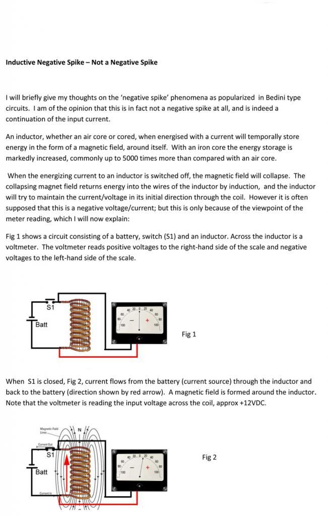
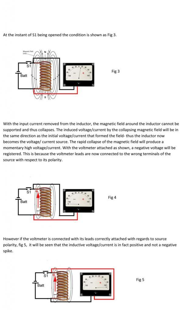
                              Hoping to not upset the applecart - but 'we' keep referring to the inductive collapse as a negative / reversed potential, whereas I think - (very much open to correction) that it is just the way the meter is attached to the load that it appears reversed, although the current continues in the same direction. I have had some people (not on this forum) get very angry about this explanation - I would appreciate your comments.

                              Regards

                              John


                              Comment

                              Working...
                              X