Announcement

Collapse
No announcement yet.

Energetics of Ferromagnetisem

Collapse
X
 
  • Filter
  • Time
  • Show
Clear All
new posts

  • #16
    Simple proof

    Hi John,

    There are several people on this forum that will not agree with the explanation you have posted. However that does not make them right.

    A simple circuit that proves that explanation is correct is the the Bedini SSG. If you look at how the charge battery and diode are connected it is clear that the only way the charge battery could charge is if the explanation you shared is correct. If the current reversed as some believe then the diode would be reverse biased and the charge battery could not get charged. Thanks for sharing a very clear and correct explanation of how a coil discharges.

    Respectfully, Carroll
    Just because someone disagrees with you does NOT make them your enemy. We can disagree without attacking someone.

    Comment


    • #17
      Originally posted by Allen Burgess View Post
      "The entire cycle would require from 10 to 100 milliseconds so that from 10 to 100 cycles can be made per second".

      A 40ms cycle rate would be four times the minimum frequency, plenty to run the magnet pump. What are you up to with that circuit?
      You could maximize the output by knowing the the time to fill inductor. Shut the system off and switch just before saturation. Maybe 90%. The last 10% costs the most in transmission and heat loss.

      There would be no need to stay on any longer. The transient has value as well and will appear and discharge in a given time. That math is more illusive.

      Then the relay may not have the ability to keep up unless you size your coil based on the math. A small inductor will Charge/discharge faster than something that is very large. But you can go to an H bridge setup with high voltage Fets and that will allow for a smaller inductor and higher rate of switching. But then you have to pay for the switching. Transistors may do the job with few tricks on the base to shut it off faster than the other set turn on. But minimal switching cost for sure.

      Anybody want to try let me know I'll draw it for you if you need it.

      Matt

      Comment


      • #18
        Experimenting

        Hi folks, I was testing with a magnet inside a coil, but it either threw the magnet away or made just a vibration, although I only had a bar magnet and a coil from a MOT.
        From what I read it shows a cylindrical magnet surrounded by a coil. Maybe that's the difference?
        John, I like that explanation, when inducing a coil with an alternating magnetic field , instead of a power source, the coil must reach a maximum, when seeing the north pole , then drop , then rise again but opposite ,since the south pole is approaching???
        And as the north leaves, does the coil ,create a south ,due to collapse , thus repelling the oncoming south magnet?
        If you short the coil at the right time ,during the alternating magnetic induction, you can store more power in caps, than under normal operation.
        If somebody could make a circuit where you could control the speed and the timing of the shorting, I think an OU device wouldn't be far behind.
        I've been trying mechanically but , as rpm increase they can't keep up.
        artv

        Comment


        • #19
          Magnets and coils

          Hi shylo,

          I have done quite a bit of work with coils and magnets passing so I will try to answer your questions about the action of the magnet on the coil. In our first example let's look at a configuration of a single magnet and a single coil. For this first test let the magnet be mounted so that a single pole is facing out as in the SSG. When the magnet approaches the coil it will induce a voltage and the polarity will depend on how the coil is wound and on whether the north or the south pole is approaching the coil. For the sake of this discussion let's say the magnet induces a positive voltage. Now at the point where the magnet is centered (neither approaching or leaving) the voltage will drop to zero. As the magnet leaves the coil an opposite polarity or in this case a negative voltage will be generated. The reversing polarity is caused by the magnet leaving instead of approaching the coil. It doesn't have anything to do with the approach of the next magnet.

          If you want to see some of these effects you can make a simple setup to see them. Find an old cd player and take out the motor and leave the hub on for turning the cd. Then mount an old cd onto the hub using super glue or epoxy. Then you can mount some magnets onto the edge of the cd. Find or make a coil and connect 2 leds to the leads of the coil so that one led is turned to the opposite polarity of the other. Connect them in parallel. Now if you give the cd a spin you should see both leds light up.

          If you want to see something more interesting get a magnet that has one of the flat sides as north and the opposite as south. The magnets you can get at Lowes are like that. Mount it on the edge so that the end of the magnet passes the coil. In other words you want the magnet to go by so that first one pole and then the other of the same end of the magnet will pass by the coil. What you will see is only one of the leds will light. If you spin the magnet past the coil in the other direction you will see the other led light up.

          The reason for only one led lighting is because of the following: When the magnet is approaching the coil one pole is approaching but when leaving the coil the opposite pole is the one leaving and therefore it induces a voltage the same as the other pole did when it was approaching.

          I hope these ideas will help you understand the relationship between coils and magnets.

          Respectfully, Carroll
          Just because someone disagrees with you does NOT make them your enemy. We can disagree without attacking someone.

          Comment


          • #20
            Not to detract from the thread but after looking @ magnacoaster patent, I believe this principle is where his excess is coming from.

            Comment


            • #21
              Not again!!...!!!

              Originally posted by john_g View Post
              Hi UFOpolitics

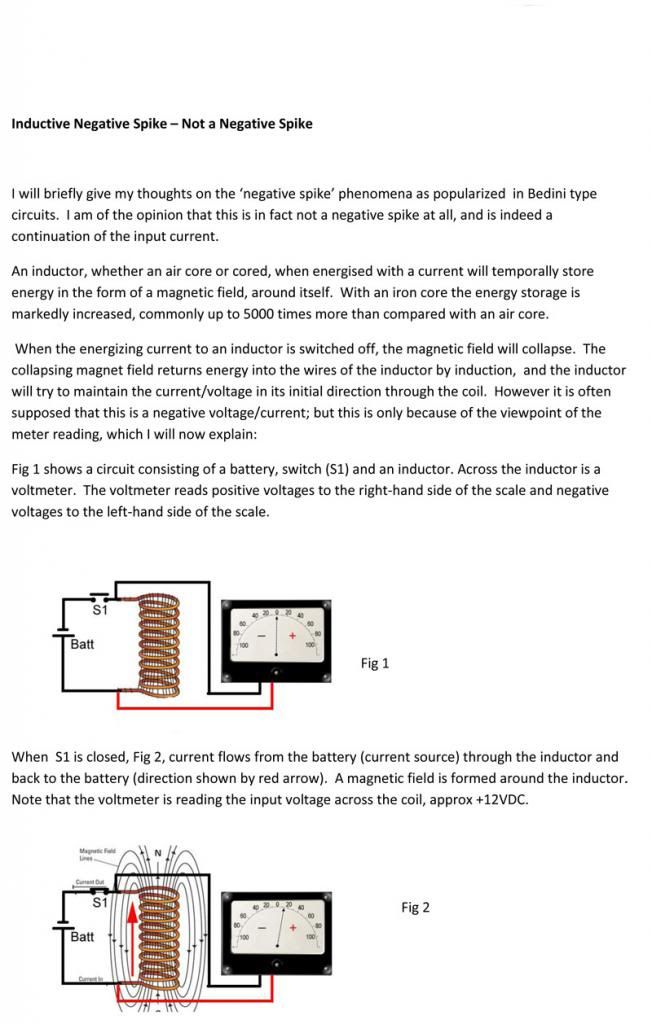
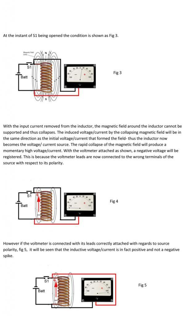
              Hoping to not upset the applecart - but 'we' keep referring to the inductive collapse as a negative / reversed potential, whereas I think - (very much open to correction) that it is just the way the meter is attached to the load that it appears reversed, although the current continues in the same direction. I have had some people (not on this forum) get very angry about this explanation - I would appreciate your comments.

              Regards

              John


              Hello John,


              John, I have no idea who wrote and made those diagrams...I spent almost a year, before I disclose my Second Thread (Machines)...just arguing about this in my First Thread on this Forum...testing and going over this issue to exhaustion...and now John...honestly, I am not going to start a long and deep argument again.

              ...I will just "drop here" an existing Methodology to design DC/DC Converters...and a specific one which I like..just because it uses Two Inductors to Output Power...The SEPIC, I will leave the link to Wikipedia...I have studied this DC/DC Converters or "Buck/Boost Family" to exhaustion, and I have read many books and articles and different Engineering Papers and Discussions about much more extensive explanations...

              S1 Closed:

              [IMG][/IMG]

              S1 Open:

              [IMG][/IMG]

              Just note a simple detail...watch D1 (Diode 1) at opening of S1 (Time Off), A FET , Same thing as the "physical" switch that author of article shows...If L1 wouldn't have, ok, let's put it this way, not to create more arguments, I won't say "reverse" but "SWING" to Positive Voltage on the side of D1, never, transmission of electric flow will occur to output from L1 Negative DRAIN of FET side...

              Now, I do know that L1 (Current) remains in same direction, as could be observed in red arrow "VL1"..."However", coil "swings" positive on the IL1 leg....We all know that Inductor "tends" to keep current constant...and in order to achieve this "miracle"...it swings or reverses voltage...

              You could also look up the simplest of the "Family"...and respond how it would be possible that Diode could allow forward bias (Negative it is) to Output (at Off Stage, of course) of this very well known device, if Inductor will not reverse polarity...or, am sorry, meant to say..."swing" polarity (seems like a more "appropriate terminology"... )?!

              [IMG][/IMG]

              File:Buck-Boost Converter.jpg - Wikipedia, the free encyclopedia

              Understanding in this case S1 is a P-Chanel FET...and the Output is REVERSE from Input...I have one of those as well and they work wonderful..
              This Devices utilizes very fast switching of FET's...in order to get their results and higher efficiency... Inductor's job is to discharge to Output Cap at off stage, and charge at on stage.


              Regards John_G


              Ufopolitics

              On a Separate note: The explanation I rendered above, about swinging voltage is NOT correct either, or better said..."there is MUCH more to this"...I just wanted to demonstrate through an existing device that anyone could buy on EBAY...that it DOES reverse V Polarity......But , there is more to this phenomena as we could analyze in simple/plain "viewing/analysis"...but I really do not want to distract/deviate this Thread...watch my videos on Radiant, go over my First Thread here...where I have spent hundreds and hundreds of hours making ,testing and posting results...

              ASYMMETRY TO ENLIGHTENMENT - YouTube

              DEFINING RADIANT ENERGY FIELD (Part 1) - YouTube

              Have a nice evening
              Last edited by Ufopolitics; 02-03-2014, 05:09 AM.
              Principles for the Development of a Complete Mind: Study the science of art. Study the art of science. Develop your senses- especially learn how to see. Realize that everything connects to everything else.― Leonardo da Vinci

              Comment


              • #22
                Originally posted by Ufopolitics View Post
                ...but I really do not want to distract/deviate this Thread...watch my videos on Radiant, go over my First Thread here...where I have spent hundreds and hundreds of hours making ,testing and posting results...
                LOL I think you are incapable of NOT pushing that garbage of your's LOL. So full of yourself, you must somehow include your copied junk in every conversation you have. LOL

                So Sad this is what this forum is reduced too, the stomping of self centered plagiarists.... so sad.

                Matt

                Comment

                Working...
                X