Announcement

Collapse
No announcement yet.

Steele Braden Generator

Collapse
X
 
  • Filter
  • Time
  • Show
Clear All
new posts

  • #31
    Thought i drop that Video here how a Guy build a Wimhurst. Looks easier at all as to buy plastic Disks.
    Wimshurst Machine Build Part 1 - YouTube


    Found another even more simply one with Cd-Disks
    How To Build a CD Wimshurst Machine - YouTube
    Last edited by Joit; 02-19-2014, 09:14 PM. Reason: add link
    Theorizer are like High Voltage. A lot hot Air with no Power behind but they are the dead of applied Work and Ideas.

    Comment


    • #32
      Hey I found this while searching for my own pics on photobucket:
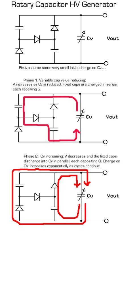
      Rotary Capacitor HV Genereator
      Developed by Dr. Cyril Curtis circa 1970.

      [IMG][/IMG]

      I thought it was related enough to share.
      Last edited by kenssurplus; 02-18-2014, 07:04 PM.

      Comment


      • #33
        From Steele

        Kenssurplus
        Yes, this is certainly a viable alternative.
        The difference between Dr. Cyril Curtis machine and mine is basically the diodes and extra caps in his, whereas with mine, the only caps are the “working” (rotating) caps, and as such is a somewhat simpler machine system
        My machine is for producing AC output.
        “Advances are made by answering questions. Discoveries are made by questioning answers.”
        —Bernhard Haisch, Astrophysicist

        Comment


        • #34
          Hi Dave

          I have a question for Steele that has been bugging me for a while:

          When I first built my version of the rotary capacitor, I originally used 4 quarter sections as "petals" on both the rotor and stator, but looking at the way the capacitance operates on both opposing stators at the same time, I concluded that they would be fighting each other for part of the rotation and would not achieve the highest voltage swing unless there were a blank spot where niether stator would have any rotor petals meshed. Did you look into anything of this nature? Would the extra voltage swing of a complete blank spot be outweighed by the loss of plate area?

          That is why my version has eighths sections in stead of quarters. I will see if I can draw a diagram and show what I am talking about.

          Comment


          • #35
            My thoughts

            I am sure Steele will email me soon with his response, but I can tell you from what he has explained to me that you need to have the petals on one rotor coming out of alignment at the same time as the petals on the other rotor are coming into alignment, or else the generator is NOT as efficient. The petals need to have no square corners. All surfaces need to be as rounded as possible. You do NOT want those blank spots or it is less efficient.

            If Steele has more to say on the subject I will post it as soon as he checks in.

            Dave
            “Advances are made by answering questions. Discoveries are made by questioning answers.”
            —Bernhard Haisch, Astrophysicist

            Comment


            • #36
              US Patent No. 4,897,592

              Have a look at the referenced Hyde patent "Electrostatic Energy Field Power Generating System" for some ideas on rectifying the HV output.

              Comment


              • #37
                Kenssurplus
                Re “blank” spot of no aluminium foil petal.
                One of many experiments I did, involved using just one “half moon” foil petal on rotors and stators.
                Yes you do get greater capacitance swing, but the “down” side is that you need 3,000 RPM for just 50 HZ output.
                I considered this unduly high for the diameter rotors I wished to use.
                So there is a “trade-off” here.
                More petals = lower RPM usable but with less capacitance swing.
                At present, with 6 petals, the capacitance when fully meshed, turns out to be exactly halved when fully unmeshed.
                For the swing of every 440 picofarads, at 20kv, 20 watts flows.
                One may think that many thin width petals would be best, as then you could have much higher frequency output at low RPM.
                However, the separation distance between the petals EDGES is also important.
                If these are too close, the capacitance swing also drops off.
                So 6 petals seems to be the optimum.
                Hope this helps.
                “Advances are made by answering questions. Discoveries are made by questioning answers.”
                —Bernhard Haisch, Astrophysicist

                Comment


                • #38
                  been away

                  Been away for a week but hope to get back on this now.

                  The down side of 3000 RPM is not applicable to a 4 pole (petal) unit as that only needs to rotate at 1800 for 60 hz and 1500 for 50 hz or 1200 / 1000 for a 6 pole unit.

                  The issue of having a blank spot does not affect the RPM any but does affect the overall surface area of the petals and non petals or holes(if that makes any sense) and so would affect the total capacitance. Is this the separation distance you were referring to or is that the separation of each individual petal's edge to edge?

                  I am thinking of using an 14 inch diameter aluminum magnetic tape reel which already has 3 hols cut out (need three more to make a six pole unit).
                  See:[IMG]photobucket.com[/IMG]
                  If anyone can help out with ideas of mechanical mounting to shaft / housing etc. I am very open for suggestions.
                  Last edited by kenssurplus; 03-01-2014, 08:23 PM.

                  Comment


                  • #39
                    From Steele

                    Regarding using the three”windows” rotor.
                    Whilst this at first looks great to use, as it is an already perfectly engineered “off the shelf” rotor, there are unfortunately several factors that render it unsuitable.
                    Open windows in the rotor will cause considerable air drag friction.
                    The ratio between no metal (windows) and metal, is uneven.
                    This would produce a rather strange output.e.g. sinewave, no sinewave, sinewave, no sinewave, etc.
                    What we need is a continuous unbroken sinewave output.
                    This can only be achieved with equal ratio metal/no metal arrangement, 50% metal and 50% no metal.
                    Also with the windows method, this would be further inefficient because of the unused (wasted) area from the window to the periphery of the rotor.
                    Also the unused area from the window to the hub of the rotor.
                    You need to take full advantage of as much change in capacitance swing as possible.
                    My original design achieves this.
                    Afixing rotors to shaft.
                    I made up solid metal “top hat” shaped hubs with set-screws to screw down onto the shaft.
                    Two small bolts with nuts through the top hat flange go through the rotors.
                    This holds everything square on the shaft and rigid.
                    This method also makes the electrical connection required from the rotors metal parts to the shaft.
                    An alternative to my aluminium foil on plexiglass rotors, is to use double sided printed circuit board.


                    If you change Steele's design you will not get Steele's results. Yours may be better or worse. But in my experience it is always better to replicate as closely as possible first so that you see what a design is capable of, and THEN try to improve it. I built a two rotor model and it did exactly what he said it would do. Now I have moved on to a larger version. I was going to do four rotors, but have decided to go ahead and shoot for eight. It will take me a little while as I am busy with several things, but I will get there.
                    “Advances are made by answering questions. Discoveries are made by questioning answers.”
                    —Bernhard Haisch, Astrophysicist

                    Comment


                    • #40
                      Hi Dave,

                      It seems as though I have presented the wrong impression. I am not trying
                      to be a 'my way or the highway' prideful a$$. I completely understand about not changing the working proven design when replicating. The trouble is, I would do it exactly as Steele has shown if I could, but presently I have no budget to purchase anything, and it looks like that will likely be the case for quite a while. So I have to use what I have on hand if I want to do any experiments or build anything.

                      That said, I am trying to operate as close to the design specs as I can using what I have. These are some of the items I am considering using:

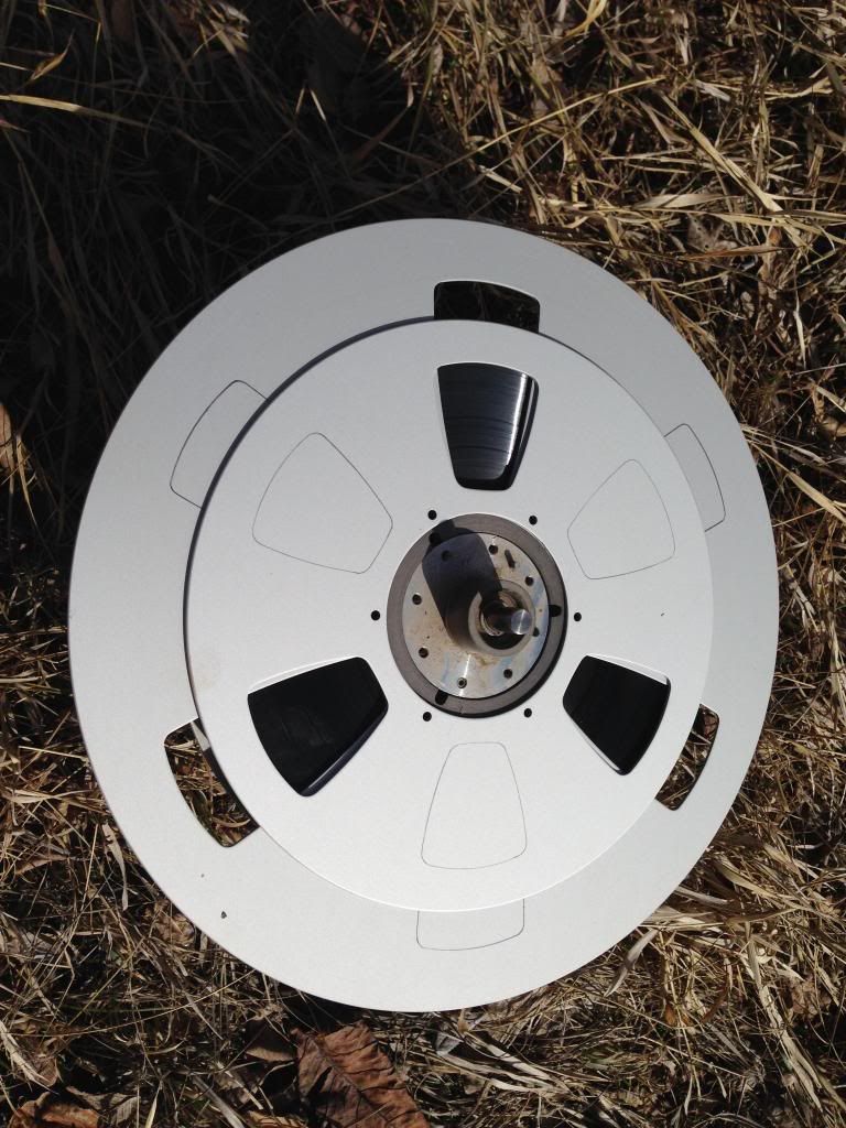
                      [IMG][/IMG]

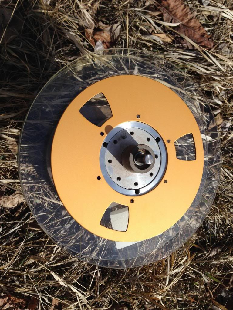
                      [IMG][/IMG]

                      The large aluminum reel is 14 inches diameter with a 3 inch ID removable hub. Most all of the reels I have are built this way.
                      The smaller aluminum reel is 10.5 inches diameter and the gold reel is 8 inches.
                      I only have 2 14 inchers (4 identical sides) which I was considering using as stators.
                      I have probably 50 or so of the 10.5 inch reels and about the same of the 8 inch reels.
                      I also have about 100 of the glass reels but I have not figured out how to remove the glass sides from the aluminum hubs as they are glued on with some pretty tough glue.

                      If I use a combination of these reels, I have to figure out how to adequately insulate all the components, and I have very little amounts of acrylic sheet.

                      I am sorry if this seems too much of a deviation from what Steele has shown and described. If It is, then I can bow out and not clutter the thread with my messes.

                      Ken
                      Last edited by kenssurplus; 03-10-2014, 06:03 PM.

                      Comment


                      • #41
                        From Steele

                        kenssurplus

                        Hi Ken.
                        I think I understand what you intend to do.
                        Put an additional three windows in the rotors.
                        I think that the windows widths will still not make up an even amount of no metal to metal ratio as the windows appear slightly too narrow.
                        This will still give a non-continuous sinewave output.
                        Also you still have the wasted (unused) portions of metal between the windows and the periphery of the rotor – likewise between the window and the hub.
                        The windows, unless filled in with a non conducting material, will as stated previously, cause considerable air drag friction.


                        Ken,
                        Since you seem to be the only one even TRYING to replicate this, I wouldn't worry about cluttering the site with your mess! LOL. At least there is SOMETHING to clutter the site with!!!
                        Here is a video I took today of my progress on my bigger setup.
                        \Steel's Gen - YouTube
                        I took it apart and started over right before I made this video, but I am finally making some progress. I spent most of the afternoon today cutting out aluminum petals, but I have about 40 more to cut before I am done. No rest for the wicked I am afraid. I feel bad that I haven't got a finished product to show you folks, but I am getting there. I just have TOO many projects all going on at the same time. For an out of work old guy I keep awful busy!

                        Dave
                        “Advances are made by answering questions. Discoveries are made by questioning answers.”
                        —Bernhard Haisch, Astrophysicist

                        Comment


                        • #42
                          Update

                          Steele's Generator 2 - YouTube

                          Here are all the "petals" cut out to go on the rotors. I now have two completed rotors and enough petals to do ten more. I have a total of 12 rotors, but I'm not sure all of them will fit. I haven't measured it yet. It's as long as I could make it and still get a piece of threaded rod to use to align the bearing holders. Won't get much more done until sometime tomorrow evening, but hope to get all my rotors done this weekend as well as the stators. That probably won't happen, but I will keep posting the progress.

                          Dave
                          “Advances are made by answering questions. Discoveries are made by questioning answers.”
                          —Bernhard Haisch, Astrophysicist

                          Comment


                          • #43
                            @Turion

                            Hi Turion,
                            I certainly am following the progress in your project, although I do not have time and equipment at the moment to attempt a replication of this interesting Steel generator.
                            If a little funds can help you in finishing this project, I surely would like to help.
                            So if you are positive, I can send you some bucks through Paypal.

                            aaron5120

                            Comment


                            • #44
                              aaron5120,
                              I appreciate the offer! But it's really not necessary. I already have all the materials required to put this together. All I am lacking is a large block of time to get it done. I am actually going down in the basement in just a few minutes to put in a few hours on it. I should be done sometime this week. But I can tell you this. I wouldn't have built this second, much larger build if I hadn't seen extremely interesting results on the smaller one I set up.

                              We are in the process of selling a house and moving, so I have repairs to make on the house we are trying to sell, repairs to make on the house we are moving into, a vehicle to rewire that we need to use to pul our trailer to haul stuff to the new house, my motor generator/project I have spent over a year on and a few thousand dollars to develop, my 3BGS research which is always ongoing, another project replication with a small group of guys, and my build of Steele's generator. I just don't have as many hours in the day as I have things to do. It is a good thing I am semi-retired and only have to work when I want some extra money or I would REALLY be in trouble.

                              But I will get there.

                              Dave
                              “Advances are made by answering questions. Discoveries are made by questioning answers.”
                              —Bernhard Haisch, Astrophysicist

                              Comment


                              • #45
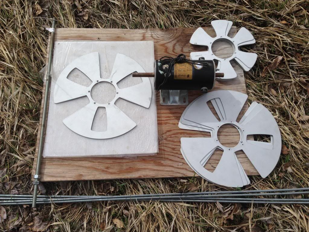
                                plate and petal progress

                                Hi Dave, Aaron5120, Steele, and All,

                                This is my progress so far. Almost ready to put all the pieces together. I still am a little stumped as to how to best mount the rotors to the 1/2 inch allthread.
                                I planned on hot glueing the stators to the acrylic sheet, that way I can peel off the glue and redo it If I don't like it.

                                Each stator takes 2 sheets of acrylic (one on each side) but I only have 4 sheets of acrylic. I need another large sheet of acrylic(30 in. X 60 in.) to insulate the other remaining stators from the rotors. I guess for now I can just test with 2 stators and 4 rotors.

                                [IMG][/IMG]

                                Comment

                                Working...
                                X