Announcement

Collapse
No announcement yet.

Cap Dump Circuit

Collapse
X
 
  • Filter
  • Time
  • Show
Clear All
new posts

  • My main purpose for making these gifs is to show the polarity reversal of the collapsing magnetic field.

    Pos pulse neg return - neg bemf

    Neg pulse pos return - pos bemf

    This indicates ionization to a certain degree is taking place.

    BIG CLUE
    Half of the Answer is knowing the right Question

    Comment


    • I would advise to copy and save this one.
      The open ended bifilar winding ionizes the field on the pulse and collects bemf on the collapse.
      Allowing the coil to draw from the ambient.
      Thank You Mr. Tito on OU forum.


      Edit: I believe he twisted the bifilar windings, Like Bedini showed.
      Last edited by Dave45; 07-26-2014, 01:33 PM.
      Half of the Answer is knowing the right Question

      Comment


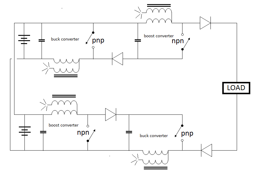
      • The next logical step, capacitive discharge on both sides.
        Last edited by Dave45; 07-26-2014, 06:51 PM.
        Half of the Answer is knowing the right Question

        Comment


        • Backup

          What are you doing, trying to find free energy?
          Last edited by Dave45; 07-26-2014, 07:46 PM.
          Half of the Answer is knowing the right Question

          Comment


          • Great Circuits

            Totally Outrageous

            This is what I was talking about before Dave, you are way out there and I got to try these on my new experimenters board I am setting up this week.

            I understand that the length of wire is sort of up for grabs here but if you got some results you liked or if others you know used a certain size, let us know.

            I am going to assume that Bifilar means like John Bedini twist's his wire up.

            Super exciting circuits. I am out of air just looking at them all.


            Another note: Is this four separate coils or 2 coils or one coil on one core?


            Mike
            Last edited by BroMikey; 07-26-2014, 10:05 PM.

            Comment


            • Four separate coils Mike

              Matt gave instructions for the coils
              Half of the Answer is knowing the right Question

              Comment


              • Coils?

                Originally posted by Dave45 View Post
                Four separate coils Mike

                Matt gave instructions for the coils
                Thanks for the heads up I guess that solves that problem real fast.

                I will wind my own coils and anything else I need I will just ask whoever is working on this stuff. I have seen this so many times. The guys that come up with these designed don't want to do them anymore and it just sits there.

                There are basket coils and star coils, toroidal coils, Tesla coils, loose coupling, tight coupling, iron wire coils, silver coated Teflon magwire coils, stranded wire wound coils, chock coils the size of my thumbnail, coils as big as a wheelbarrow.

                Coil cores of iron epoxy, air, magnesium, nickel, chromium, and the list goes on out into Never Never-land.

                I think coils of almost any kind will work some but the core such as John Bedini has pointed out is best for radiant captures. Also coils can be put in close proximity to one another when there are four of them like this operating off the same circuit.

                SO I think the placement of the 4 coils could create a further interaction as each one might collect something from the other as the circuit runs.

                YOU GOT ME THINKIN DAVE http://www.energeticforum.com/john-b...verter-19.html

                Mike
                Last edited by BroMikey; 07-27-2014, 12:04 AM.

                Comment


                • I cant access the ssg thread, this is more of a cap dump circuit anyway.
                  Im not sure if this can be scaled or not but if it could.
                  Half of the Answer is knowing the right Question

                  Comment


                  • The power would increase for each stage so the components power handling capability's would change.
                    Fine wire on the boost and heavy on the buck, that would change in each stage as well.

                    Folks the buck boost tech has been around for a long time, I just started adding it together in stages.
                    Half of the Answer is knowing the right Question

                    Comment


                    • Last edited by Dave45; 08-02-2014, 11:52 AM.
                      Half of the Answer is knowing the right Question

                      Comment


                      • Folks this is an overcomplicated boost converter that puts out 320 volts, instead of taking the power out you run it into a cap and add another stage.
                        Each stage increases power.
                        Last edited by Dave45; 08-02-2014, 12:22 PM.
                        Half of the Answer is knowing the right Question

                        Comment


                        • Lets say I wanted to build a buck converter, I could hook it to a 12 volt battery and hit it with 12 volts or I could hook it to this circuit and hit it with 320 volts.
                          Do you see it now.
                          A boost converter increases voltage a buck converter increases amperage.
                          You have to be careful how its laid out because you can get inverted voltage and inverted amperage.
                          Last edited by Dave45; 08-02-2014, 12:55 PM.
                          Half of the Answer is knowing the right Question

                          Comment


                          • Inverted power

                            Originally posted by Dave45 View Post
                            Lets say I wanted to build a buck converter, I could hook it to a 12 volt battery and hit it with 12 volts or I could hook it to this circuit and hit it with 320 volts.
                            Do you see it now.
                            A boost converter increases voltage a buck converter increases amperage.
                            You have to be careful how its laid out because you can get inverted voltage and inverted amperage.

                            Hi Dave just got in

                            You say each stage increases power handling? One behind the other and matching stages to keep losses down because every time we put power through a switch, coil or resistor we get a power reduction from what power was first introduced.

                            For instance the Microwave oven inverter boards. The object was to build a circuit to do away with the loss associated with block transformers.

                            Engineering rules had stated in the past that a transformer would only pass about 70 percent and 30 percent was lost in the isolation or conversion as you prefer.

                            When modern science introduced the inverter technology energy efficiencies of circuits jumped from 70 percent to 99 percent, however these conversions have been made using power transformer toroidal cores with the same efficiencies.

                            So as a rule we will say that modern engineering practices only capable of designing circuit with energy coefficients of less than 99 percent.

                            Inverter tech has been around a mighty long time but did not gain momentum til the 1990's when Harrison and Motorola got old and grey selling out to companies like "ON SEMI" when the new kids on the block took over.

                            Most of the people on these forums were still infants at that time however the historical data is present in the record.

                            Back to the Microwave ovens. Inverter boards to handle 5000 volts sent to a magnetron are not inexpensive to build, hence the block transform still prevails today with common microwave ovens. The see 10 microwave ovens a month for both commercial use and residential.

                            The issue here is efficiency VS durability on the microwave ovens.

                            So while all of these inverter technologies exist it appears making them practical for long term use is questionable. Longevity is may main concern building equipment.

                            Applying these topologies to our coils in a completely different animal

                            Mike

                            Comment


                            • Smaller Circuits

                              Originally posted by Dave45 View Post
                              The power would increase for each stage so the components power handling capability's would change.
                              Fine wire on the boost and heavy on the buck, that would change in each stage as well.

                              Folks the buck boost tech has been around for a long time, I just started adding it together in stages.

                              Hi Dave

                              I am no expert on this subject but let me share my thoughts with you so you can understand my statements about durability.

                              Each switch degrades the amount of power being processed in tiny amounts so the more buck-boost-boost-buck stages add to more and more losses.

                              The only reason I can see to use a cascading array is to fine tune or taylor make circuits to place into miniature devices.

                              I am at a loss to understand the reasoning behind adding so many stages and what the potential benefits might be.

                              99 percent power handling is a great start I agree. After we do our very best with the switching our coils won't have to work so hard to bring about a COP greater than 1? Is this the idea?

                              Mike

                              Comment


                              • Originally posted by Dave45 View Post
                                Lets say I wanted to build a buck converter, I could hook it to a 12 volt battery and hit it with 12 volts or I could hook it to this circuit and hit it with 320 volts.
                                Do you see it now.
                                A boost converter increases voltage a buck converter increases amperage.
                                You have to be careful how its laid out because you can get inverted voltage and inverted amperage.

                                Tito Images


                                Mike

                                Comment

                                Working...
                                X